Week 10
Hi!
This week we explored how electronic systems produce physical actions, such as movement, light, or sound, through different output devices. Understanding how to control these devices efficiently is crucial for interactive systems, robotics, and automation projects.
Power Management
Powering output devices requires careful consideration of voltage (V) and current (A). Let's review some concepts.
-
Voltage (V): Determines the potential energy available to drive the device. Higher voltage can increase power but must be within the device’s tolerance.
-
Current (A): Represents the flow of electricity. Motors and actuators typically require high current, which must be managed to avoid overheating or damaging components.
-
Power (W): Given by the formula P = V × I, understanding this helps in choosing power supplies and components.
-
Voltage Regulators: Used to ensure consistent voltage supply. Common regulators include linear (e.g., 7805 for 5V) and switching (buck/boost converters for efficiency).
Electromagnetism
Many output devices like motors rely on electromagnetism, the interaction between electric currents and magnetic fields.
DC Motors consist on simple two-wire motors that rotate continuously when powered. They work by passing current through coils, generating magnetic fields that cause movement.
Speed and direction are controlled using Pulse Width Modulation (PWM) and H-bridge circuits (e.g., L298N, TB6612FNG).
Higher current motors require MOSFETs or motor drivers.
MOSFETs are Metal-Oxide-Semiconductor Field-Effect Transistors used as electronic switches to control high-power devices with low-power signals.
N-channel MOSFETs (e.g., IRF540, IRLZ34N) are commonly used for switching ground-side loads.
P-channel MOSFETs control voltage-side loads but require different switching logic.
Steppers are precise, position-controlled motors that move in steps rather than continuous rotation.
Used in CNC machines, 3D printers, and robotics due to their high accuracy.
Controlled by stepper drivers (A4988, DRV8825), which receive step and direction signals.
Servomotors are position-controlled motors with built-in feedback systems.
Used in robotics, RC vehicles, and automation.
Controlled using PWM signals (e.g., SG90 for small projects, MG995 for high torque).
Electroluminescence
Electroluminescence is the phenomenon where materials emit light in response to an electric current or field.
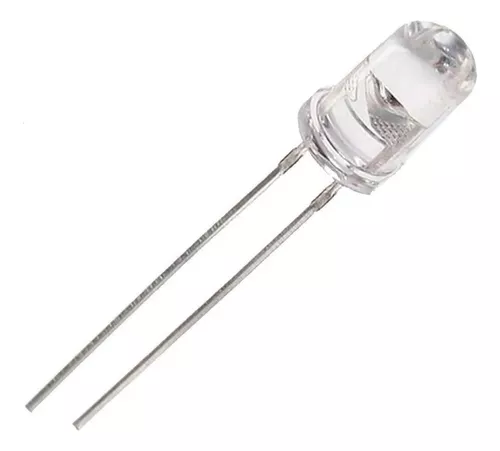
- LEDs (Light Emitting Diodes): Simple output devices controlled via digital signals.
- OLED and LCD Displays: Used for graphical or alphanumeric output, requiring I2C, SPI, or parallel communication.
This has got to be my favourite display, the Nokia 5110.
These are the most common ones, but you can find a lot of exotic electroluminescent devices that display light in creative ways.
Piezoelectric Devices
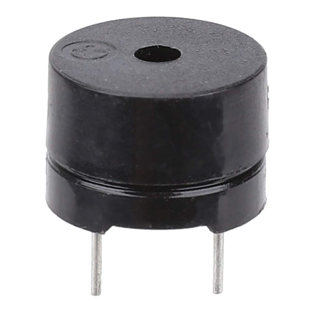
Generate or detect vibrations and sound through piezoelectricity (mechanical stress producing electrical charge). One of the most common out of these devices for generating sound that you'll find in many maker projects is the Buzzer. Its a modules use digital write or PWM for tones.
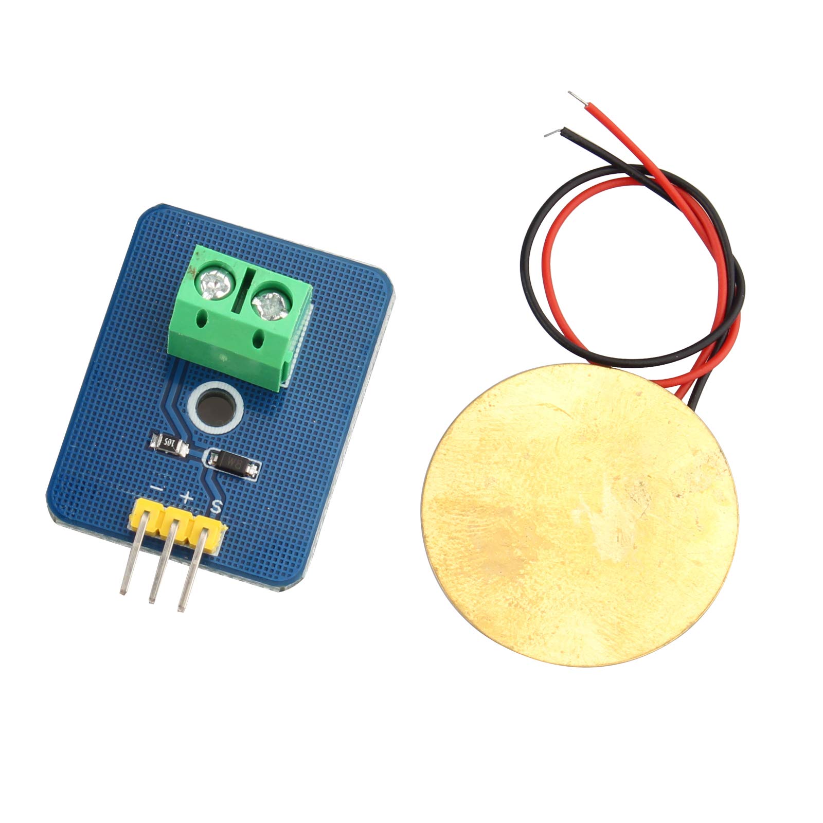
Piezo sensors are also a interesting device, since they can act as both input (detecting vibration) and output (producing sound) and they are easy to make.
Types of Signals for Output Devices
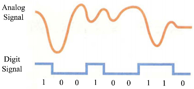
Output devices are controlled using different signal types, which determine how they operate. These signals can be continuous (analog) or discrete (digital), affecting brightness, speed, sound, or motion precision.
Analog vs. Digital Control
-
Digital Write (HIGH/LOW): Simple ON/OFF control for LEDs, buzzers, and relays.
-
Analog Write (PWM): Simulates variable output levels using fast switching signals. Used for dimming LEDs and controlling motor speed.
PWM (Pulse Width Modulation)
Modulates power by rapidly switching between ON and OFF states. Duty Cycle (%) determines how long the signal stays HIGH in a cycle (e.g., 50% duty cycle means the output is ON half the time).
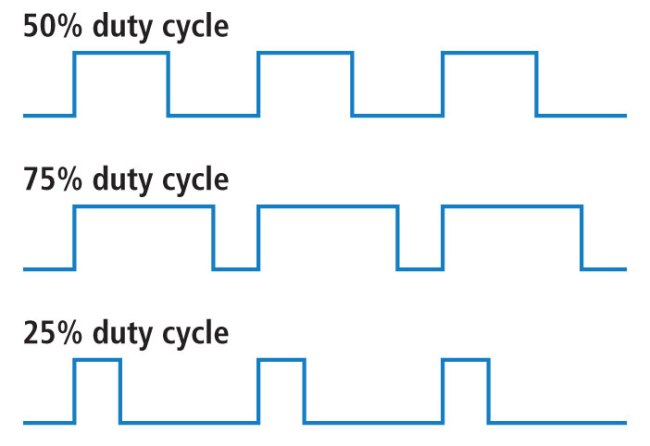
Applications: LED brightness control, motor speed regulation, servomotor positioning.
PID Control (Proportional-Integral-Derivative)
Advanced control system for precise output regulation (e.g., motor speed, temperature control). Uses feedback to adjust signals dynamically.
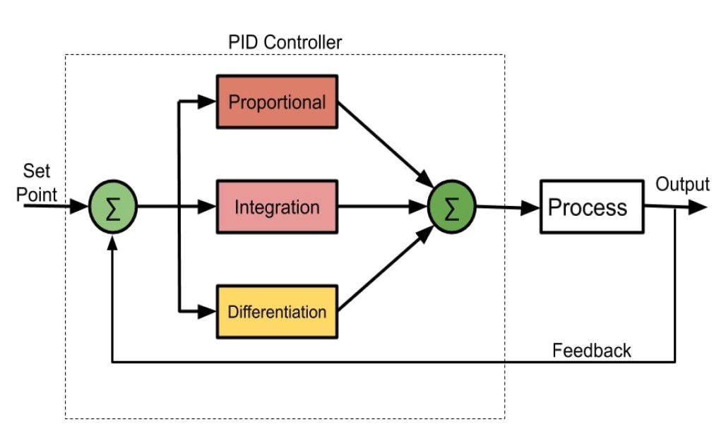
Applications: Robotics, CNC machines, and cool [self-balancing systems](https://www.youtube.com/watch?app=desktop&v=K-F_T59ZDPw&t=3s).
Let's pick an output to play with. Got it.
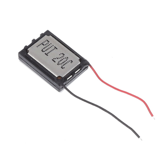
I'll go for this small speaker I found in our lab, the AS01508MO-SP11-LW25-R and program it with the Barduino.
I most admit I have a soft spot for small components, and this looks just about the right size for any of the project I imagine.
To integrate audio playback, I am using the DFPlayer Mini alongside the AS01508MO-SP11-LW25-R speaker.
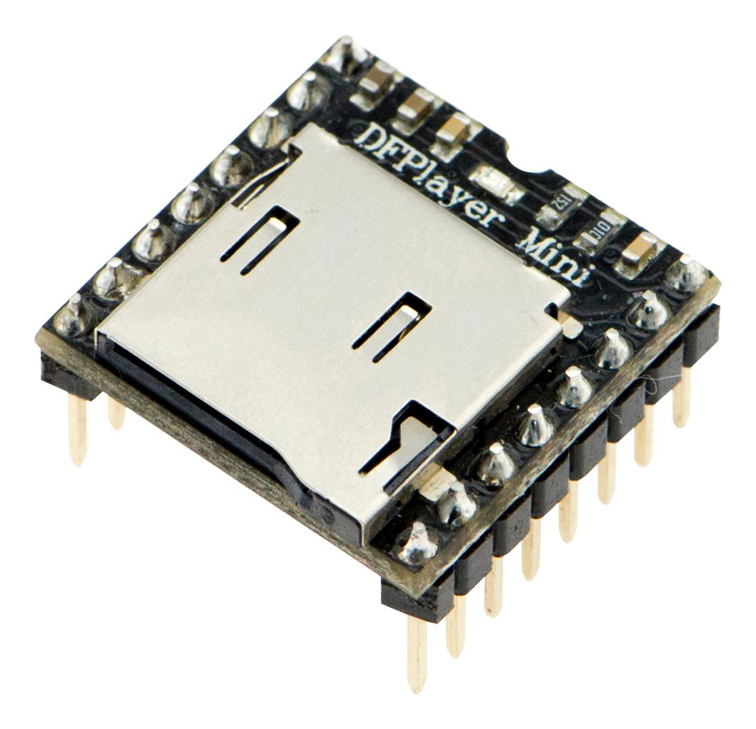
From what I read the DFPlayer Mini is essential for several reasons:
-
Audio Storage & Playback: It allows me to store MP3/WAV files on a microSD card and play them directly, making it a convenient solution for handling music or sound effects.
-
Built-in Amplifier: The speaker requires an amplified signal to produce sound. The DFPlayer Mini has a built-in 3W amplifier, eliminating the need for an external amplifier circuit.
-
Efficient Processing: Instead of making the Barduino process and generate audio signals, the DFPlayer Mini takes care of everything, ensuring smooth performance.
-
Easy Control via UART: The Barduino communicates with the DFPlayer Mini over serial (UART), making it easy to send commands for playing, pausing, or adjusting volume.
What is Serial Communication?
It’s a way for devices to send data one bit at a time over a wire. UART (Universal Asynchronous Receiver-Transmitter) is a common hardware protocol for serial communication.
A UART connection has two important pins:
-
TX (Transmit): Sends data.
-
RX (Receive): Receives data.
Each UART needs to connect TX → RX and RX → TX between two devices.
So according to the pinout here is were we would find these:

I assigned RX and TX pins in my Barduino as the 12 & 13 in the code by listing it in this line:
 // Serial2.begin(9600, SERIAL_8N1, MYPORT_RX, MYPORT_TX);

  Serial2.begin(9600, SERIAL_8N1, 12, 13);
You can access the full code Here, it's a modified example I downloaded from this tutorial that I followed to get the component running.
This is how my wiring looked like:

Unfortunetly it didn't work :(. Nothing was playing so I went into debugging mode. ᕙ(⇀‸↼‶)ᕗ
Debugging
Debugging is the process of finding and fixing errors (bugs) in the code or circuit. It involves systematically checking for issues, testing different parts, and making corrections.
A good approach is to isolate the problem (code or hardware), test step by step, and change one thing at a time to see what fixes the issue.
-
Code Debugging – Checking for syntax errors, incorrect logic, or missing components in your program. Using Serial.print() helps track what’s happening.
-
Circuit Debugging – Ensuring wires, components, and power connections are correct. A multimeter can help verify voltages and continuity.
Let's start by debugging the SD Card. I followed the steps listed in this guide to format the SD Card in a DFPlayer Mini-Compliant Structure.
I went ahead and checked mine only to find that it was set to FAT32 by default.
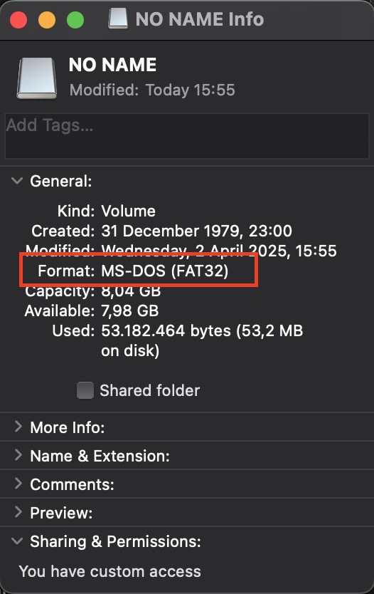
I made sure to name de song file in a way it was the easiest for the DFPlayer to named the song file regonize it. So I put it in a folder named "01" where it would find a song names as "001.mp3".

Well... I found out the one I had was broken/burnt. So I'd like to point this out from the datasheet.
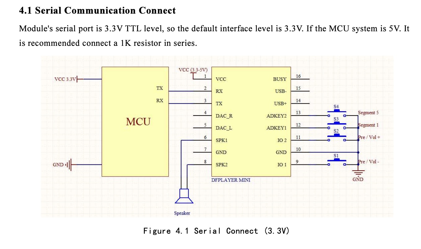
Took another using the DFPlayer standalone mode, powering it through an MCU but turning it on by making contact IO1 and IO2 for simple previous/next control.
Yeiiiiii :) Now that this part is complete, I want to make things a bit more interesting. I'll add a tilt switch and an LED that lights up when the board is upside down. When the board is upright, the DFPlayer will activate instead.
I made it work using the following code.
#include
#include

#define DFPLAYER_RX 2  // PA1 - connect to DFPlayer TX
#define DFPLAYER_TX 3  // PA2 - connect to DFPlayer RX
#define TILT_PIN 4     // PA3 - one leg to GND
#define LED_PIN 0      // PA7 - LED anode, cathode to GND via resistor

SoftwareSerial mySerial(DFPLAYER_RX, DFPLAYER_TX);
DFRobotDFPlayerMini dfplayer;

bool playing = false;

void setup() {
  pinMode(TILT_PIN, INPUT_PULLUP);  // Tilt switch with internal pull-up
  pinMode(LED_PIN, OUTPUT);         // LED pin
  digitalWrite(LED_PIN, HIGH);      // LED on by default

  mySerial.begin(9600);
  if (!dfplayer.begin(mySerial)) {
    // DFPlayer failed to initialize
    while (true);  // Halt here, maybe blink LED if needed
  }

  dfplayer.volume(20);  // Set volume (0 to 30)
}

void loop() {
  bool tilted = digitalRead(TILT_PIN) == LOW;

  if (tilted && !playing) {
    dfplayer.play(1);           // Play 001.mp3
    digitalWrite(LED_PIN, LOW); // Turn off LED
    playing = true;
  } else if (!tilted && playing) {
    dfplayer.stop();            // Stop music
    digitalWrite(LED_PIN, HIGH); // Turn on LED
    playing = false;
  }

  delay(200);  // debounce delay
}
You can access the arduino file here.
And as promissed, last week's inputs with added outputs <3
You can download the code here.
Thank you for catching up! See ya.