Week 2
CAD Computer-Aided Design*** is a technology that uses computer systems to assist in the creation, modification, analysis, or optimization of a design. CAD is widely used in various industries, including engineering, architecture, graphic design, and digital art.
We are going to divide the contents into 2D models and 3D models.
Vector vs. Raster (Pixel) Graphics
- Vector Graphics: Images created using mathematical equations that define geometric shapes such as points, lines, and curves. These graphics are resolution-independent, meaning they can be scaled infinitely without losing quality.
- Raster (Pixel) Graphics: Images composed of individual pixels (tiny squares of color). Raster graphics are resolution-dependent, meaning their quality degrades when scaled beyond their original resolution.
| Feature | Vector Graphics | Raster (Pixel) Graphics |
|---|---|---|
| Composition | Paths and equations | Grid of pixels |
| Scalability | Infinitely scalable without quality loss | Loses quality when enlarged |
| Best Use Cases | Logos, illustrations, typography, technical drawings | Photos, textures, complex digital paintings |
| File Formats | SVG, AI, EPS, PDF | JPEG, PNG, BMP, TIFF |
| Software Examples | Adobe Illustrator, Inkscape, CorelDRAW | Adobe Photoshop, GIMP, Krita |
Why Raster Graphics Are Still Important
Real-world images, such as photographs, textures, and highly detailed illustrations, rely on a pixel-based structure for raster graphics. Why? because if you want to communicate visual data to a machine you need to convert it simpler numberical format for it to interpret it a "do-able" design.
Vector and raster graphics complement each other
Graphic Softwares
Raster (Pixel-Based) Tools
- GIMP (Open-source)
- Krita (Open-source)
- Adobe Photoshop
- Pixlr (Freemium)
Vector-Based Tools
- Inkscape (Open-source)
- Adobe Illustrator
- CorelDRAW
- Linearity Curve
- Vectr (Freemium)
- DrawSVG (Open-source)
Vector models are widely used across different application domains. While all vector tools operate on the same fundamental principles, they often differ in file formats and how they interpret vector data.
My Preferred Vector Tool: Adobe Illustrator
AIAdobe Illustrator* is a professional vector graphics editor developed and marketed by Adobe Systems. It is widely used for digital illustration, technical drawing, and graphic design.
I've been using Illustrator for years now, and it’s a core part of my workflow. I use it to translate hand-drawn sketches into digital designs, create and refine vectors, design svg.Scalable Vector Graphics* files and even convert them into 3D objects. It also comes in handy for presentations, image editing, and tracing images when I need to work with existing graphics.
Almost every project I take on requires me to use it in some way, and it has always been up to the task. It’s a tool I rely on daily, and I couldn’t imagine my work without it.
Other Noteworthy Tools
Among the vector tools discussed in class, Inkscape stands out. I experimented with it during class and created a simple drawing. Here is a portrait of our local dalmatian at the lab.
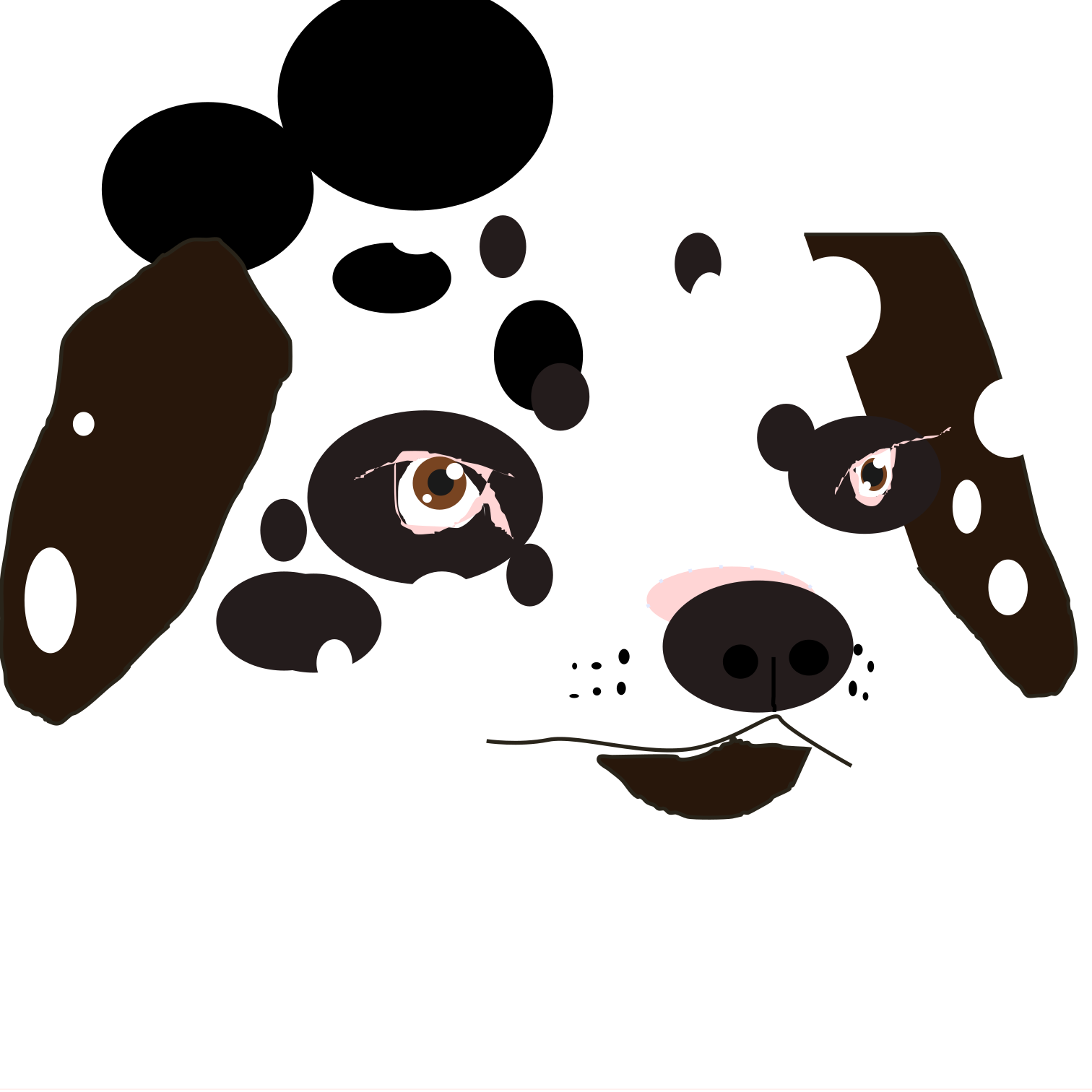
However, learning a new tool with a different workflow requires time and effort to adapt.
Computer-Aided Drafting Tools
CAD Computer-Aided Design*** tools are specialized software used for creating precise 2D and 3D drawings, commonly applied in engineering, architecture, and industrial design. These tools allow users to draft complex technical designs with accuracy, making them essential for professionals working with blueprints, schematics, and construction plans.
Image Editing & File Optimization Tools
- TinyJPG (Compresses images to reduce file size)
- ImageMagick (Command-line image processing tool)
These tools are crucial for optimizing images, reducing file sizes, and improving workflow efficiency.
Image Compression with ImageMagick
To quickly resize and compress images, I used the following command:
convert input.jpg -resize 800x -quality 85 output.jpg
What this does:
- Resizes the image to a max width of 800px while maintaining aspect ratio.
- Reduces quality to 85% for a good balance between clarity and file size.
For batch processing multiple images in a folder:
mogrify -resize 800x -quality 85 *.jpg
This automatically optimizes all .jpg Or any other image file format* files in the directory.
Video Compression & Optimization
To document my workflow efficiently, I recorded a video and used FFmpeg to compress it and speed it up. This helps reduce file size while keeping the quality good for web usage.
I used the following command to achieve this:
ffmpeg -i sculpting.mov -filter:v "setpts=0.33*PTS" -vcodec libx265 -crf 35 -preset ultrafast -acodec aac -b:a 64k output_fast.mp4
What this does:
- Speeds up the video
setpts=0.33*PTS– makes it 3× faster. - Compresses using H.265
libx265– reduces file size significantly. - Adjusts quality
-crf 35– balances compression and clarity. - Optimizes audio
aac -b:a 64k– keeps sound at a reasonable bitrate. - Uses ‘ultrafast’ preset – speeds up encoding.
If I need an even faster video, I can tweak setpts e.g., setpts=0.25*PTS for 4× speed.
And off to the 3D Models!
Types of 3D Modeling
In 3D CADComputer-Aided Design* , there are two primary modeling techniques: Mesh Modeling and NURBS Modeling. Each serves a different purpose and is suited for specific workflows.
Mesh Modeling
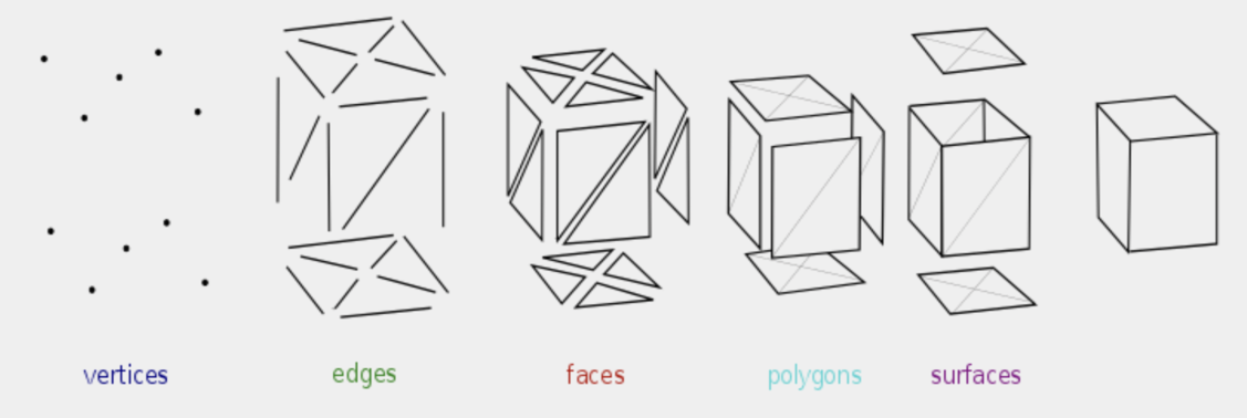
Mesh modeling represents 3D objects using a network of interconnected vertices, edges, and faces. This technique is widely used in animation, gaming, and visual effects due to its flexibility and ease of manipulation.
Key Elements of a Mesh
- Vertices – Individual points in 3D space that define the shape of an object.
- Edges – Straight lines connecting two vertices.
- Faces – Flat surfaces formed by connecting three or more edges, usually forming triangles or quadrilaterals.
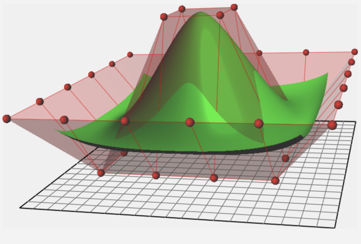
Mesh Subdivision & Object Smoothness
To achieve smoother surfaces, subdivision modeling increases the number of polygonsflat 2D shape with straight sides used to define the surface of 3D objects. Triangles and quads are the most commonly used polygons in mesh modeling.* in a model. This enhances detail and allows for better control over object density.
! However, higher polygon counts result in larger file sizes, which is important to consider when converting NURBS to polygon meshes.
Common formats for mesh-based models include:
- OBJ – A widely used format for 3D objects that stores geometry but lacks animation or texture mapping details.
- FBX – A more advanced format supporting animation, textures, and multiple objects within a scene.
- STLSTL (STereoLithography) is a widely used file format for 3D printing. It represents 3D objects in a triangulated surface format without color, texture, or other CAD features.* – A format commonly used for 3D printing that represents 3D objects as a mesh of triangles, ideal for rapid prototyping.
NURBS Modeling
NURBSNon-Uniform Rational B-Splines* is a mathematical modeling system used to create precise, smooth surfaces. It is commonly used in industrial design, automotive modeling, and CAD applications where precision is critical.
Key Elements of NURBS Modeling
- Control Points – Define the general shape of the curve or surface.
- Nodes – Mathematical points that influence how curves and surfaces interpolate between control points.
Limitations of NURBS Models
NURBS models consist of separate surface patches, making it difficult to connect them seamlessly. While these patches maintain perfect curvature and continuity, they can create workflow limitations when working with complex models.
- Animation Constraint: NURBS objects cannot be directly animated. To animate a NURBS model, it must first be converted into a polygon mesh so that joints can be welded together.
- Seams & Connectivity: NURBS models remain separate from one another, meaning that unless converted to polygons, there will always be distinct seams between surfaces.
Mesh vs. NURBS: Choosing the Right Approach
| Feature | Mesh Modeling | NURBS Modeling |
|---|---|---|
| Structure | Composed of vertices, edges, and faces | Defined by mathematically precise curves |
| Editing Flexibility | Easier to manipulate and modify | Requires precise control point adjustments |
| Animation Compatibility | Fully animatable | Needs conversion before animation |
| Texturing (UV Mapping) | Supports UV unwrapping for detailed textures | Cannot be UV unwrapped directly |
| Best Use Cases | Games, animation, VFX, organic modeling | Industrial design, automotive modeling, CAD precision |
For projects requiring detailed textures and animation, mesh modeling is the better choice due to its flexibility and UV mapping capabilities. However, for highly accurate, mathematically defined surfaces, NURBS modeling is preferred.
Modeling Strategies
Booleans & Operators
Boolean operations involve combining two or more 3D objects using mathematical operations such as union, difference, or intersection. These operations allow you to create complex shapes by merging or subtracting objects.
Extrusions
Extrusion is the process of extending a 2D shape along a third dimension, creating a 3D object. This technique is commonly used in architectural and mechanical design, where profiles are extruded to create walls, beams, or pipes.
Revolution (Curves around Axes)
Revolution modeling involves rotating a 2D profile (a curve) around a central axis to create a 3D object. This technique is used to create symmetric objects like bottles, vases, or wheels, where the profile revolves to form the complete shape.
3D Sculpting
3D sculpting is a more organic approach to modeling that mimics the process of sculpting with clay. Artists manipulate the digital model as though they are shaping a physical object, often used for characters, creatures, and other complex organic forms.
2D Sketching and Descriptive Geometry
2D sketching is used to lay the groundwork for 3D models by defining the basic shapes and outlines of an object. Descriptive geometry refers to the use of 2D views (e.g., top, front, side) to represent and understand the 3D structure of objects, helping designers visualize spatial relationships.
Box Modeling
Box modeling is a technique where a simple 3D shape, usually a cube or box, is subdivided and refined into a more complex model.
Meshes
Mesh modeling, as described earlier, uses a network of vertices, edges, and faces to create 3D objects. Meshes are highly versatile and are essential for creating both hard surface and organic models.
Parametric Design
Parametric design involves creating 3D models based on a set of parameters or rules. The model can automatically adjust when these parameters are changed, making it ideal for products that require customization, such as architectural components, mechanical parts, or industrial designs.
Textures
A texture map is an image applied to the surface of a 3D model to give it color, detail, and realism. It is essentially a 2D representation of a model’s surface, wrapped around the 3D geometry using UV mapping.
UV mapping is the process of unwrapping a 3D model’s surface to a 2D plane, similar to how a paper model is unfolded. It allows the texture to be correctly applied across the model’s surface.
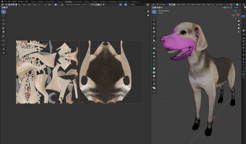
Proper texture mapping is crucial for achieving realism in 3D modeling, as it helps simulate complex surfaces like fabric, skin, metal, or stone.
Each of these modeling strategies offers different advantages depending on the nature of the project. For example:
- Boolean and extrusion operations are often used in mechanical design for creating precise, engineered objects.
- 3D sculpting is better suited for creating more fluid, organic models, like characters.
- Parametric design provides flexibility in engineering and product design, allowing for quick alterations to models based on changing parameters.
3D Modeling Software We Tried in Class
- Rhinoceros 3D (Rhino)
- Blender (Open-source)
- OpenSCAD (Open-source)
- Grasshopper (Plugin for Rhino)
- Autodesk Fusion 360 (Freemium)
My Preferred 3D Modeling Tool: Blender
After trying different modeling software, Blender remains my tool of choice. Its open-source nature, extensive capabilities, and strong community support make it an essential part of my workflow. How?
- Offers a powerful polygon modeling workflow suitable for both organic and hard-surface modeling.
- Includes sculpting tools that allow for detailed artistic control.
- The built-in UV mapping and texturing tools make it easier to create detailed materials.
- Features an integrated rendering engine (Cycles & Eevee) for high-quality visuals.
- Supports animation and rigging.
And this is only a fraction of it. I still have a long way to go discovering its features. Whether for personal projects or professional work, Blender's flexibility allows me to approach 3D modeling in a way that fits my creative needs.
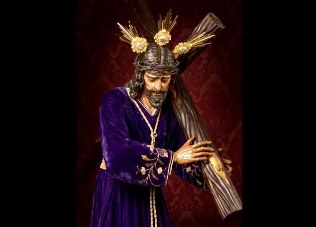
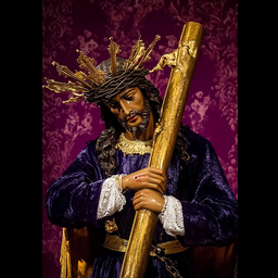
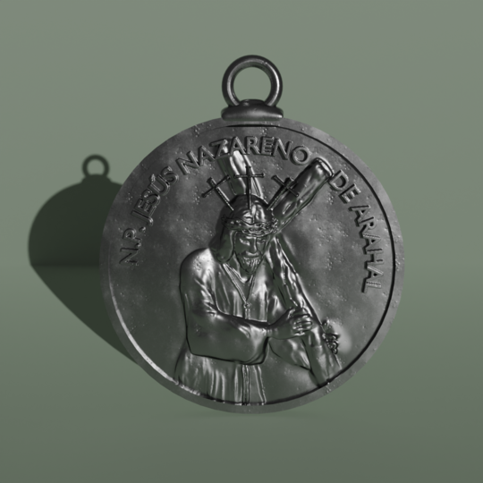
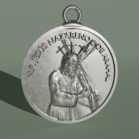
As mentioned in my bio (About Me), I am a freelance jewelry designer. I specialize in taking custom requests, and this week, I had to work on designing a religious stamped medal.
The client provided the following specifications:
- Diameter of the medallion: 23 mm
- Width of the outer bezel with relief: 1.5 mm
- The name to be engraved on the edge in relief: "N.P. JESÚS NAZARENO DE ARAHAL"
I was also provided with a set of reference images
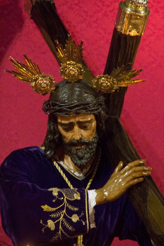

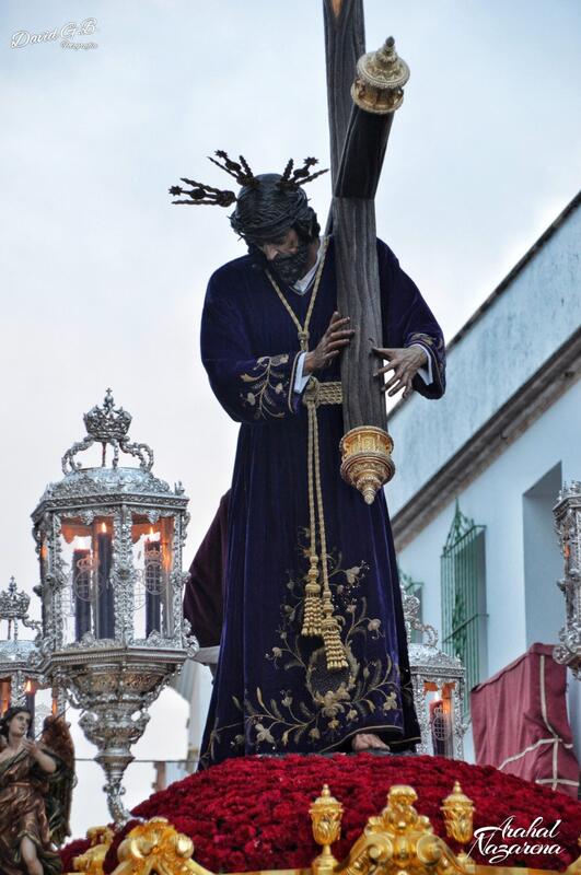

I proceeded to combine them with an AI tool called MidJourney to combine them and created this one:
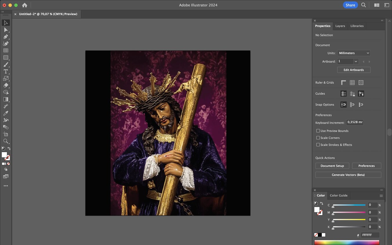
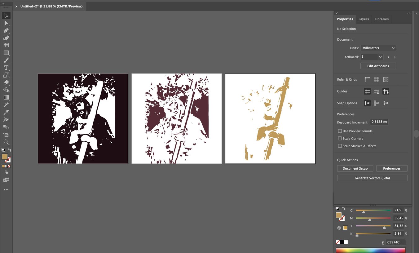
Then I began my usual process. I opened a new file on Illustrator and Placed Shift ⇧ ⌘ P the reference image Place command will open the browser to find de file* ,
Selected (V) the image and in the Properties tab I picked Image Trace and I applied the "3 colors" tracing.
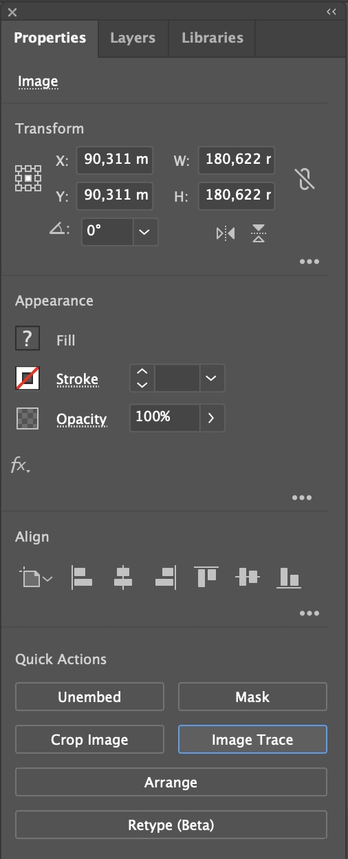
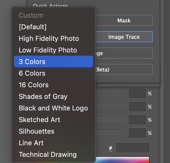
Image Trace in Illustrator converts raster See previously mentioned content* images (like photos) into editable vector graphics by creating paths that replicate the image's shapes and colors.
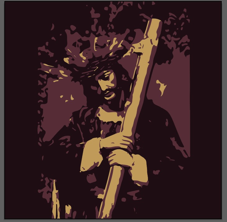
When I selected the 3-color option, Illustrator grouped the darkest areas into one set of shapes with the same fill color, while the mid-gray and lighter areas were assigned their own groups.
As a result, my image now looked like this:
Now, my image was vectorized with grouped shapes. However, I wanted to separate them by color. To do this, I clicked Expand,
then selected (V) my image again and used Ungroup Shift ⇧ ⌘ G to separate the shapes.
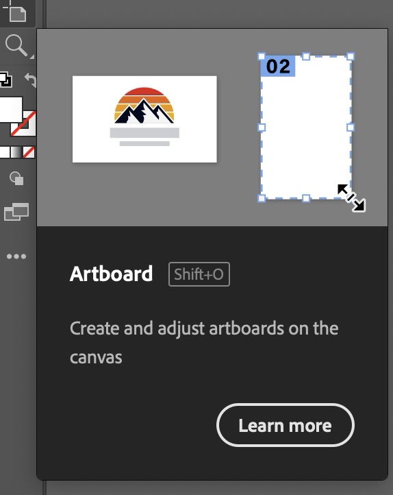
Next, I used the Select tool (V) again to box-select everything on my artboard. Then, I used the Artboard command Shift ⇧ O to duplicate the image, creating three copies.
I selected (V) one random shape and went to the Select tab above * and clicked on >Same >Fill color.
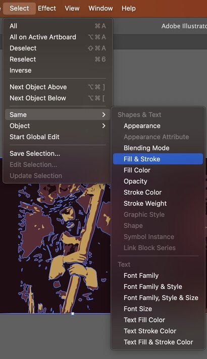
I did this with the three colors and deleted the ones I didn't need so that my artboards could cointain one color each:
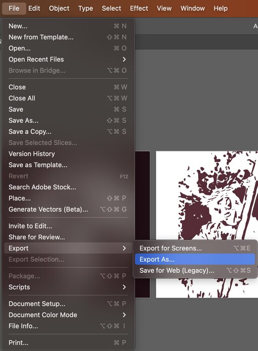
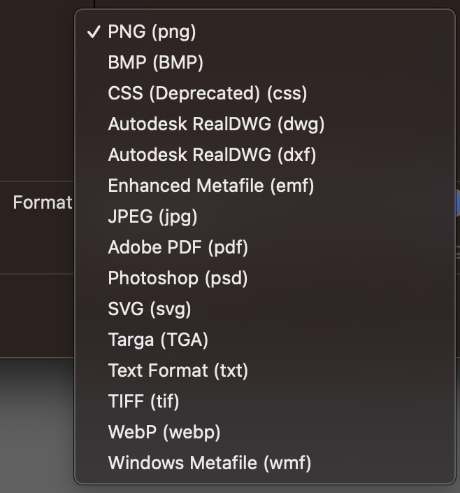
All set! now I exported them as svg. files this way, >File >Export >Export as. Then you can name the file and choose the format you want to save it in, in my case; svg..
Getting into Blender!
At this stage I had a meeting with the client and discussed a different aproach. Instead of taking the svg. files to create a new idea, I was asked to sculpt directly over one of the reference images.
First I imported the image as Image Reference following this very recommended tutorial. And now I had this on my canvas after adding Shift ⇧ A a cylinder to model on:
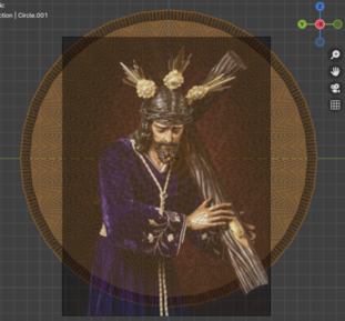
Next, I made sure to apply Scale ⌘ A and added a Remesh Modifier.
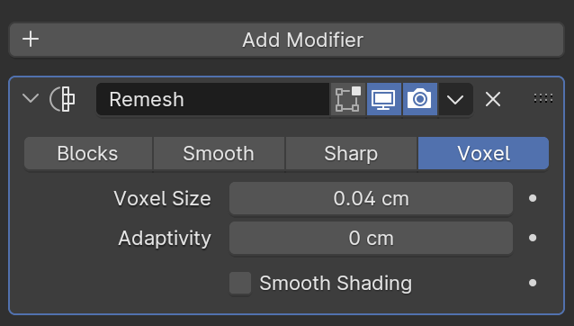
Why was this necessary for sculpting?
The Remesh modifier non-destructive tool that allows you to change an object’s shape or properties without permanently altering its base geometry * helps create a uniform topology, ensuring cleaner, more detailed sculpting without stretching or distortion. Without it, sculpting on the default geometry could lead to uneven details or artifacts.
Ok, I hopped into Sculpt Mode,
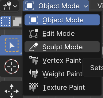
and made my way to the finish result using the sculpt tools.
A peek into my workflow ;)
The tools I use the most are;
- Draw – Adds or removes material like a digital clay brush, perfect for general shaping.
- Smooth – Softens rough areas by evening out the surface, essential for cleanup.
- Grab – Moves large portions of the mesh without changing topology, useful for shaping.
- Mask – Allows you to hide parts of the model so you can work on specific areas without affecting the rest.
- Inflate – Expands or contracts the selected mesh, great for adding volume or pushing areas out.
All set!
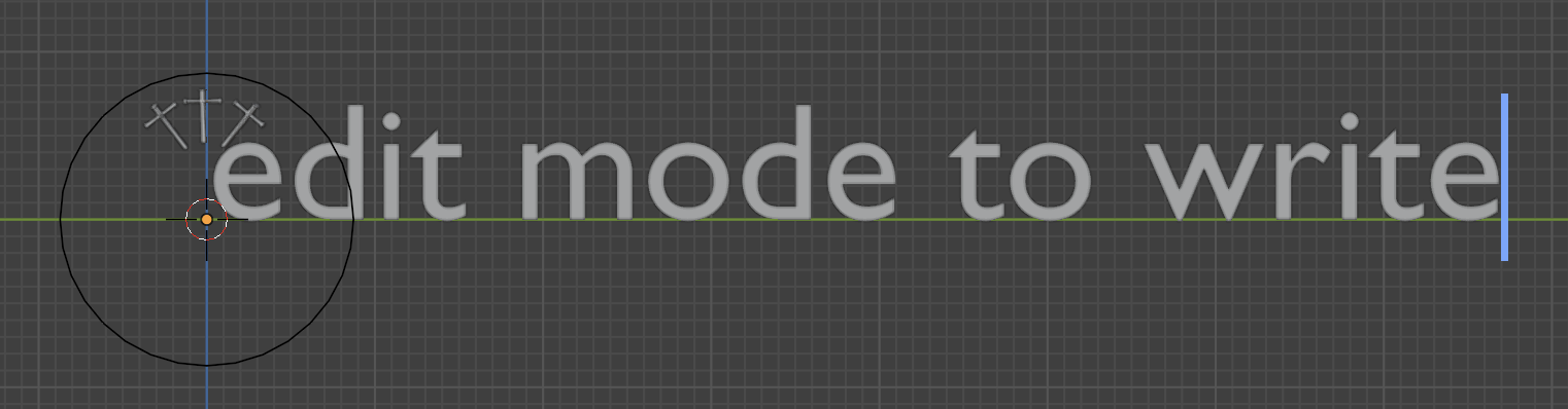
You may have noticed the text... I did this by adding Shift ⇧ A a Text and switching to Edit Mode to be able to write.
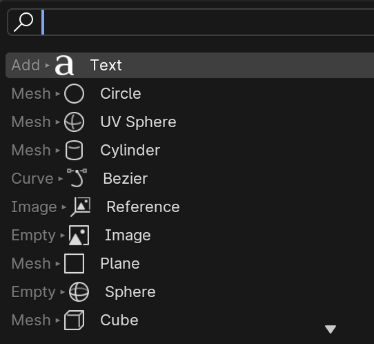
I also added Shift ⇧ A a circle Curve and selected the text and went to its properties.
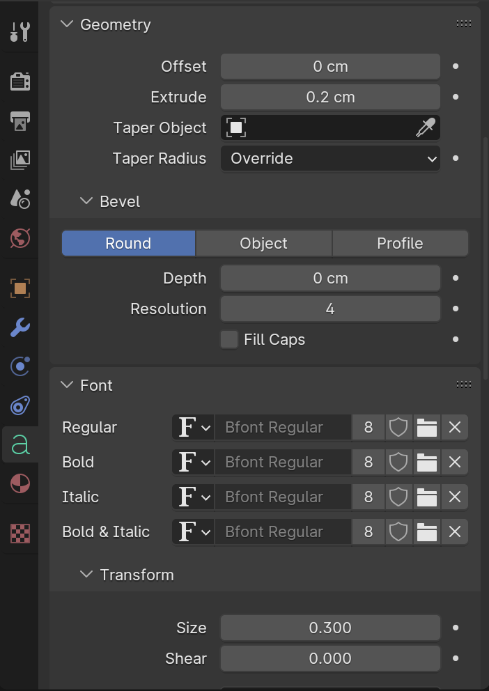
I used tapper object to select the circle curve so that text could follow along the curvature.
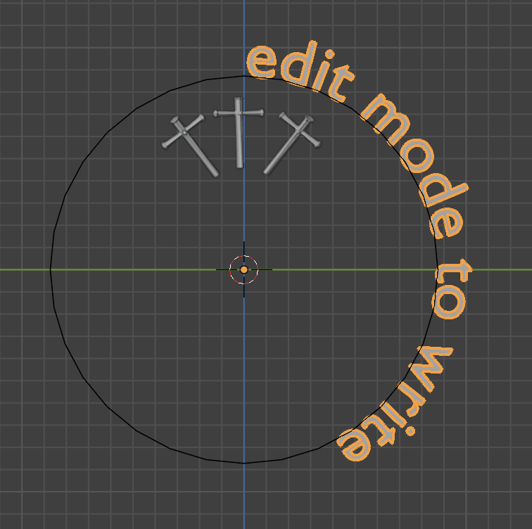
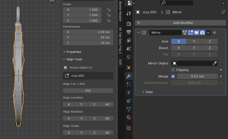
Next step was to mirror the textured side and add some crosses. So I went over to properties and added a mirror modifier.
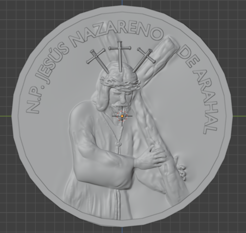
Added some final details and rendered the scene to make it look like this:
Remember you can find both the Illustrator file and the Blender file here.
And that's about it! You'll see me using these tools for the rest of the program. I find them really powerful and inspiring.