Week 7
This week the focus was set on Computer Controlled Machining, introducing us to CNC* Computer Numerical Control milling, a subtractive manufacturing process that allows for precision cutting and shaping of large materials such as wood, plastics, and some metals. The primary goal was to understand how to design for CNC milling, generate toolpaths, and safely operate a CNC router.
CNC Milling and Types of CNC Machines
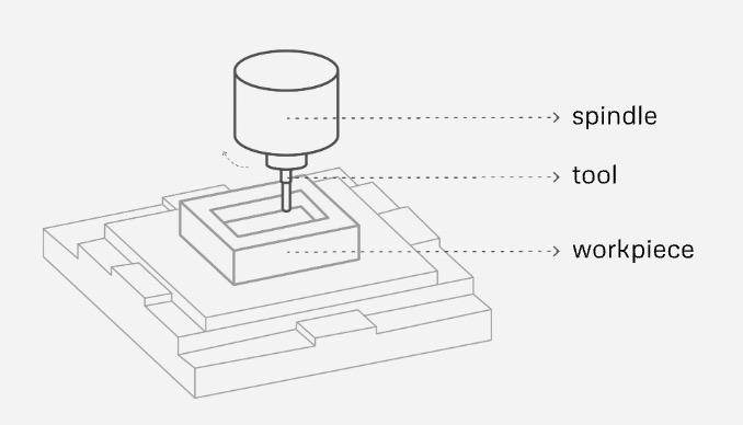
CNC milling is a process where a spinning rotary cutter removes material from a workpiece to shape it according to a digital design. This is the anatomy of the a basic CNC:
Different types of CNC machines are used depending on the complexity and scale of the project:
- CNC Routers: Used for cutting wood, plastics, and soft metals; ideal for 2D and 3D shaping.
- CNC Milling Machines: More rigid and precise, often used for metalwork.
- Plasma Cutters: Cut through metal by using a high-temperature plasma arc.
- Laser Cutters: Used for engraving and cutting thin materials with precision.
- Water Jet Cutters: High-pressure water and abrasives cut through almost any material, including metals and glass.
Materials
- Wood (Plywood, MDF, Hardwood) – Affordability and ease of cutting.
- Plastics (Acrylic, HDPE, Delrin) – Used for more durable projects.
- Foam – Lightweight, easy to shape.
- Aluminum – Possible with the right setup and tools but requires careful settings.
Design for Machining
When designing for CNC, considerations must be made for fixtures, cutting strategies, and assembly.
Screw Positions & Bed Positioning
This means ensuring the material is securely placed on the flat surface and does not shift during machining. Some useful fixture strategies include screws, double-side tape, clamps and vacuum beds.
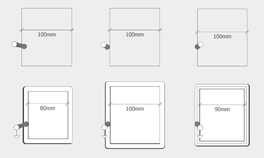
Types of Cuts
- On: Centered on the path
- Out: Outside the closed vector
- In: Inside the closed vector
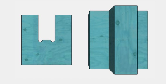
Dog Bone & T-Bone Fillets
This is one the most important aspects of CNC cutting. Because of its very small cutting channel, a laser cutter can produce an inside corner with a sharp angle, whereas a rotary cutter using a physical tool is limited to inside corners rounded at the cutting tool's radius.
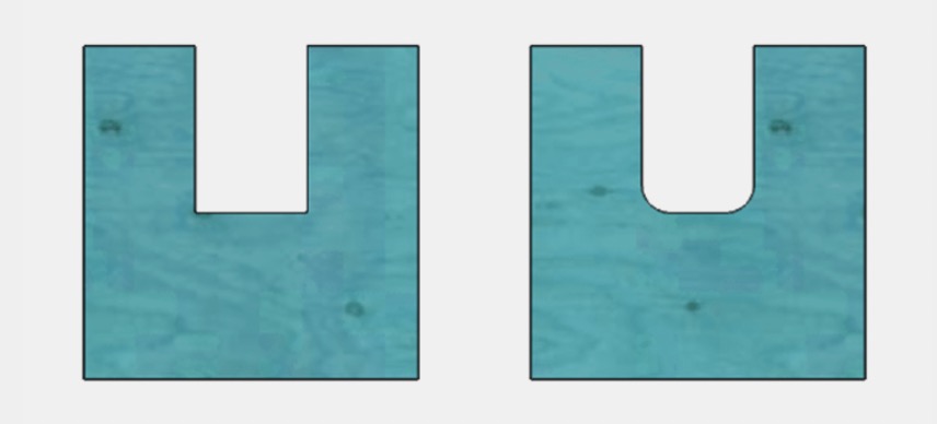
See? These round corners represent a problem when designing joints on pieces that fit together, so to make the tool reach those sharp corners, we leave a small margin using Dog Bone and T-Bone strategies.
 Dog Bone
 T-Bone
Nesting
Nesting is the process of arranging parts efficiently on a sheet to minimize material waste.
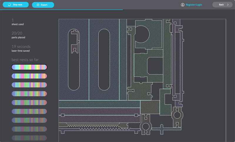
A very useful open source nesting application I recommend is Deepnest. It supports formats like SVG, DXF, and AI, making it compatible with most design and CNC software.
Toolpath & Cutting Strategies
A toolpath referrs to the programmed movement of the cutting tool. For this specific CNC machine, careful planning is essential to ensure efficiency, precision, and high-quality results.
For that to happen, it is important to understand the main cutting tool; Bit. A CNC bit is the rotating cutter attached to the spindle of a CNC machine. It determines how material is removed, affecting cut quality, speed, and precision. Bits come in different shapes and sizes, each designed for specific types of cuts, materials, and finishes.
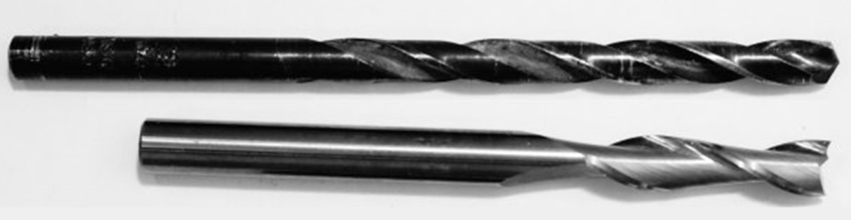
Drill Bits vs. End Mills
- Drill Bits : Only for making vertical holes.
- End Mills: Can cut in multiple directions, including sideways.
Bit Anatomy:
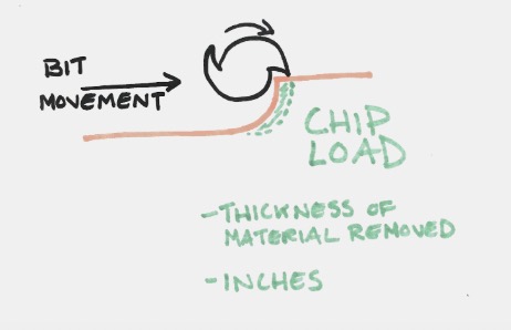
- Flutes: Channels that remove material from the cut.
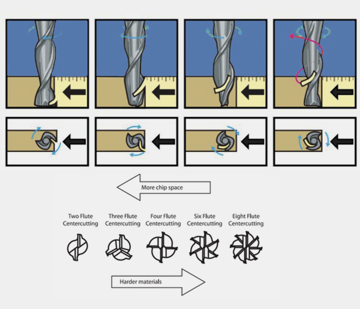
- Chip Load: The amount of material removed per flute per revolution.
Feeds & Speeds
These parameters control how the cutting tool interacts with the material, affecting cutting efficiency, surface finish, and tool longevity
- Feed Rate: How fast the tool moves through the material.
- Spindle Speed: Rotations per minute (RPM) of the cutting tool.
Climb vs. Conventional Cutting
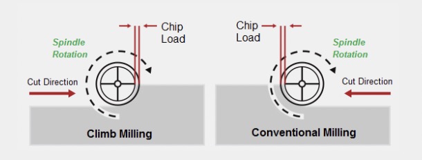
- Climb Cutting: Smoother finish, reduces heat, but requires a rigid machine. -Conventional Cutting: More forgiving but can cause rougher edges. Holding Strategies (Screws & Tabs)
Tabs
Imagine cutting a square, you start from a corner, reach the second, the third, and you are leaving a space where the tool path went through. Now you are reaching the last corner but the square is loose so the bit starts to move around. This is why you need bridges to prevent parts from moving. These are small uncut section to be manually removed afterward.
Safety
! Always wear safety glasses, hearing protection, and a dust mask. Keep hands away from the cutting area.Make sure the emergency stop is accessible. Locate the fire extinguisher available.
AND if you are a long haired person like me, tie your valuable hair. Also avoid hanging accesories and scarfs.
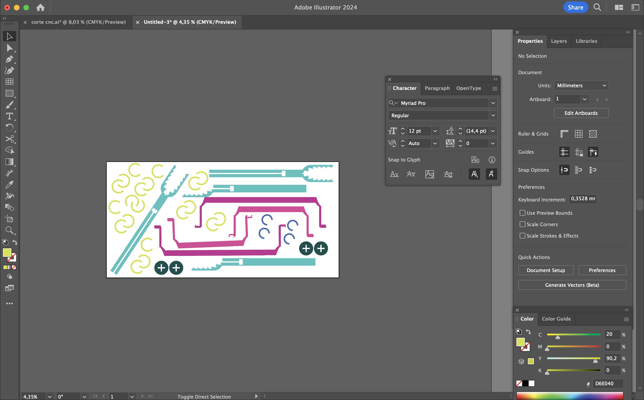
On this week we had to cut a design based on meter-scale dimensions. I decided to build a structure for a castle. After much drawing, I thought it through on a 2D format that I could later assemble. I used Adobe Illustrator for this process.
Here’s what my canvas looked like:
I added some bones.

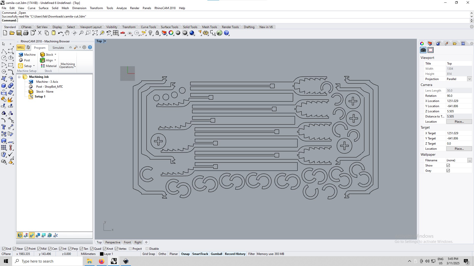
Nested it properly and sent it to RhinoCAM.
Then I showed this to my local instructor and literally laughed on how I did the bones. Then I remembered I don't draw them on the design; I add them on the CAM file as circle paths and calculate the radius based on the size of the mill. -.-
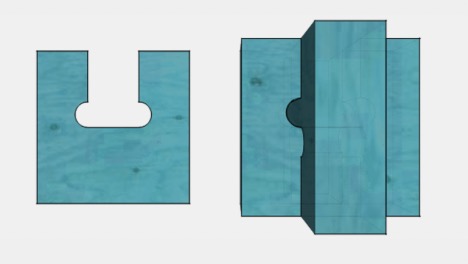
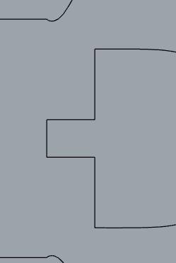
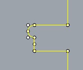
Once in RhinoCam, if this is the shape:
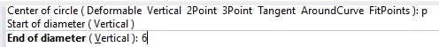
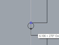
I add a circle to it on the corners by ussing the Circle Command and setting the diameter to 6mm (same as the mill).
Like this.
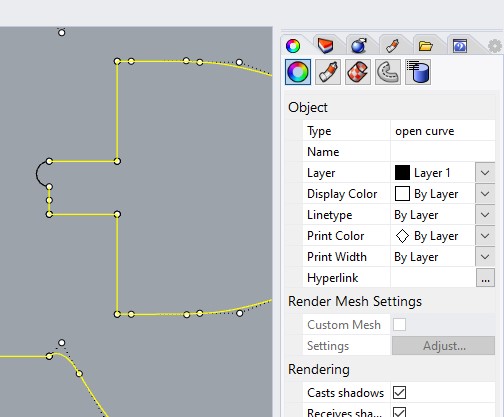
And now I select the shapes,

use Command Trim,
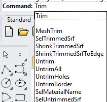
and select the lines I want to remove from the design.
You might notice that the lines stil have different colors. That means they are in different layers.
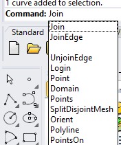
Yet another command, the Join Command will glue these segments together as we need them.
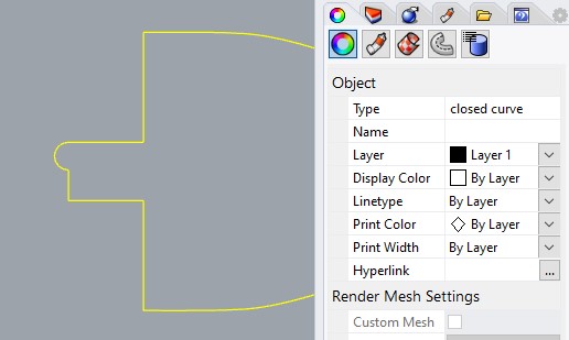
Now you'll see it's a closed curved.
RhinoCAM
RhinoCAM is a plugin for Rhino 3D that allows for CNC toolpath generation and simulation. It is particularly useful for complex 3D milling and creating efficient cutting strategies.
Pocketing & Toolpaths
Pocketing is a strategy where material is removed from a defined area without cutting through the entire workpiece.
Toolpaths define the movement of the cutting tool, ensuring precision and efficiency. CNC Stock Setup
Before machining, it is important to define the size and shape of the raw material (stock) in RhinoCAM. So let's get to it.
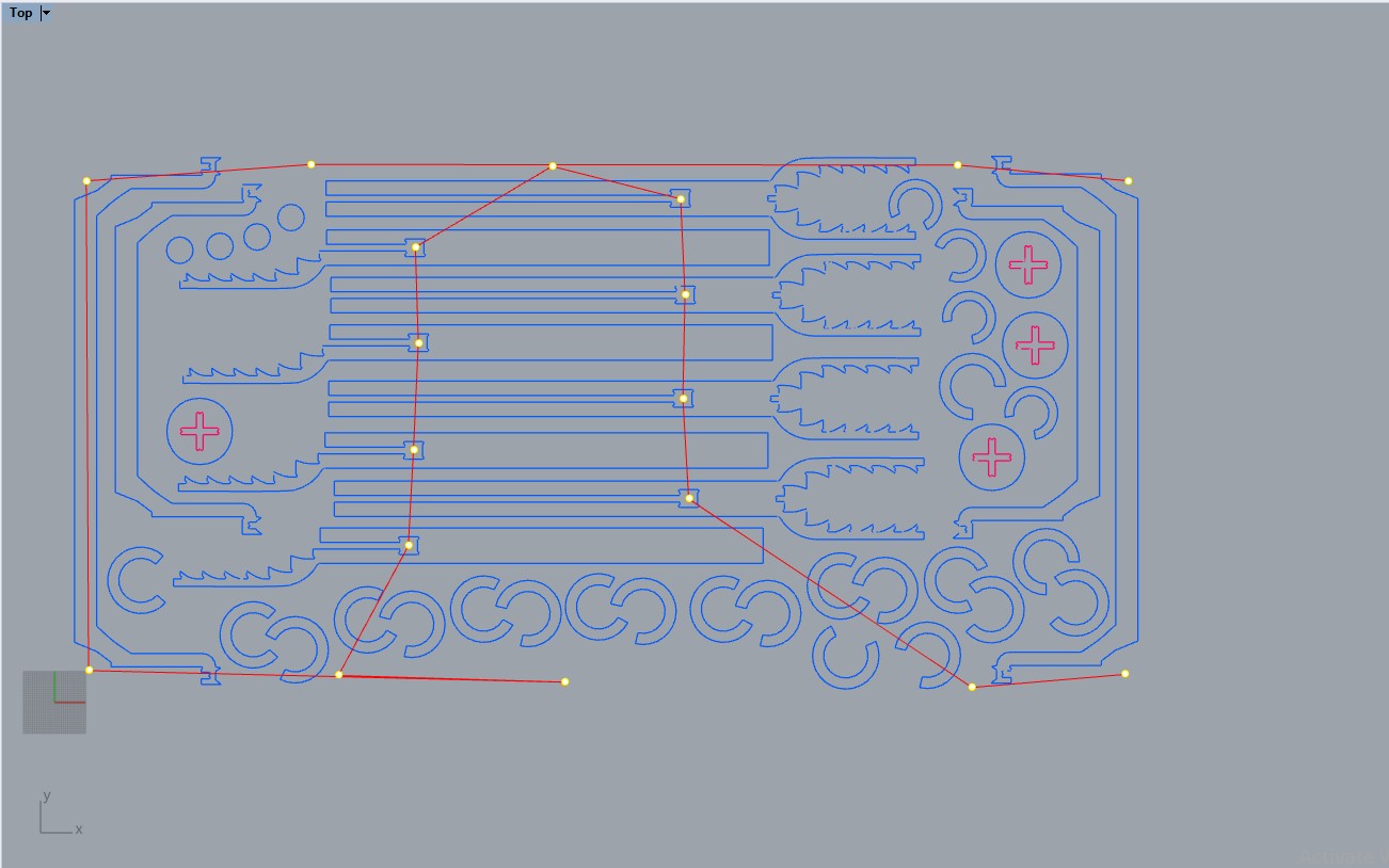
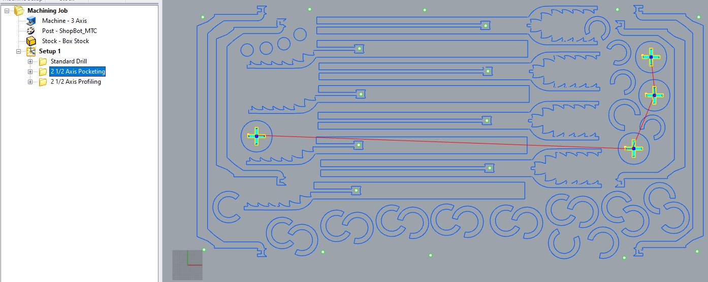
I selected all of the shapes and separeted them by color layers.
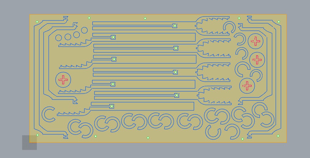
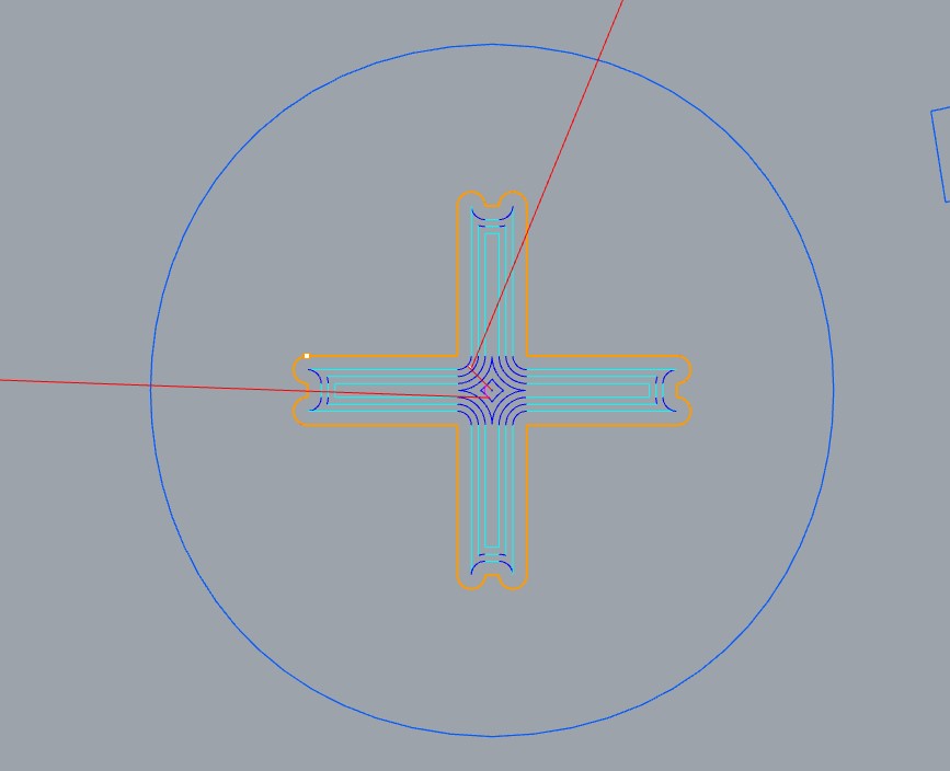
Blue is for a standart milling toolpath and red is for pocketing parts out this way:
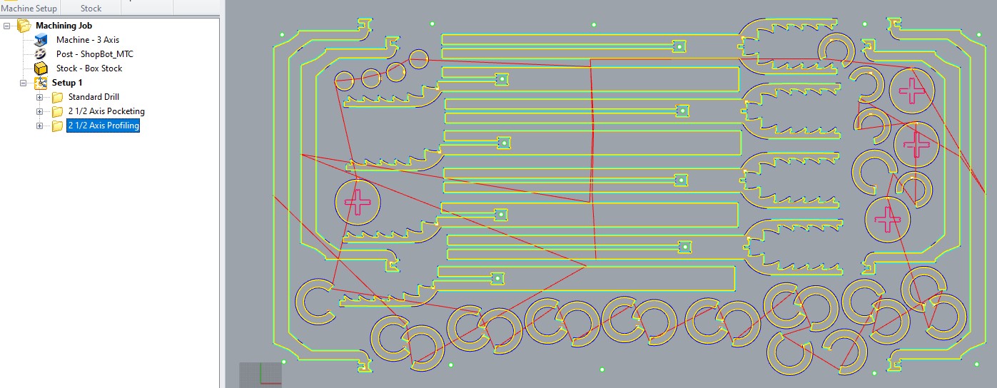
I used the command RhinoCAM2018 and opened the Machining Browser to detail my Machining Job. There I created the Pocketing, Drilling and Profiling folder.
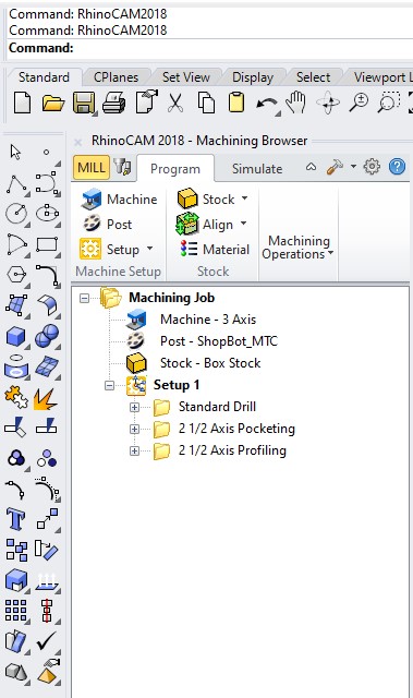
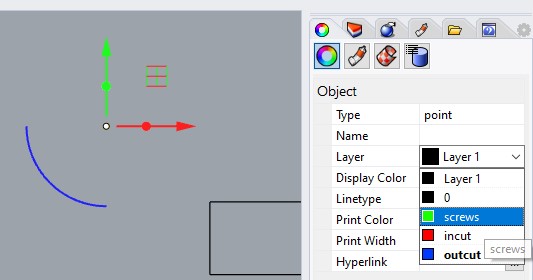
In the Drilling folder, I included the green circles where the tool moves vertically to create holes for screws that secure the material to the table. This prevents any movement or shaking once certain parts are cut and become loose.
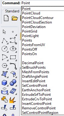
To add these, I use the Point Command and then I assigned the color to the layer.
This is the first toolpath to be executed.
Its settings:
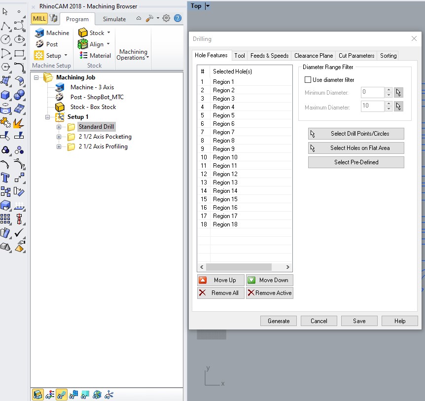 Hole Features
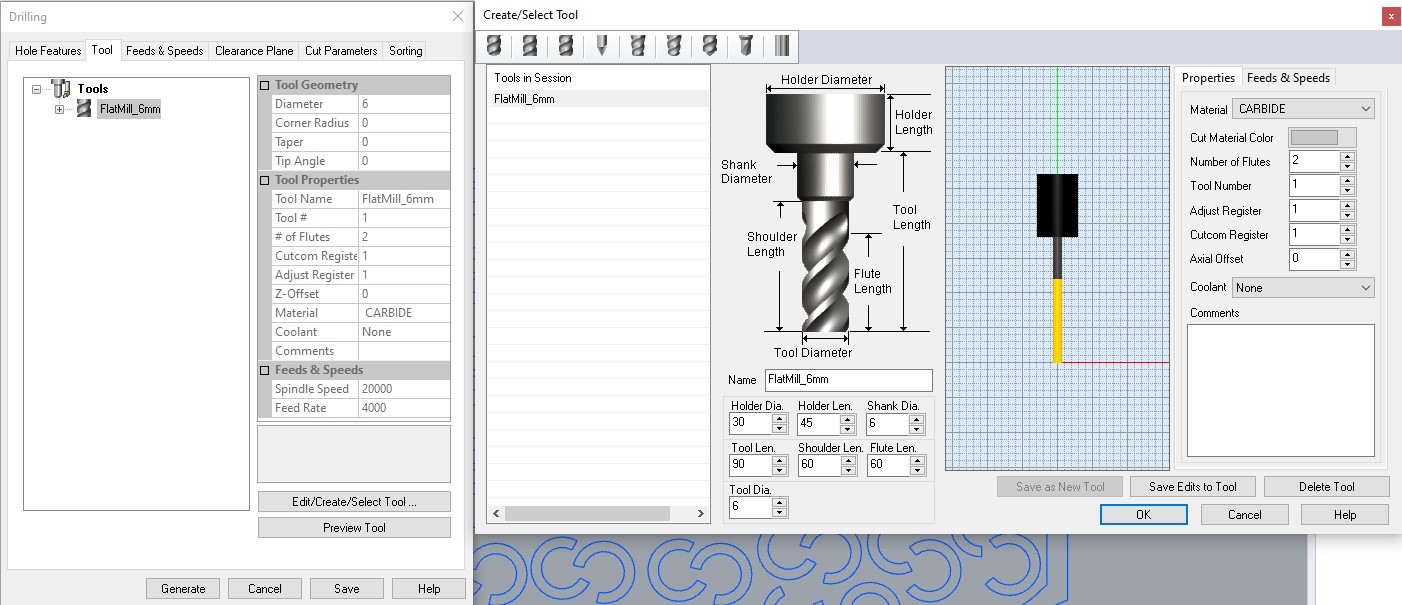 Tool
Tool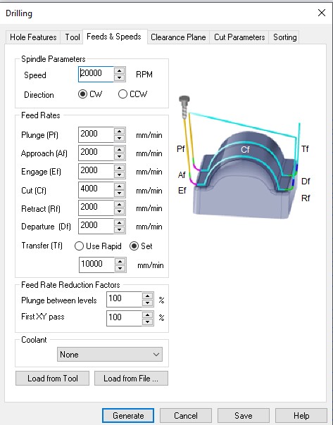 Feeds & Speeds
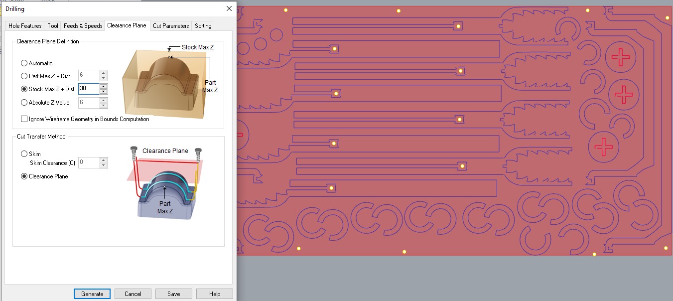 Clearence Path
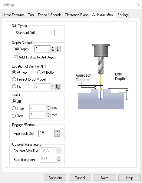
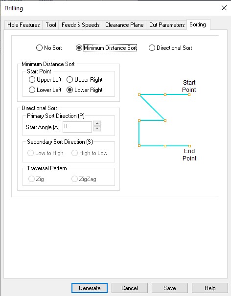 Cut Parameters and Sorting
This was the path for Pocketing:
Its settings:
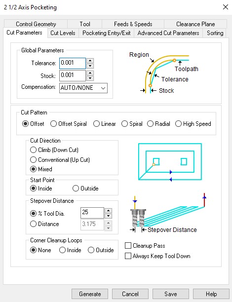
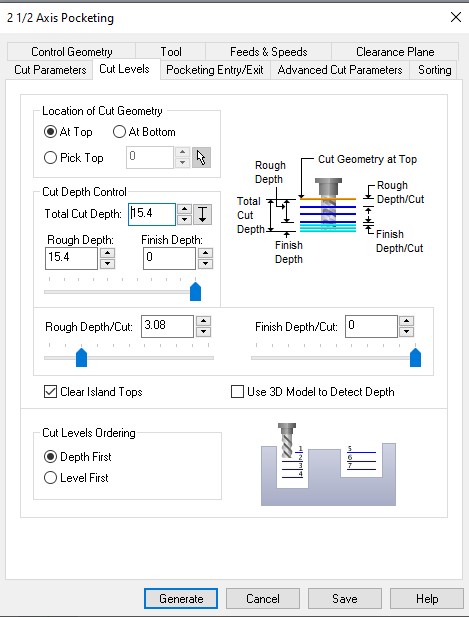 Cut Parameters and Cut Levels
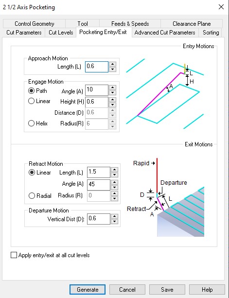
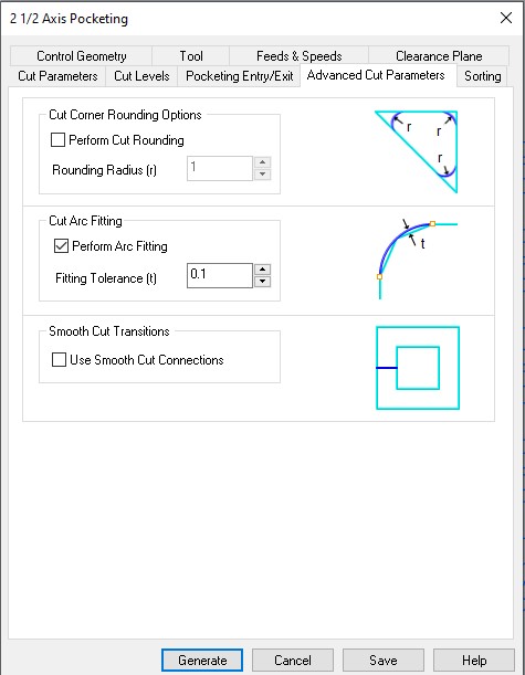 Pocketings Entry/Exit and Advanced Cut Parameters
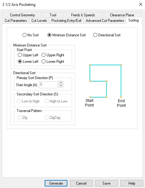
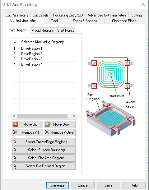 Sorting and Control Geometry
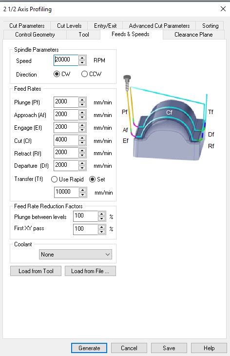
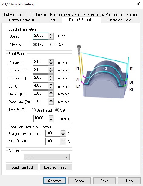 Feeds & Speeds
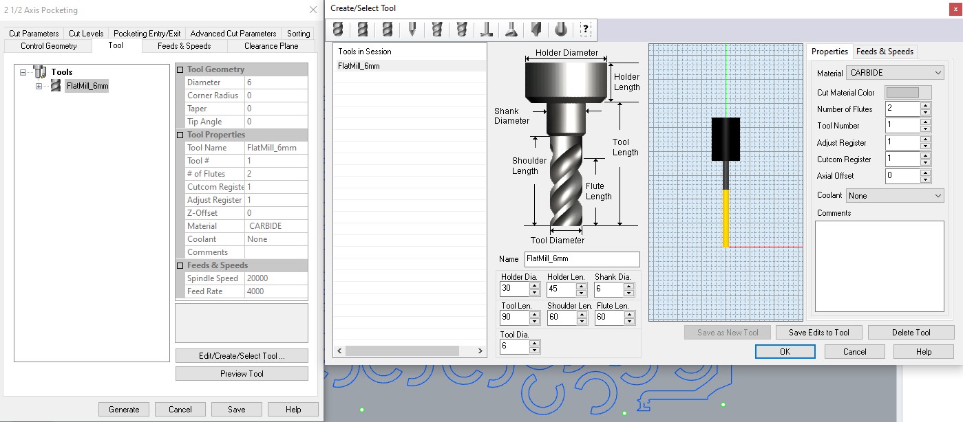 Tool
Tool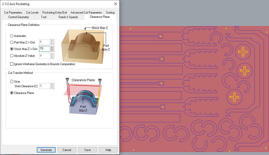 Clearence Plane
And finally, the Profiling Path:
Its settings:
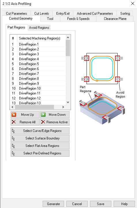
 Control Geometry and Feeds & Speeds
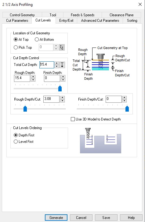
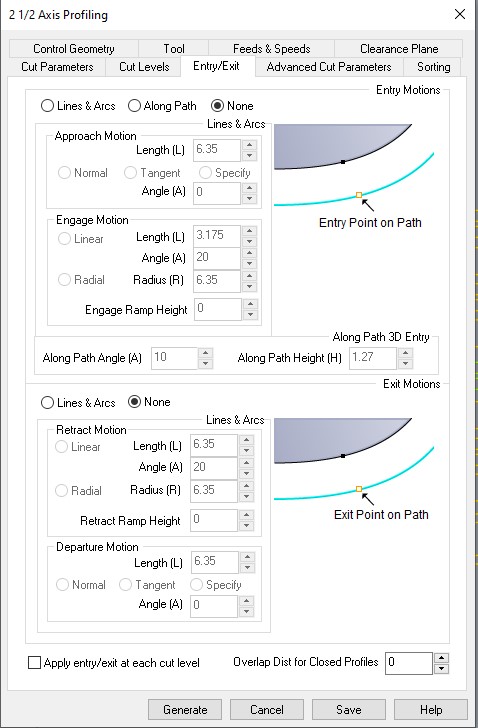 Cut Levels and Entry/Exit
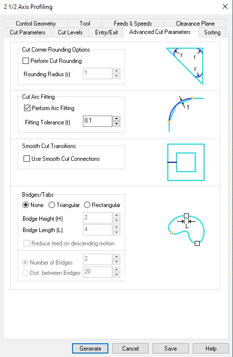
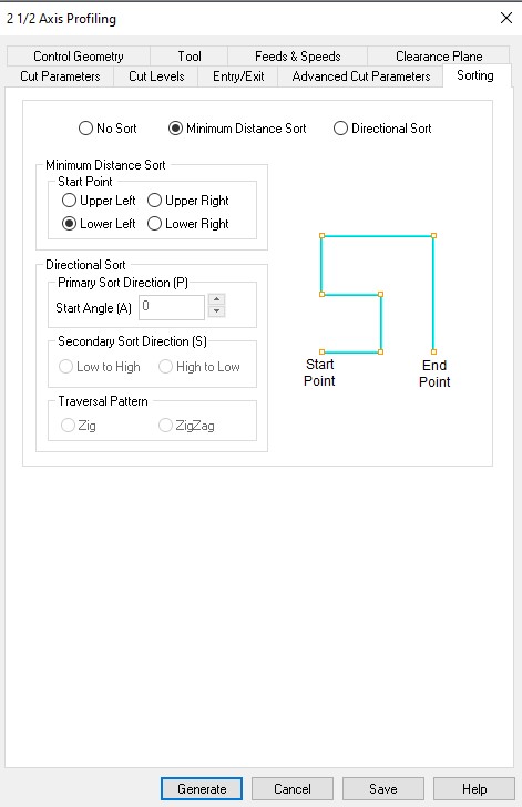 Advanced Cut Parameters and Sorting
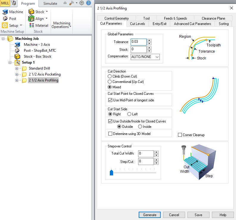 Clearence Path
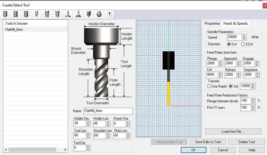 Tool Properties
 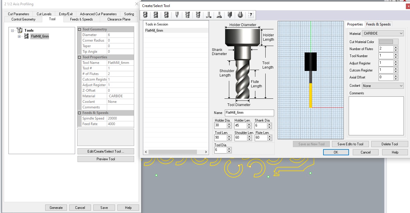 Tool Feeds & Spindles
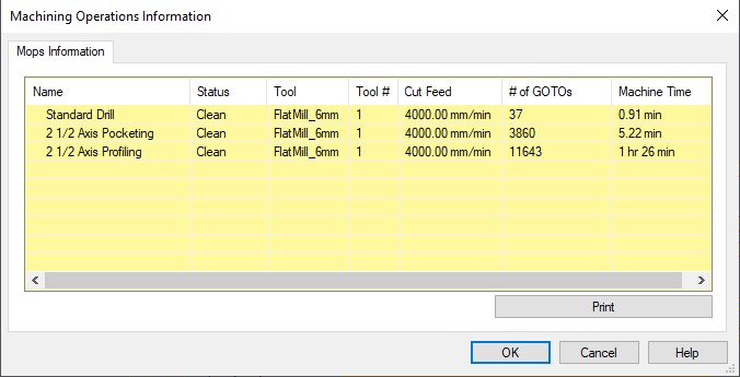
With these settings done we can export the file. We select the 3 folders in the setup and right click > Information.
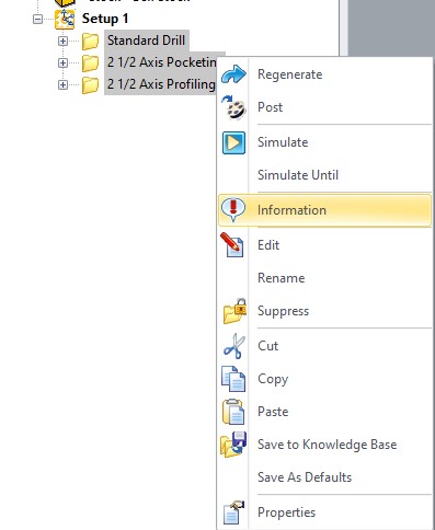
This will show up the Machine Operations Informations, that will give out an estimated Machine Time.
We take this file to the machine and place our material in the bed. We take the safety precautions.
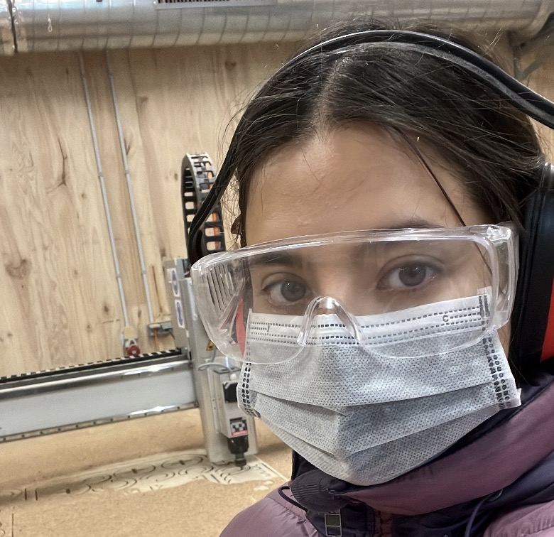
It's my birthday and I'm planning on enjoying it, so goggles on , tied hair and mask for the flying dust.
Machine is setup.
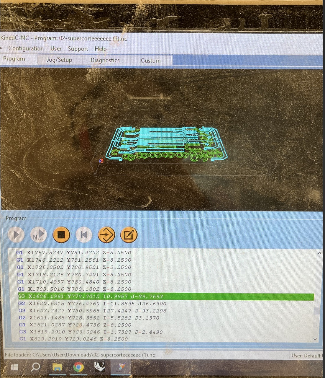
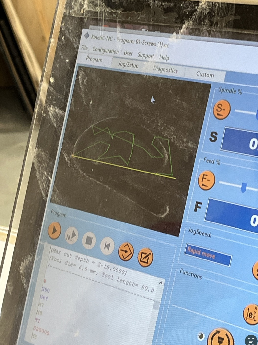
First up: drilling.
Fixed screws.
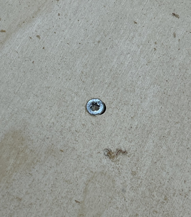
Many of them. With the board tightly placed on the bed. Let's pocket.
Voilà.
Now let's cut.
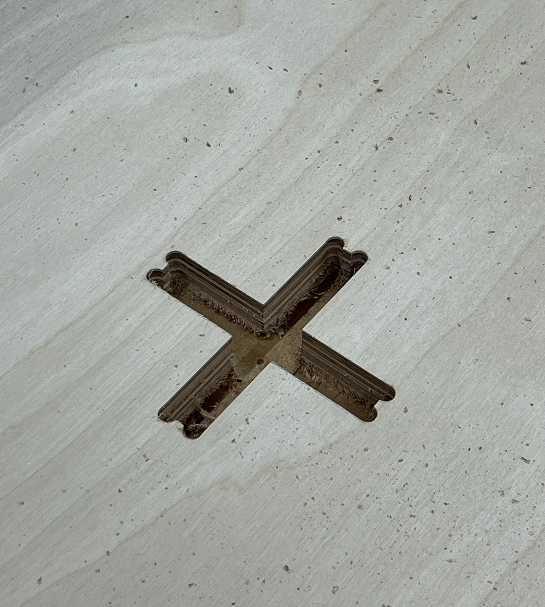
All done. Unfortunately, the downside of planning everything in 2D is that I couldn’t visualize the actual assembly. I didn’t think about how I would move the pieces into place—just focused on whether they fit, not how they’d get there. So the transverse parts of the castle couldn’t be positioned where I needed them. They would only work if they were somehow already there, like magic.
:/
It's ok, these things happen. I was able to make the columns work and the fittings where very precise.
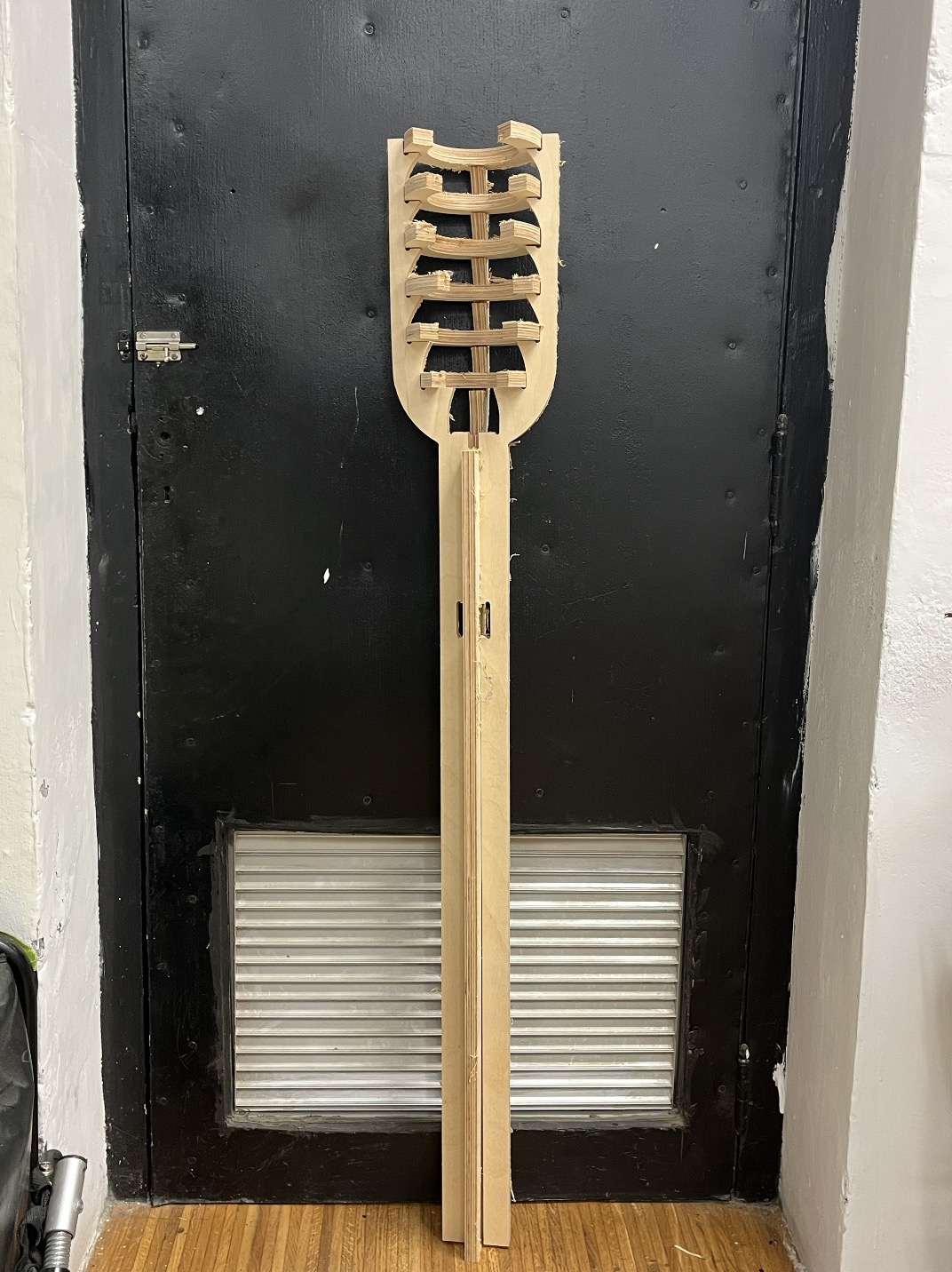
It's interesting that unlike laser cutting, CNC machining with plywood doesn’t require kerf compensation. It seems the wood expands slightly by a fraction of a millimeter after cutting. So I didn’t need to adjust any dimensions.
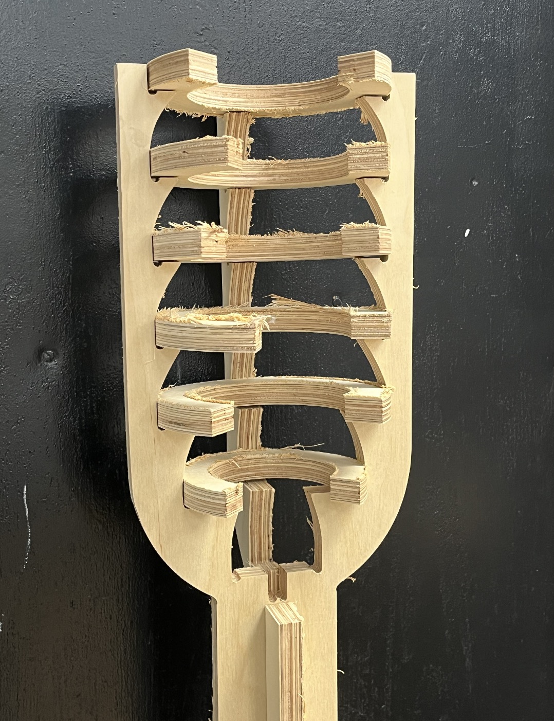
That's it for now, I'll try to continue this project later on since I was hoping to build a two-meter-long castle structure that would hold aluminum pieces in its transverse sections and function like a bar chime instrument.
Mabye soon. For the moment we'll just have to imagine it. ;)
You can access the design files here. And checkout our group assigment project for the week!