(not good one)Parametric Construction Kit
Write something at the front
I should learn my parametric design built before isn't the real one. I should learn how to make a parametric design with the 3D software before. I am using Onshape and watched the tutorial videos.

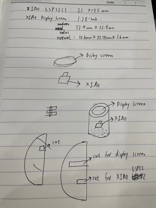
What I am going to build is a modular module, containing XIAO LCD Display(32.512mm) and XIAO ESP32S3 Sense board.
The result of mine
The steps
I first got the idea of patametric design from the tutorial video. So I first build the center of my module.
My idea module is a XIAO board connecting with a XIAO OLED screen display.
I will design the board meet the desgin requirements of two boards.
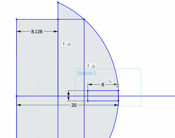
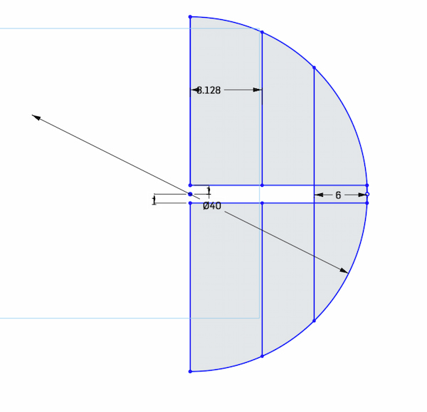
Build the center of the module
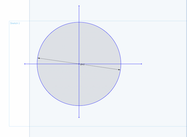
I first want to build the center of the module, this is the biggest circle of in the module. The middle one.
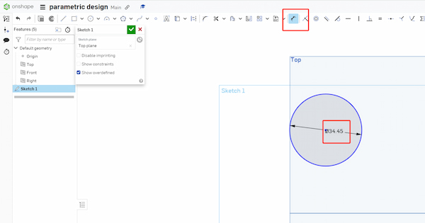
I set the radius as 20mm, which will be the largest radius of the module.
I then set 6mm of the snap to ensure the stability.
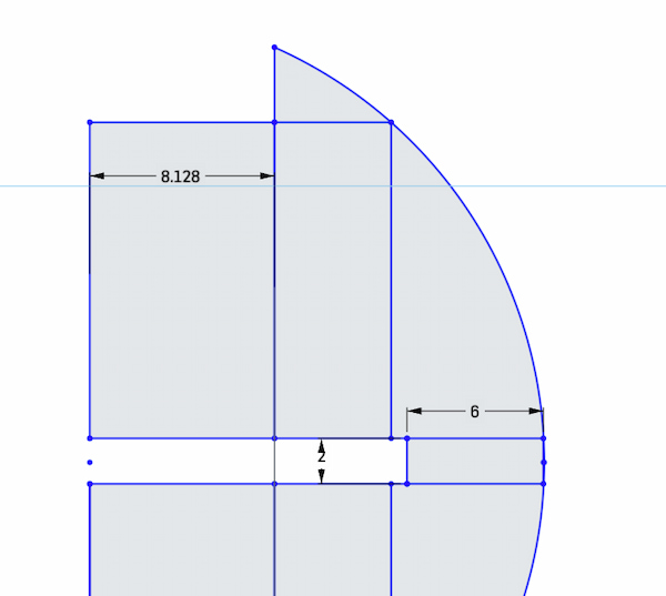
Then I set all directions with all same design:
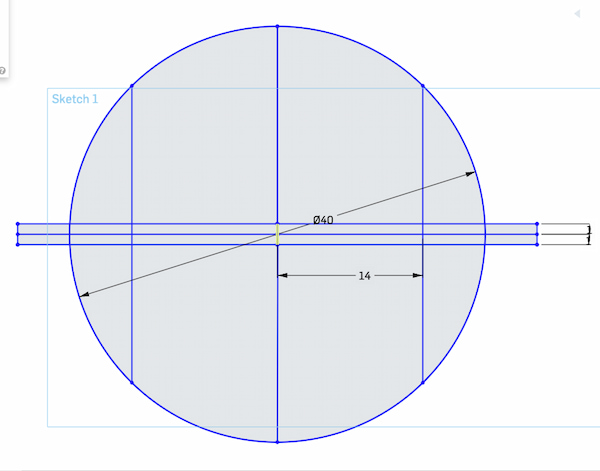
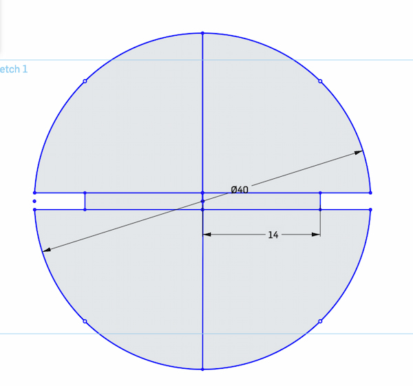
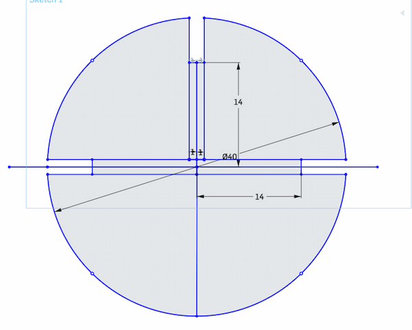
Finally, I have all four directions with same parameters.
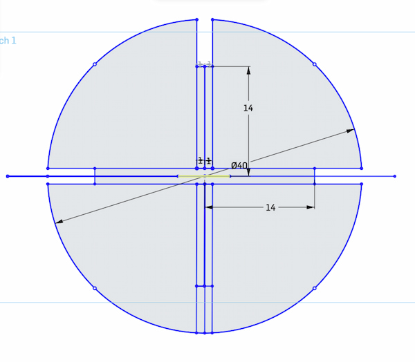
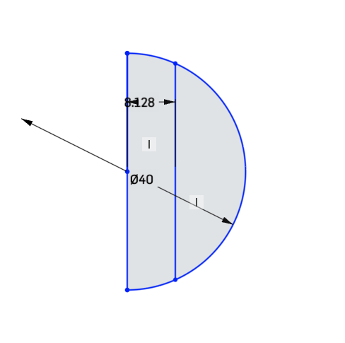
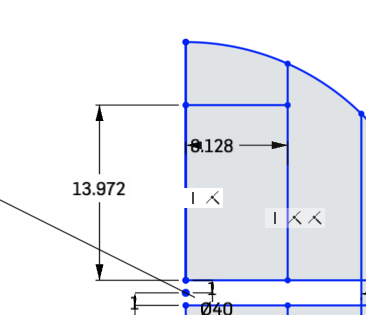
Oh I made a terrible mistake
I assume the display is square! I got the paramatic design wrong!
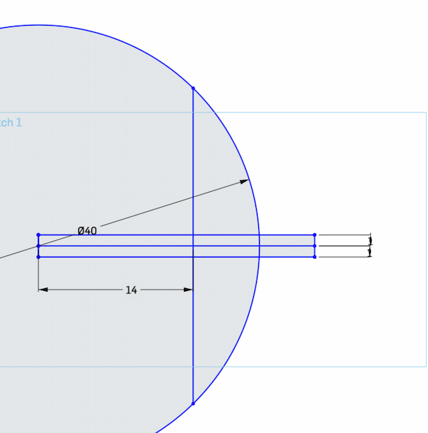
The display area shouldn't be 8.128 mm and should be 32.512 mm excatly!
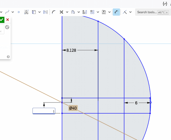
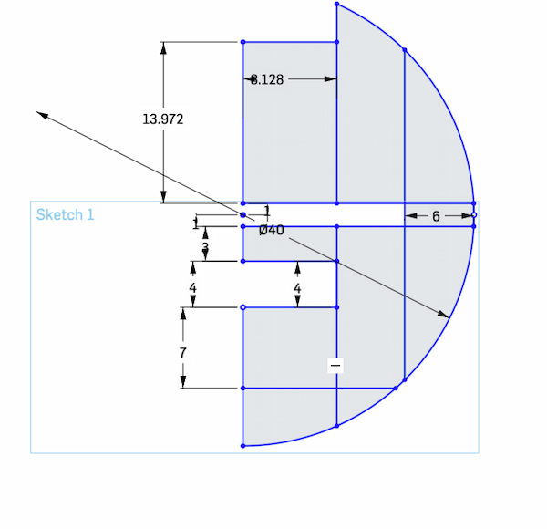
Assumeing I am putting a circluar module with 8.128 mm radius:
The snap should be met the requirment of the middle circle.
Stick to the 8.128mm radius deisn:
I got the radius wrong. Since it is the parametric design learning, I sticked to the 8.128mm radius:
And continue to do my project:
The middle part should be met the requirement to the largest board.
Fianlly I have one part of the module:
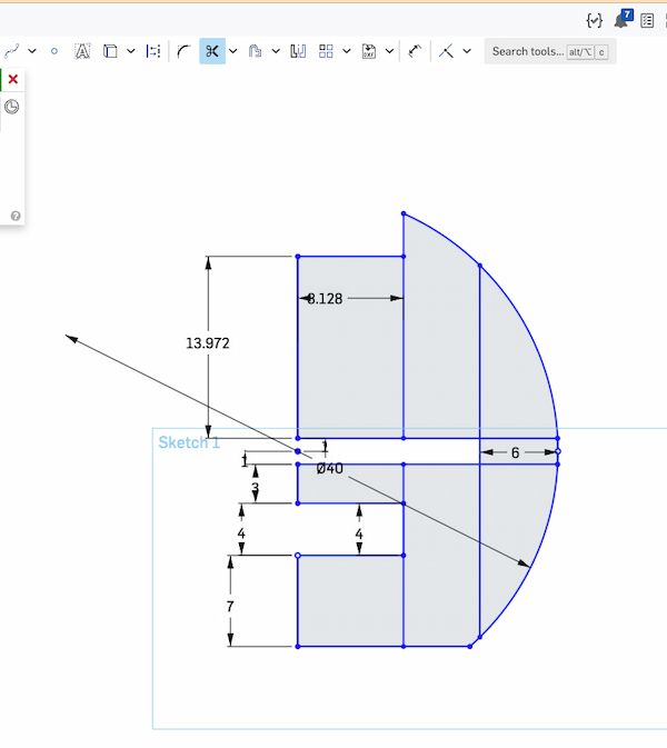
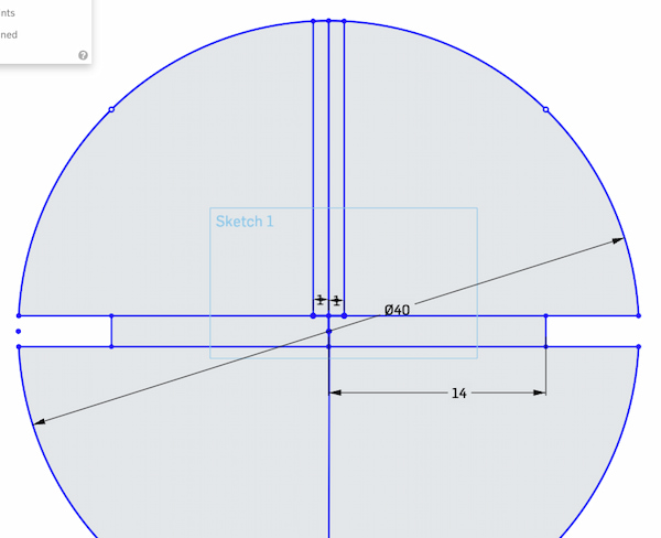
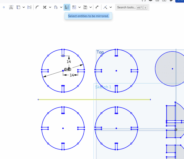
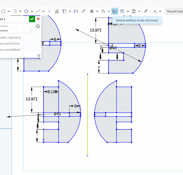
I thenk use a tool called mirror. I drop a line and click it, it will automatically generate one opposite.
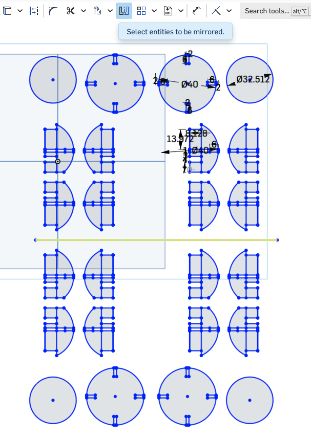
Final Result on the Onshape
This is what it looks like on the Onshape:
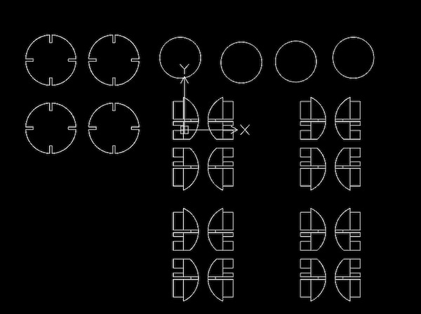
This is what it looks like with DXF on Onshape:
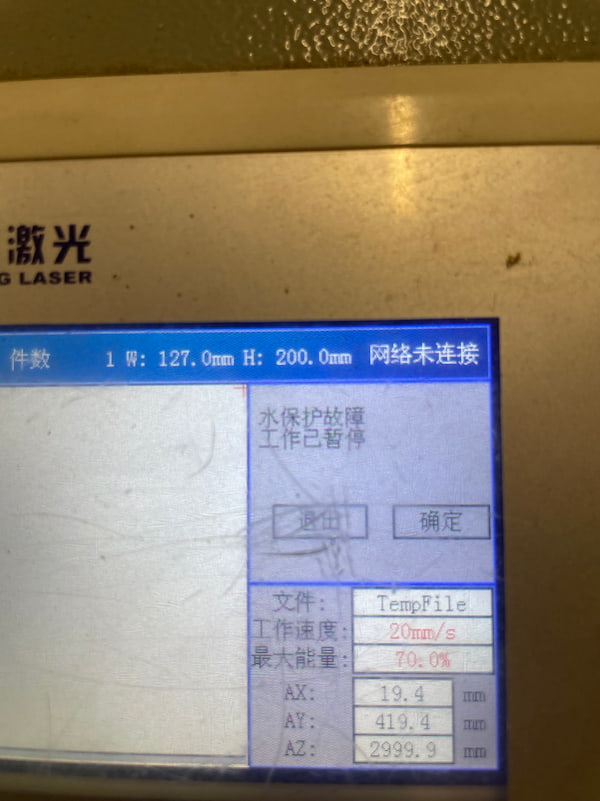
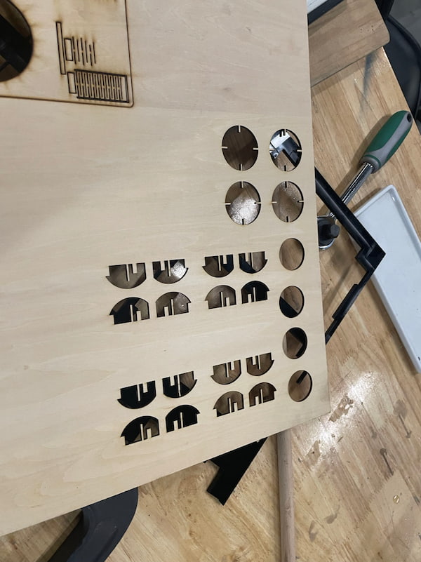
Cut the 2mm cardboard with Laser Cutting Machine
I upload the .dxf file into the file into the computer connecting the machine, since it all sets up(checking the group assignment), my job is only uploading the file and placing the board.
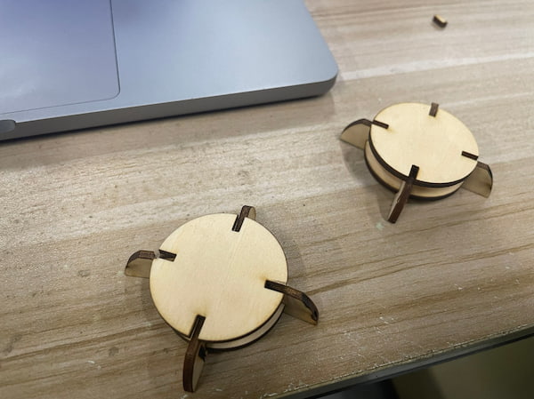
The board looks like this after the cutting:
And here are my parts:
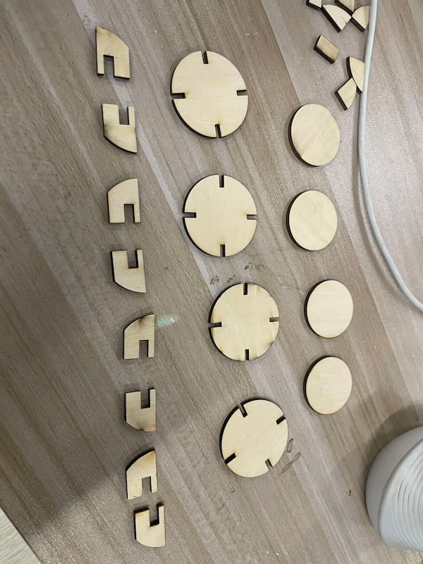
It is a little unexpected because I want to have one board holding a XIAO and one board holding a screen display. But the connecting is kind of OK: