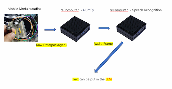
(input) Mobile Module - Raw Audio Data to Words
Updated on 6.10th, I have now working on the input parts, metioned by Neil, on the presentation day. I decided not using SD card to transmit the date and make more easy way - using Wi-Fi, which I have learnt quite OK.
The basic software idea:
From the knowledge from Week 12, I understood there are some issues about using I2S with MicroPython on XIAO ESP32C3. Thus my input progress has to be like this:
- XIAO ESP32C3 with INMP441 running Arduino, and sending audio data(audio frame) to under one IP address, like
192.168.66.123. - (optional)Another XIAO ESP32C3 with RGB running MicroPython, converting audio frame to a WAV file and then transmitting it to the reComputer through , flashing RGB when receiving.
- reCOmputer can do two options:
- Reading data from the fisrt one, and computing the audio frame and converting to words(text) and sending them to the LLM.
- Receiving file from the second one, and reading it as words and putting them in the LLM.
Software Part 1: Output audio raw data to audio frame
The audio data from week12 are all number(raw format) and need to be converted to the audio frame and have to be a suitable format.
And the specific format depends on the requirements of the speech recognition system I am using.
Here are common ones:
WAV(Waveform Audio File Format): A popular uncompressed audio format that stores audio data along with metadata.PCM(Pulse-Code Modulation): A raw audio format that represents the amplitude of the audio signal at each sample point.FLAC(Free Lossless Audio Codec): A lossless compressed audio format that reduces file size while preserving audio quality.
The ESP32C3 is not powerful enough to convert the data to the audio frame
What I can use this mobile module do is packing the raw data from the INMP441 and applying XIAO ESP32C3 to send them out, using Wi-Fi.
This is the code for packaging and printing on the serial port:
/*
  ESP32 I2S Microphone Sample
  esp32-i2s-mic-sample.ino
  Sample sound from I2S microphone, display on Serial Monitor
  Requires INMP441 I2S microphone

  DroneBot Workshop 2022
  https://dronebotworkshop.com
*/

// Include I2S driver
#include <driver/i2s.h>

// Connections to INMP441 I2S microphone
#define I2S_WS 9
#define I2S_SD 10
#define I2S_SCK 8

// Use I2S Processor 0
#define I2S_PORT I2S_NUM_0

// Define input buffer length
#define bufferLen 64
int16_t sBuffer[bufferLen];

void i2s_install() {
  // Set up I2S Processor configuration
  const i2s_config_t i2s_config = {
    .mode = i2s_mode_t(I2S_MODE_MASTER | I2S_MODE_RX),
    .sample_rate = 44100,
    .bits_per_sample = i2s_bits_per_sample_t(16),
    .channel_format = I2S_CHANNEL_FMT_ONLY_LEFT,
    .communication_format = i2s_comm_format_t(I2S_COMM_FORMAT_STAND_I2S),
    .intr_alloc_flags = 0,
    .dma_buf_count = 8,
    .dma_buf_len = bufferLen,
    .use_apll = false
  };

  i2s_driver_install(I2S_PORT, &i2s_config, 0, NULL);
}

void i2s_setpin() {
  // Set I2S pin configuration
  const i2s_pin_config_t pin_config = {
    .bck_io_num = I2S_SCK,
    .ws_io_num = I2S_WS,
    .data_out_num = -1,
    .data_in_num = I2S_SD
  };

  i2s_set_pin(I2S_PORT, &pin_config);
}

void setup() {

  // Set up Serial Monitor
  Serial.begin(115200);
  Serial.println("ESP32 I2S Microphone Test");

  delay(1000);

  // Set up I2S
  i2s_install();
  i2s_setpin();
  i2s_start(I2S_PORT);

  delay(500);
}

void loop() {
  // Get I2S data and place in data buffer
  size_t bytesIn = 0;
  esp_err_t result = i2s_read(I2S_PORT, &sBuffer, bufferLen, &bytesIn, portMAX_DELAY);

  if (result == ESP_OK) {
    // Read I2S data buffer
    int16_t samples_read = bytesIn / 8;
    if (samples_read > 0) {
      // Print audio frame data to Serial Monitor
      Serial.print("Audio Frame: ");
      for (int16_t i = 0; i < samples_read; ++i) {
        Serial.print(sBuffer[i]);
        Serial.print(" ");
      }
      Serial.println();
    }
  }
}
There is the output:
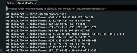
Software Part 2: Audio data(packagde) streaming from mobile module to reComputer
I am using Wi-Fi to apply this function. These parts should be under the same network and here is one reference for connecting XIAO ESP32C3 to Wi-Fi and one reference from above.
Some parameters changable:
bufferLen: Buffer to store audio data read from the microphone, here is 64.sample rate44100 Hz, which is the default value in pyaudio.bits per sample16, which corresponds to the paInt16 format in pyaudio.
Conecting Wi-Fi and Sending data to its IP
For integrating these two reference, I do some changes about the code(powered by GPT of course):
-
The connection is still the same:
#define I2S_WS 9
#define I2S_SD 10
#define I2S_SCK 8 -
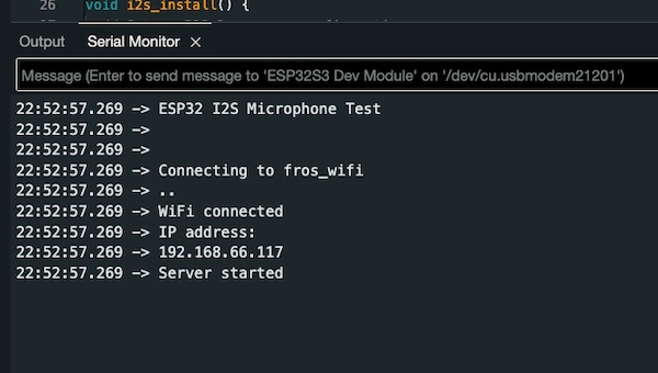
After successfully connecting to Wi-Fi, the IP address of the ESP32C3 MCU board is printed using:
Serial.println(WiFi.localIP()); -
A
WiFiServerobject namedserveris created, specifying the port number (12345in this example) on which the server will listen for incoming connections. -
In the
setup()function, the server is started using:server.begin();And a message is printed to indicate that the server has started.
-
In the
loop()function, the code checks if a client has connected using:server.available();If a client is connected, it prints a message indicating that a client has connected.
-
The I2S audio data is read and stored in the
sBufferas before. -
If audio samples are successfully read, they are sent to the connected client using:
client.write((uint8_t*)sBuffer, bytesIn); -
After sending the data, the client connection is closed using:
client.stop();And a message is printed to indicate that the client has disconnected.
The full code:
#include <WiFi.h>
#include <driver/i2s.h>

const char* ssid     = "fros_wifi";
const char* password = "66668888";

// Connections to INMP441 I2S microphone
#define I2S_WS 9
#define I2S_SD 10
#define I2S_SCK 8

// Use I2S Processor 0
#define I2S_PORT I2S_NUM_0

// Define input buffer length
#define bufferLen 64
int16_t sBuffer[bufferLen];

// Server configuration
WiFiServer server(12345);

void i2s_install() {
  // Set up I2S Processor configuration
  const i2s_config_t i2s_config = {
    .mode = i2s_mode_t(I2S_MODE_MASTER | I2S_MODE_RX),
    .sample_rate = 44100,
    .bits_per_sample = i2s_bits_per_sample_t(16),
    .channel_format = I2S_CHANNEL_FMT_ONLY_LEFT,
    .communication_format = i2s_comm_format_t(I2S_COMM_FORMAT_STAND_I2S),
    .intr_alloc_flags = 0,
    .dma_buf_count = 8,
    .dma_buf_len = bufferLen,
    .use_apll = false
  };

  i2s_driver_install(I2S_PORT, &i2s_config, 0, NULL);
}

void i2s_setpin() {
  // Set I2S pin configuration
  const i2s_pin_config_t pin_config = {
    .bck_io_num = I2S_SCK,
    .ws_io_num = I2S_WS,
    .data_out_num = -1,
    .data_in_num = I2S_SD
  };

  i2s_set_pin(I2S_PORT, &pin_config);
}

void setup() {
  // Set up Serial Monitor
  Serial.begin(115200);
  Serial.println("ESP32 I2S Microphone Test");

  delay(1000);

  // Set up I2S
  i2s_install();
  i2s_setpin();
  i2s_start(I2S_PORT);

  delay(500);

  // Connect to Wi-Fi
  Serial.println();
  Serial.println();
  Serial.print("Connecting to ");
  Serial.println(ssid);

  WiFi.begin(ssid, password);

  while (WiFi.status() != WL_CONNECTED) {
    delay(500);
    Serial.print(".");
  }

  Serial.println("");
  Serial.println("WiFi connected");

  // Print the IP address of the ESP32C3 MCU board
  Serial.println("IP address: ");
  Serial.println(WiFi.localIP());

  // Start the server
  server.begin();
  Serial.println("Server started");
}

void loop() {
  // Check if a client has connected
  WiFiClient client = server.available();
  if (client) {
    Serial.println("Client connected");

    // Get I2S data and place in data buffer
    size_t bytesIn = 0;
    esp_err_t result = i2s_read(I2S_PORT, &sBuffer, bufferLen, &bytesIn, portMAX_DELAY);

    if (result == ESP_OK) {
      // Read I2S data buffer
      int16_t samples_read = bytesIn / 8;
      if (samples_read > 0) {
        // Send the audio data to the connected client
        client.write((uint8_t*)sBuffer, bytesIn);
      }
    }

    // Close the connection
    client.stop();
    Serial.println("Client disconnected");
  }
}
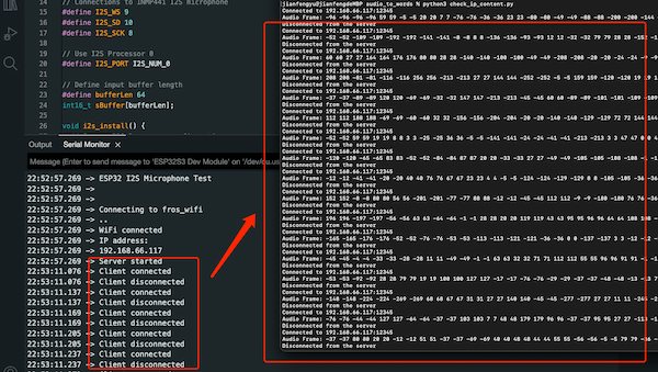
Connecting and checking its IP:
Reading the data from its IP
Now I need to write a script to read the data from 192.168.66.117, continuously.
- I create a new server socket and establish a connection to the ESP32C3 MCU board using server_socket.connect((SERVER_IP, SERVER_PORT)), which is
192.168.66.117, and12345. - Once connected, the script enters an inner while True loop where it continuously receives data from the ESP32C3 MCU board using server_socket.recv(1024).
- The received data is printed as hexadecimal values using data.hex().
It is powered by GPT and it helps me consider all the conditions.
Here is the full code:
import socket

# Set up the server socket
SERVER_IP = '192.168.66.117'  # IP address of the ESP32C3 MCU board
SERVER_PORT = 12345  # Choose a port number

while True:
    try:
        server_socket = socket.socket(socket.AF_INET, socket.SOCK_STREAM)
        server_socket.connect((SERVER_IP, SERVER_PORT))
        print(f"Connected to {SERVER_IP}:{SERVER_PORT}")

        while True:
            # Receive data from the ESP32C3 MCU board
            data = server_socket.recv(1024)
            if not data:
                break

            # Process the received data
            # Here, we print the raw data as hexadecimal values
            print("Received data:", data.hex())

        # Close the server socket
        server_socket.close()
        print("Disconnected from the server")

    except ConnectionRefusedError:
        print("Connection refused. Retrying...")
    except ConnectionResetError:
        print("Connection reset. Retrying...")
    except KeyboardInterrupt:
        print("Keyboard interrupt received. Exiting...")
        break

    # Wait for a short interval before retrying
    socket.timeout(1)
and the output formate like(customized frame):
import socket

# Set up the server socket
SERVER_IP = '192.168.66.117'  # IP address of the ESP32C3 MCU board
SERVER_PORT = 12345  # Choose a port number

while True:
    try:
        server_socket = socket.socket(socket.AF_INET, socket.SOCK_STREAM)
        server_socket.connect((SERVER_IP, SERVER_PORT))
        print(f"Connected to {SERVER_IP}:{SERVER_PORT}")

        while True:
            # Receive data from the ESP32C3 MCU board
            data = server_socket.recv(1024)
            if not data:
                break

            # Process the received data
            samples_read = len(data) // 2  # Each sample is 2 bytes (16-bit)
            audio_frame = [int.from_bytes(data[i:i+2], byteorder='little', signed=True) for i in range(0, len(data), 2)]

            # Print audio frame data
            print("Audio Frame:", end=" ")
            for sample in audio_frame:
                print(sample, end=" ")
            print()

        # Close the server socket
        server_socket.close()
        print("Disconnected from the server")

    except ConnectionRefusedError:
        print("Connection refused. Retrying...")
    except ConnectionResetError:
        print("Connection reset. Retrying...")
    except KeyboardInterrupt:
        print("Keyboard interrupt received. Exiting...")
        break

    # Wait for a short interval before retrying
    socket.timeout(1)
The final output is:
(Updated)Converting audio raw data into WAV file
Update on 7.6th, I have known that Sending raw audio data to my reComputer server is less efficient. Reference by a tutorial on YouTube, I think converting the recording my audio into a recording file on the ESP device and send the recording file over Wi-Fi is more likely workable.
For recording the raw audio data and converting them into WAV file:
#include <driver/i2s.h>
#include <SPIFFS.h>

#define I2S_WS 9
#define I2S_SD 20
#define I2S_SCK 8
#define I2S_PORT I2S_NUM_0
#define I2S_SAMPLE_RATE   (16000)
#define I2S_SAMPLE_BITS   (16)
#define I2S_READ_LEN      (16 * 1024)
#define RECORD_TIME       (20) //Seconds
#define I2S_CHANNEL_NUM   (1)
#define FLASH_RECORD_SIZE (I2S_CHANNEL_NUM * I2S_SAMPLE_RATE * I2S_SAMPLE_BITS / 8 * RECORD_TIME)

File file;
const char filename[] = "/recording.wav";
const int headerSize = 44;

void setup() {
  // put your setup code here, to run once:
  Serial.begin(115200);
  SPIFFSInit();
  i2sInit();
  xTaskCreate(i2s_adc, "i2s_adc", 1024 * 2, NULL, 1, NULL);
}

void loop() {
  // put your main code here, to run repeatedly:

}

void SPIFFSInit(){
  if(!SPIFFS.begin(true)){
    Serial.println("SPIFFS initialisation failed!");
    while(1) yield();
  }

  SPIFFS.remove(filename);
  file = SPIFFS.open(filename, FILE_WRITE);
  if(!file){
    Serial.println("File is not available!");
  }

  byte header[headerSize];
  wavHeader(header, FLASH_RECORD_SIZE);

  file.write(header, headerSize);
  listSPIFFS();
}

void i2sInit(){
  i2s_config_t i2s_config = {
    .mode = (i2s_mode_t)(I2S_MODE_MASTER | I2S_MODE_RX),
    .sample_rate = I2S_SAMPLE_RATE,
    .bits_per_sample = i2s_bits_per_sample_t(I2S_SAMPLE_BITS),
    .channel_format = I2S_CHANNEL_FMT_ONLY_LEFT,
    .communication_format = i2s_comm_format_t(I2S_COMM_FORMAT_I2S | I2S_COMM_FORMAT_I2S_MSB),
    .intr_alloc_flags = 0,
    .dma_buf_count = 64,
    .dma_buf_len = 1024,
    .use_apll = 1
  };

  i2s_driver_install(I2S_PORT, &i2s_config, 0, NULL);

  const i2s_pin_config_t pin_config = {
    .bck_io_num = I2S_SCK,
    .ws_io_num = I2S_WS,
    .data_out_num = -1,
    .data_in_num = I2S_SD
  };

  i2s_set_pin(I2S_PORT, &pin_config);
}


void i2s_adc_data_scale(uint8_t * d_buff, uint8_t* s_buff, uint32_t len)
{
    uint32_t j = 0;
    uint32_t dac_value = 0;
    for (int i = 0; i < len; i += 2) {
        dac_value = ((((uint16_t) (s_buff[i + 1] & 0xf) << 8) | ((s_buff[i + 0]))));
        d_buff[j++] = 0;
        d_buff[j++] = dac_value * 256 / 2048;
    }
}

void i2s_adc(void *arg)
{

    int i2s_read_len = I2S_READ_LEN;
    int flash_wr_size = 0;
    size_t bytes_read;

    char* i2s_read_buff = (char*) calloc(i2s_read_len, sizeof(char));
    uint8_t* flash_write_buff = (uint8_t*) calloc(i2s_read_len, sizeof(char));

    i2s_read(I2S_PORT, (void*) i2s_read_buff, i2s_read_len, &bytes_read, portMAX_DELAY);
    i2s_read(I2S_PORT, (void*) i2s_read_buff, i2s_read_len, &bytes_read, portMAX_DELAY);

    Serial.println(" *** Recording Start *** ");
    while (flash_wr_size < FLASH_RECORD_SIZE) {
        //read data from I2S bus, in this case, from ADC.
        i2s_read(I2S_PORT, (void*) i2s_read_buff, i2s_read_len, &bytes_read, portMAX_DELAY);
        //example_disp_buf((uint8_t*) i2s_read_buff, 64);
        //save original data from I2S(ADC) into flash.
        i2s_adc_data_scale(flash_write_buff, (uint8_t*)i2s_read_buff, i2s_read_len);
        file.write((const byte*) flash_write_buff, i2s_read_len);
        flash_wr_size += i2s_read_len;
        ets_printf("Sound recording %u%%\n", flash_wr_size * 100 / FLASH_RECORD_SIZE);
        ets_printf("Never Used Stack Size: %u\n", uxTaskGetStackHighWaterMark(NULL));
    }
    file.close();

    free(i2s_read_buff);
    i2s_read_buff = NULL;
    free(flash_write_buff);
    flash_write_buff = NULL;

    listSPIFFS();
    vTaskDelete(NULL);
}

void example_disp_buf(uint8_t* buf, int length)
{
    printf("======\n");
    for (int i = 0; i < length; i++) {
        printf("%02x ", buf[i]);
        if ((i + 1) % 8 == 0) {
            printf("\n");
        }
    }
    printf("======\n");
}

void wavHeader(byte* header, int wavSize){
  header[0] = 'R';
  header[1] = 'I';
  header[2] = 'F';
  header[3] = 'F';
  unsigned int fileSize = wavSize + headerSize - 8;
  header[4] = (byte)(fileSize & 0xFF);
  header[5] = (byte)((fileSize >> 8) & 0xFF);
  header[6] = (byte)((fileSize >> 16) & 0xFF);
  header[7] = (byte)((fileSize >> 24) & 0xFF);
  header[8] = 'W';
  header[9] = 'A';
  header[10] = 'V';
  header[11] = 'E';
  header[12] = 'f';
  header[13] = 'm';
  header[14] = 't';
  header[15] = ' ';
  header[16] = 0x10;
  header[17] = 0x00;
  header[18] = 0x00;
  header[19] = 0x00;
  header[20] = 0x01;
  header[21] = 0x00;
  header[22] = 0x01;
  header[23] = 0x00;
  header[24] = 0x80;
  header[25] = 0x3E;
  header[26] = 0x00;
  header[27] = 0x00;
  header[28] = 0x00;
  header[29] = 0x7D;
  header[30] = 0x00;
  header[31] = 0x00;
  header[32] = 0x02;
  header[33] = 0x00;
  header[34] = 0x10;
  header[35] = 0x00;
  header[36] = 'd';
  header[37] = 'a';
  header[38] = 't';
  header[39] = 'a';
  header[40] = (byte)(wavSize & 0xFF);
  header[41] = (byte)((wavSize >> 8) & 0xFF);
  header[42] = (byte)((wavSize >> 16) & 0xFF);
  header[43] = (byte)((wavSize >> 24) & 0xFF);

}


void listSPIFFS(void) {
  Serial.println(F("\r\nListing SPIFFS files:"));
  static const char line[] PROGMEM =  "=================================================";

  Serial.println(FPSTR(line));
  Serial.println(F("  File name                              Size"));
  Serial.println(FPSTR(line));

  fs::File root = SPIFFS.open("/");
  if (!root) {
    Serial.println(F("Failed to open directory"));
    return;
  }
  if (!root.isDirectory()) {
    Serial.println(F("Not a directory"));
    return;
  }

  fs::File file = root.openNextFile();
  while (file) {

    if (file.isDirectory()) {
      Serial.print("DIR : ");
      String fileName = file.name();
      Serial.print(fileName);
    } else {
      String fileName = file.name();
      Serial.print("  " + fileName);
      // File path can be 31 characters maximum in SPIFFS
      int spaces = 33 - fileName.length(); // Tabulate nicely
      if (spaces < 1) spaces = 1;
      while (spaces--) Serial.print(" ");
      String fileSize = (String) file.size();
      spaces = 10 - fileSize.length(); // Tabulate nicely
      if (spaces < 1) spaces = 1;
      while (spaces--) Serial.print(" ");
      Serial.println(fileSize + " bytes");
    }

    file = root.openNextFile();
  }

  Serial.println(FPSTR(line));
  Serial.println();
  delay(1000);
}
Starting:
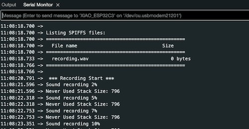
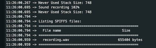
and Done:
And then I can use this example code, for uploading the recorded file in SPIFFS to a server, under my local network:
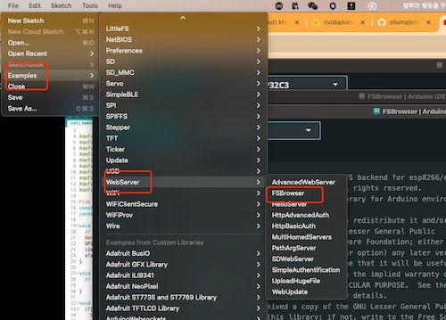
But it requires two times uploading, this is one time reference: example.
Some information that should be awared of:
- The wifi ssid and password should be written right
  char* ssid = "<YOUR_WIFI_SSID>";
  char* password = "<YOUR_WIFI_PW>";
- The connection ports
#define I2S_WS 9
#define I2S_SD 20
#define I2S_SCK 8
- The ip address from the rerouter:
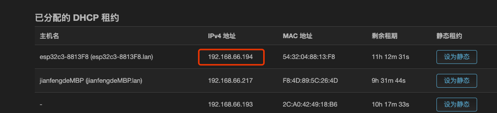
Finally, going to the corresponding IP address, and type the name of the file, like:
http://192.168.66.194/matthew_recording.wav
Will download the recording file.

Software Part 3: WAV file to text on reComputer
This part can be achieved by some methods:
- Using google cloud speech(
python 3.11required).
pip install requests
pip install --upgrade google-cloud-speech
-
NVIDIA Riva - Since my reComputer is based on Jetson.
-
Canary based on NVIDIA NeMo - Publishing on huggingface.
The No.3 is looking fun.
Using this function will convert my WAV file into words:
import nemo.collections.asr as nemo_asr
asr_model = nemo_asr.models.ASRModel.from_pretrained("nvidia/canary-1b")

transcriptions = asr_model.transcribe(["file.wav"])
This is the model installation.
What I want to achieve is that it can automatically read my WAV file from the server and convert it and then input the words to my LLM. Hence, for integrating reading WAV file and convert it into words.
To achieve it, I will have multiple tasks:
- Create a script on the reComputer that can monitor the WAV file on the remote server (192.168.66.164)
- Check for updates, and download the file if updated,
- Then transcribe it using
canary-1b, - Finally submit the transcription to the React web page via Ollama API.
checking if updated:
#!/bin/bash

# Remote server details
REMOTE_IP="192.168.66.164"
REMOTE_PATH="http://192.168.66.164/matthew_recording.wav"
LOCAL_PATH="/download/matthew_recording.wav"

# Function to check for updates and download
sync_file() {
    rsync -az --checksum "$REMOTE_IP":"$REMOTE_PATH" "$LOCAL_PATH"
}

# Loop to keep checking every minute
while true; do
    sync_file
    sleep 60  # Check every 60 seconds
done
Putting downloaded file to the "canary-1b":
import os
import time
import hashlib
import nemo.collections.asr as nemo_asr

# NVIDIA NeMo model setup
asr_model = nemo_asr.models.ASRModel.from_pretrained("nvidia/canary-1b")

# File to watch
file_path = "./downlaod/matthew_recording.wav"
last_hash = None

while True:
    # Check for file updates by comparing hashes
    with open(file_path, "rb") as f:
        current_hash = hashlib.md5(f.read()).hexdigest()

    if current_hash != last_hash:
        # File has changed, perform transcription
        transcriptions = asr_model.transcribe([file_path])
        print("Transcribed text:", transcriptions[0])  # For debugging

        # TODO: send this transcription to the web server
        last_hash = currenthash

    time.sleep(60)  # Check every 60 seconds
Web side generating:
import requests

def send_transcription(text):
    url = 'http://localhost:11434/api/chat'
    data = {
        'model': 'llama3',
        'messages': [{'role': 'user', 'content': text}],
        'stream': True
    }
    response = requests.post(url, json=data)
    print(response.text)  # For debugging

# Place this inside the if condition where transcription is done
send_transcription(transcriptions[0])
Done
Previous
Updated on 6.1st, since it is kind of out of time. Still busy lately... I am just presenting the module how is normal used.
There are several wikis I can refer to later:
Main board Design
pressing the button and starting voice recognisation, the RGB light shows the microphone working, and when the board detects it, the board will "data transfer" to another MCU board
I want to ensure when I push the button there will be display feedback, and orgini
Voice Recognization
These two wiki can be refer to: