(Output) Mobile Module - Display and Relay Case design
Write something at the front
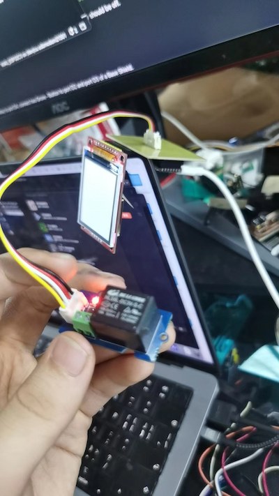
Updated on 7.7th, I want to design a case holding my pcb board, along with my display and my relay. Becasue my final idea is that I want my XIAO ESP32C3 can receive the message from my reComputer, and be able to do something(in this case, controlling thg relay).
Files Sharing
Here is the Onshape link for my output design.
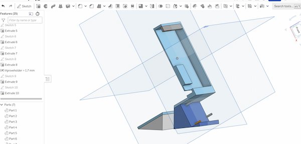
Design and test at the same time
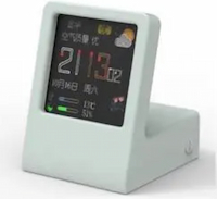
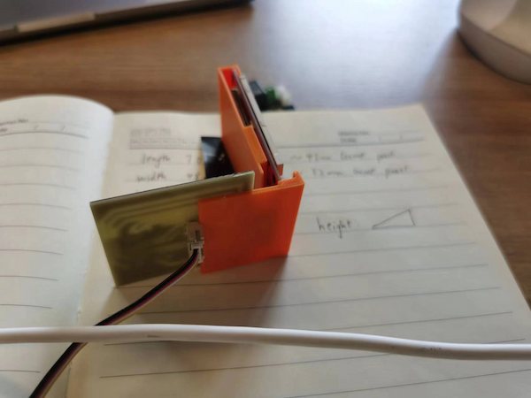
My idea for output design is simple, which might look like this:
But on my module there are multiple parameters that need to be measured:
My plan is while designing I printing for the test.
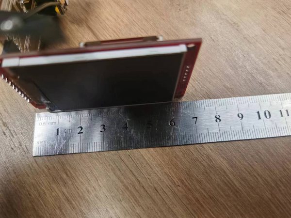
For the starters, calculating the length and the width:
Design half empty simple merge case first:
Not looking good for the first time:
But I do have the parameters and after fixing it, I can continue to make it better, like presenting the display only and calculating the length for the Grove connector. Later it occurs some good shape.
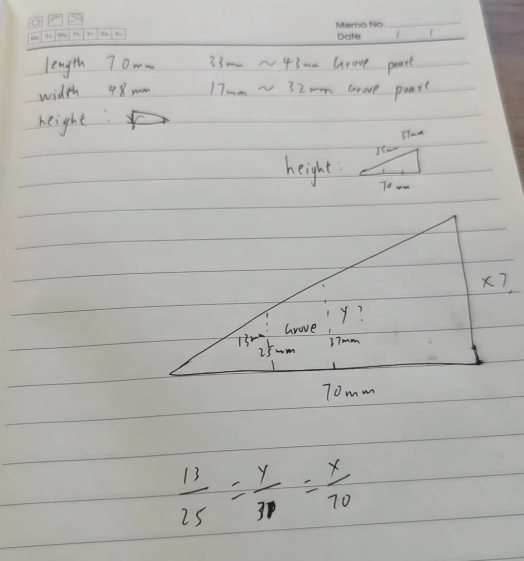
For making it better, I need to do some calculation - Because I'm going to design a bevel.
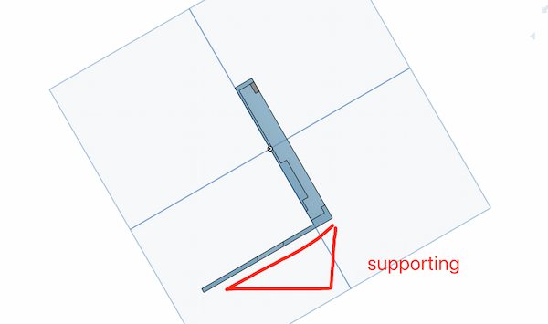
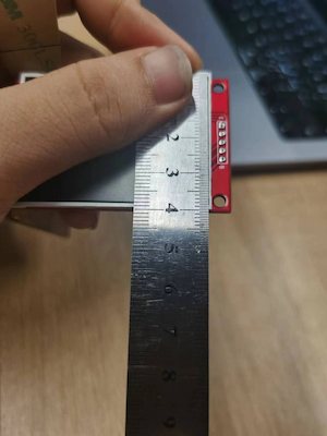
At the bottom, I need to consider the length of the grove conneector.
Then, I finish my calculation. This is simple Pythagorean theorem.
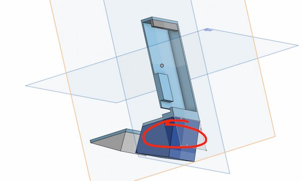
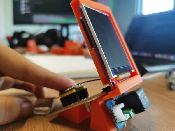
Much better now, but I need a space for my Grove - relay.
Luckiy I have the space:
For every grove, there actually some standard size round holes can be designed and fixed for user convenience. Mine is Grove 20X40 SMD Vertical and here is the reference page in Seeed Studio. But I should look out other sizes as well.
Designing the holes, watching for anything that might cause the unfit.

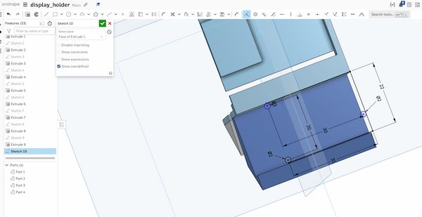
It is looking fine on the Onshape:
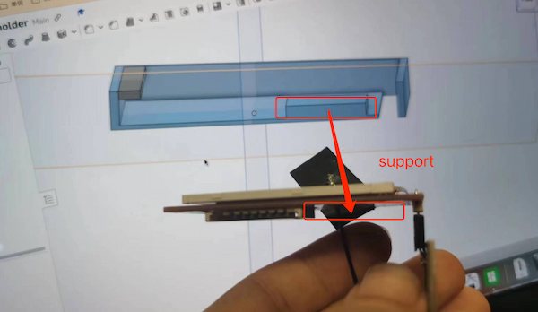
Testing out with the printer. I am using 0.4 nozzle and apply the support:

It may not be that elaborate and one of the small posts was wrong:
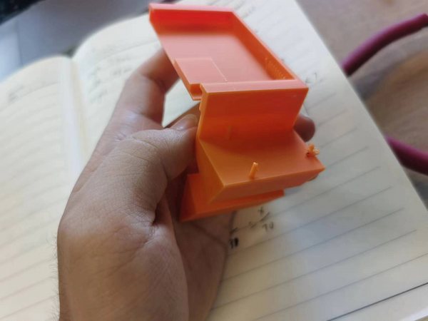
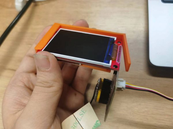
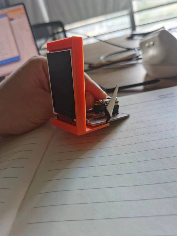
Eventually, it looks fine:
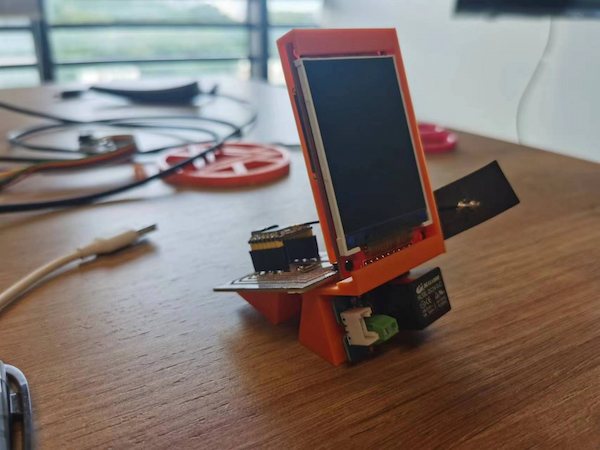
And now the only required thing is the Grove connector.
This case will be integrated into the whole case of the bot.