Week 17 - System Integration
Here are my week 17 assignment
System Integration and Packaging:
The whole system basic idea:
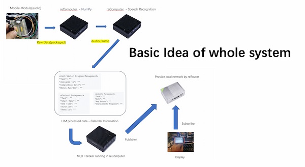
- Main computing device: reComputer, offering MQTT broker, AI computing, Running LLM and Browser Website.
- Networking device(I want to ensure all thing is local): reRouter, offering Wi-Fi wireless connection and wire connection.
- One mobile module with INMP441 is inputting voice
- One mobile module with ILI9341 is display the processed information.
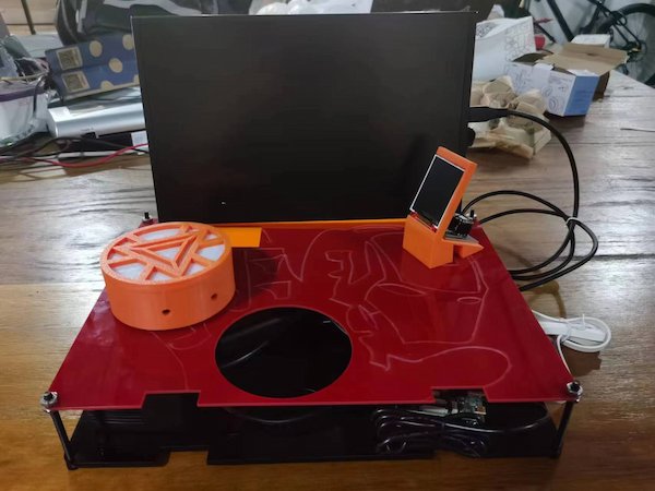
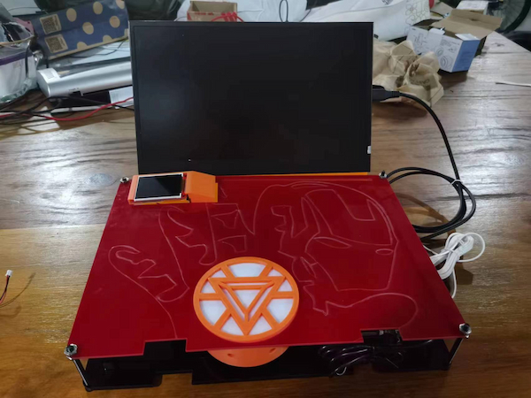
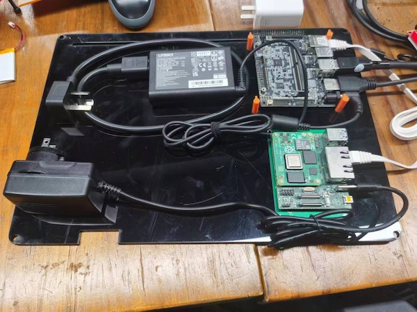
The whole system carraging:
The packaging is big, even though I remove the original cases of computing devices. It is still big, no mention the power adapter. But this can be carried:
This will be the monitor attached one:
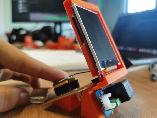
The mobile module:
Fabrication Processes:
Updated on 7.8th, I have updated my project, with both input and output. Thus, my design are changing here:
The case for input module:
Top cover(3D printing):
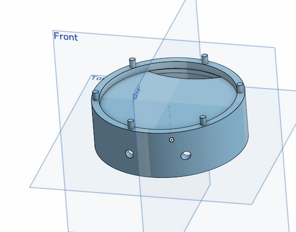
Middle part(3D printing):
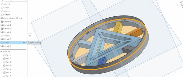
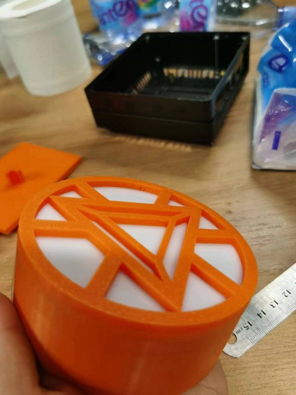
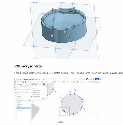
And the RGB light cover(2D design):
Eventually:
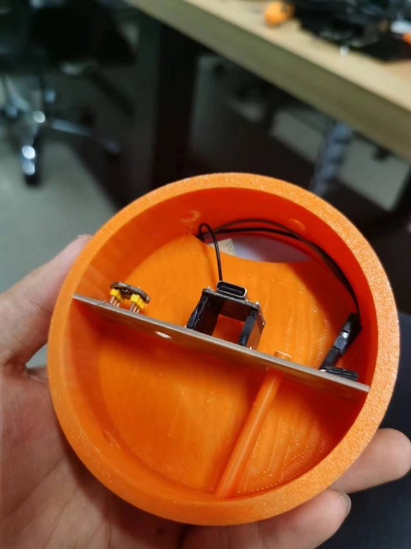
Extend the rgb lights out, along with XIAO antenna:
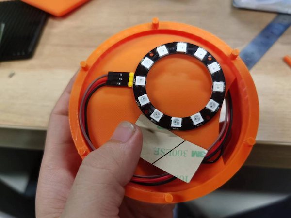
Finally put the acrylic plate init can cover it up:
The case for output module:
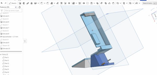
Display holder and Grove Relay holder(3D printing):
Eventually, it looks fine:
The system case design - 2D laser cutting
This part is to make the work look good, tidy and logical.
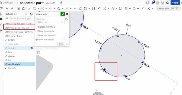
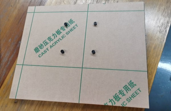
- The RGB display is best with a filter layer. So cut some acrylic sheets against the blueprints:
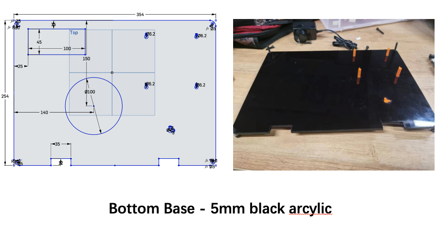
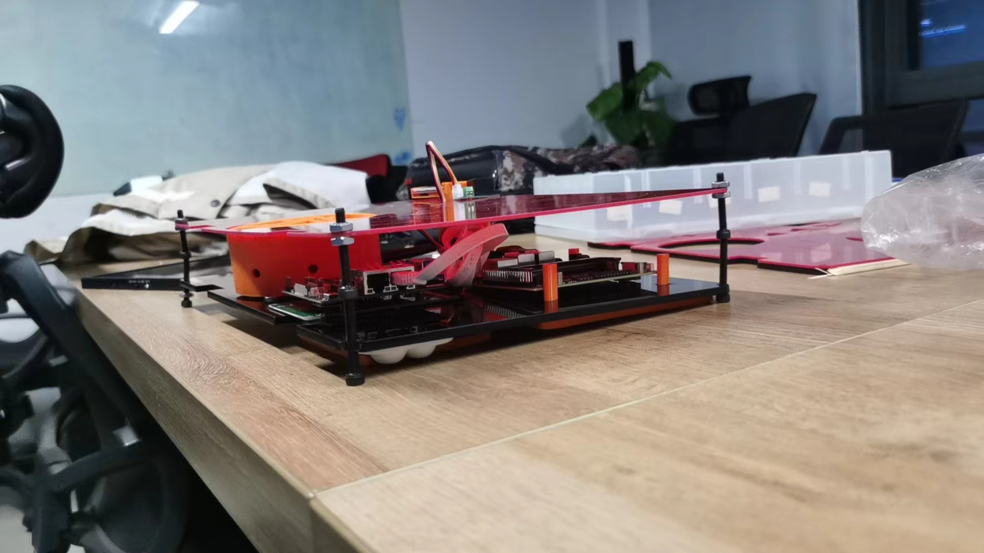
- Since I used some big equipments/devices (reComputer and reRouter), I'm going to have two large acrylic sheets to hold everything together:
Thus the laser cutting is necessary:
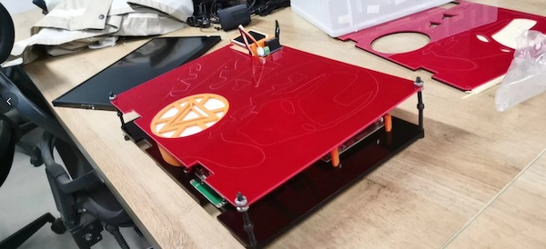
The system case design - 3D printing
This part is to make the work look good, tidy and logical.
- My Devices need to be supported, fixed and not moving everywhere. Thus I need to design some 3D parts holding them:
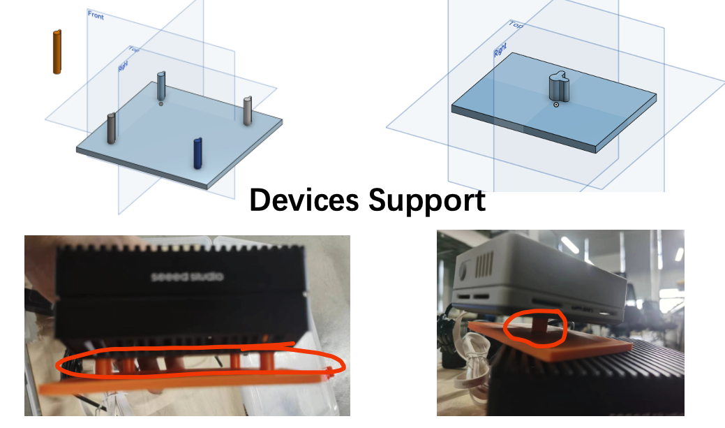
For other consideration, I remove the original.
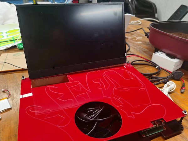
Updated with monitor and power adapter
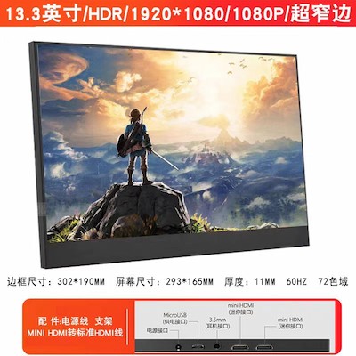
Continuing on the monitor, for the carrierable goal, I have to consider a carrierable monitor. I bought one and its size is showing by the producer:
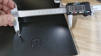
There are four screw holes in the back, and then I measured the distance from the screw holes to the edge and the distance between the holes:
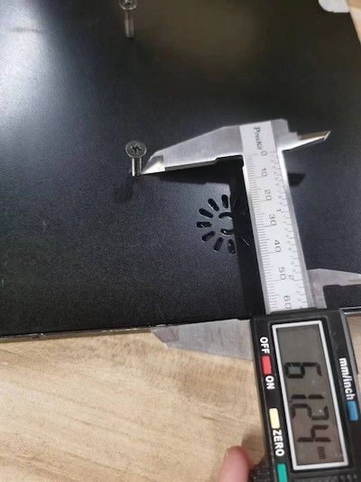
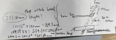
Then I need to calculate te length of the display board, where it must ensure that it is not too long to affect the appearance and not too short to connect:
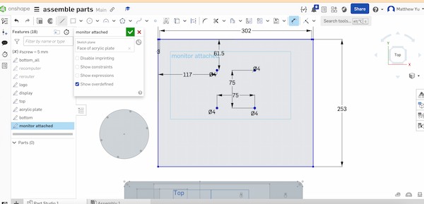
Later I design the attached board for monitor on the OnShape:
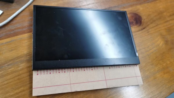
Laser cutting and done, looking fine on both sides:
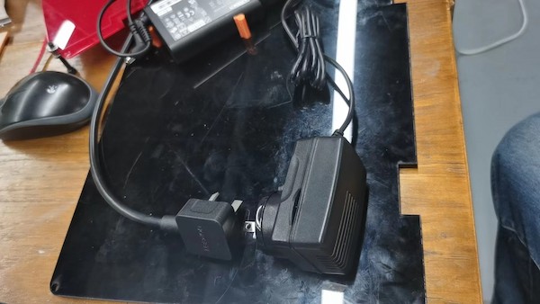
And for the power adapter I need to hold them tied as well:
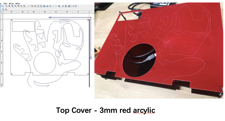
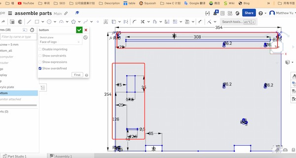
And considering the monitor, I need to design the gap on each plate, for the holding:
The bottom:
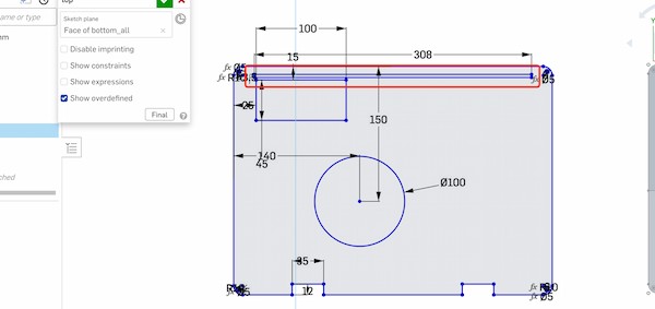
The top:
Cutting the board and insert the modules in it:
Screw it in. Almost done
Adding the mobile module:
Move them outsides: