(input) Mobile Module - Audio Input Case Design
Write something at the front
Updating on 6.26th, I am updating my mobile module design, which is included Iron Man Reactor Core. For the basic idea presenting, I will have three parts for my input module:
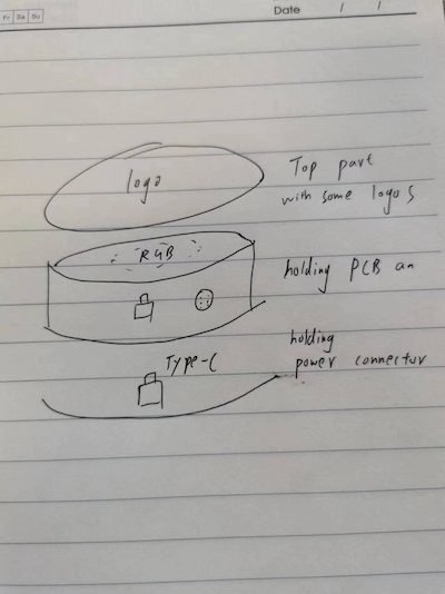
I would like to make it wireless someday, but now let's do it in wire.
The logo part is refering to this project. Actually this is my week13 assignment as well.
Files Sharing
Here is the Onshape link for my input design:
- Top part: Iron Man Reactor Core.
- Middle part: Between the preceding and the following
- Following part: Power connector fixing
Design the Top Part - updated
Updated on 7.6th, I found my previous demo module is bigger than my PCB board:
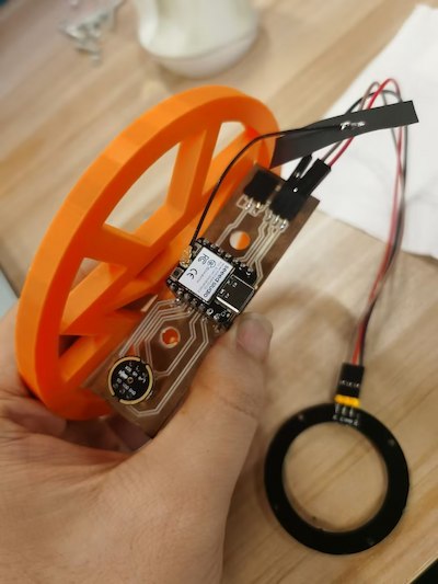
And my design should be reconsider, this can be the update for my week13.
I resize the outline.
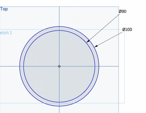
And something went wrong, like these designs I should pay more attention to its connection/joint.
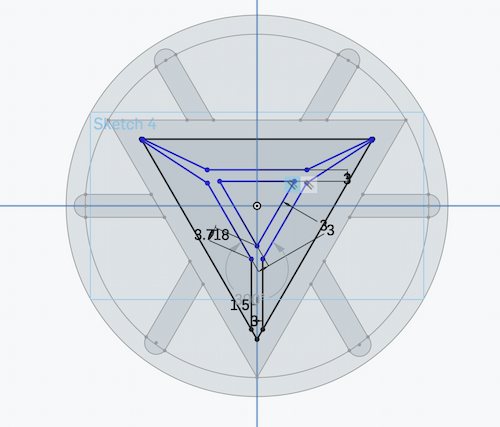
While adding more parameters, consider symmetry
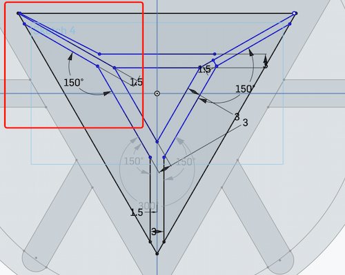
Looking fine
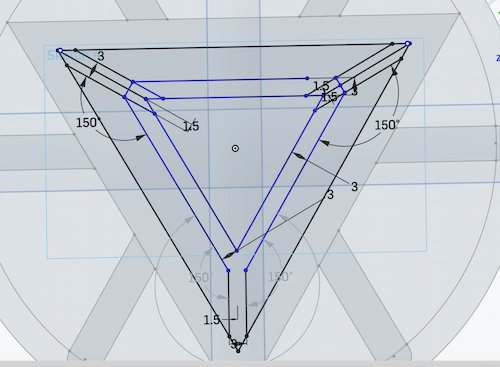
And removing sublines
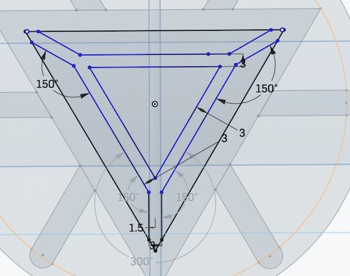
I designed some round holes to make it easier to connect later:
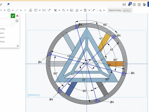
I want to put an acrylic plate to show the rgb, and letting it out will be not looking good. Hence I will design a smalle cover. The length will be deccided by the thickness of the board, which(Two 1.8 mm acrylic sheets) should be 3.6mm.
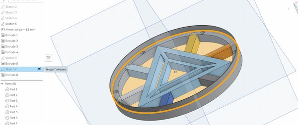
Design the Top Part
I create a new document on Onshape.

Raw drawing
I first want to make sure the steps that I draw them:
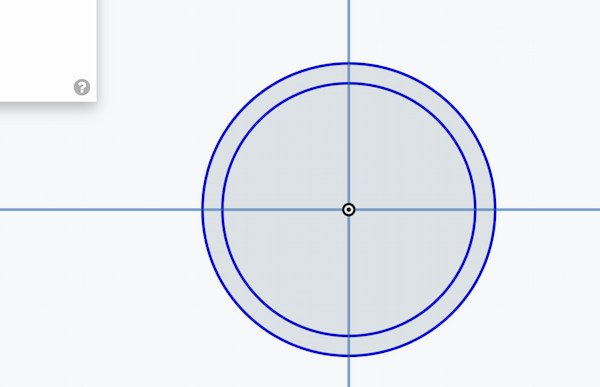
The concentric circles serve as the outer rings:
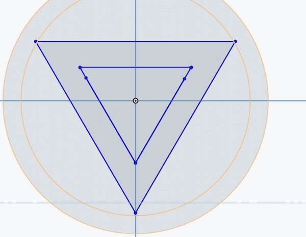
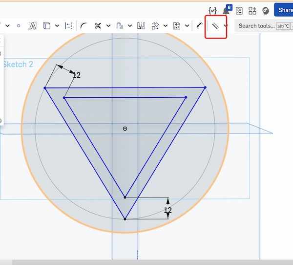
Parity triangle as intermediate core:
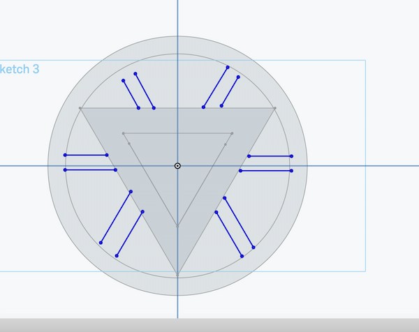
Some pillars for decoration:
Design the model according to the actual situation
I first calculate the length of my input board, for ensuring it can be put into the circle:
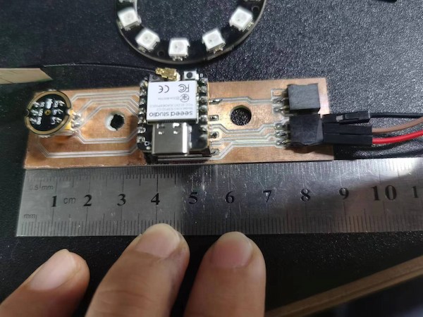
Since I will have other components to assemble, I will just measure this one: 99mm. This is because I will have the connectors for connecting RGB light on my board. Thus, 100mm is setting for ensuring.
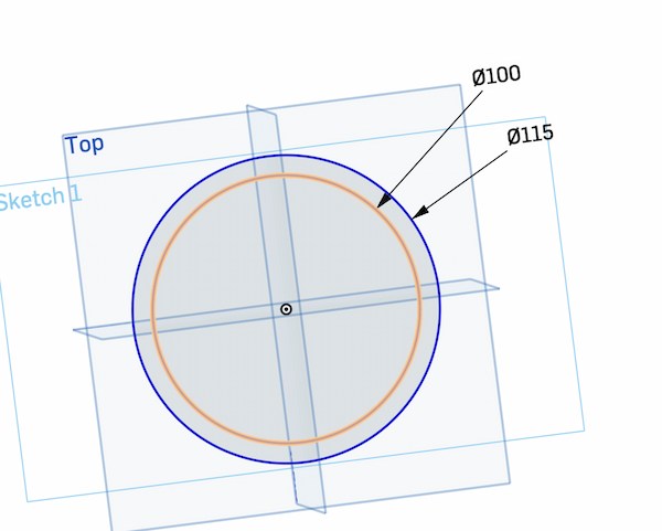
Align cluttered lines.
Adjust the angle and make it looking a little better:
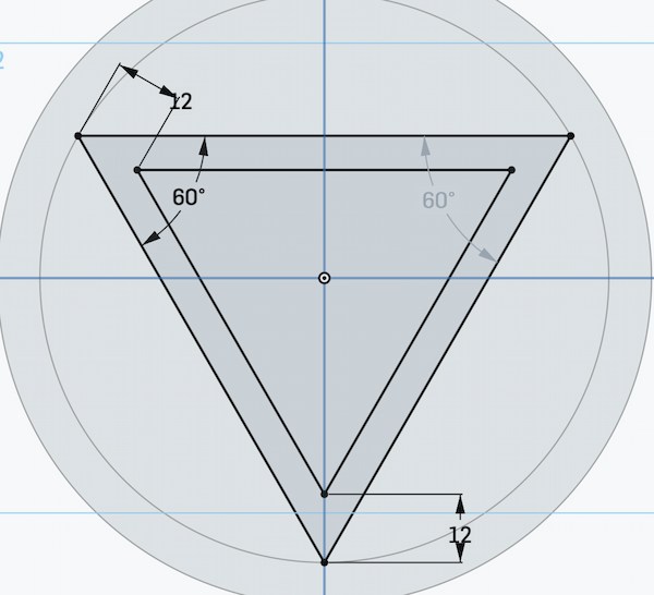
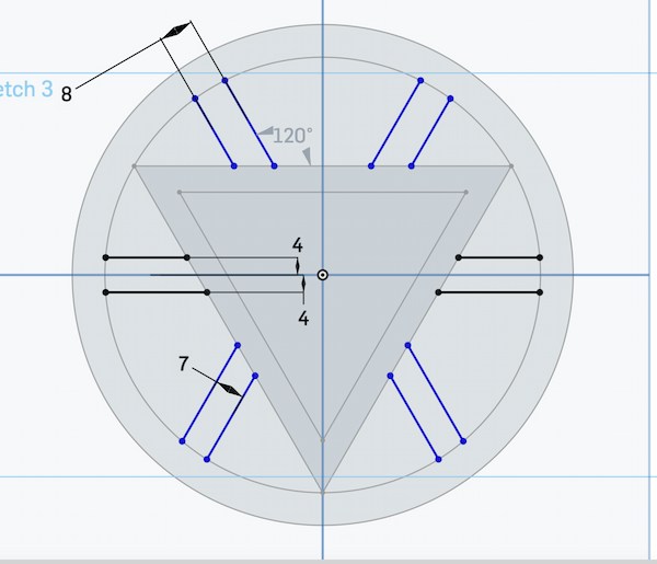
Adjust the length of the post and adjust the angle:
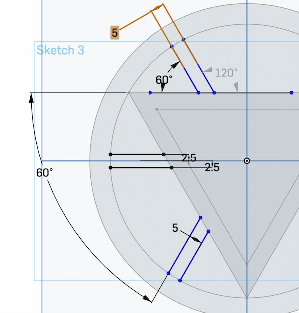
Using Mirror function to duplicate another part of the symmetry.
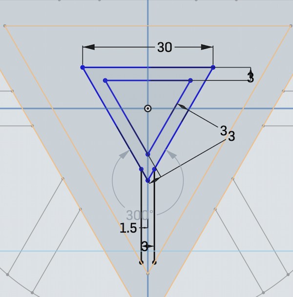
And then there's the little bit in the middle.
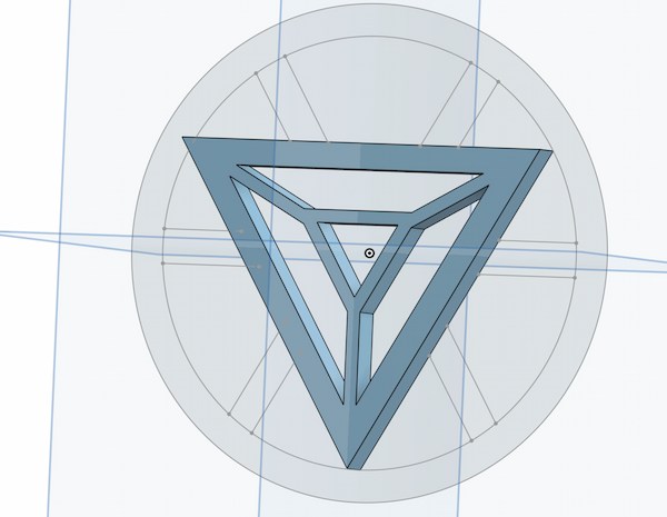
Now I can use Extrude function to make the parts, setting as 7mm:
The outside circles:
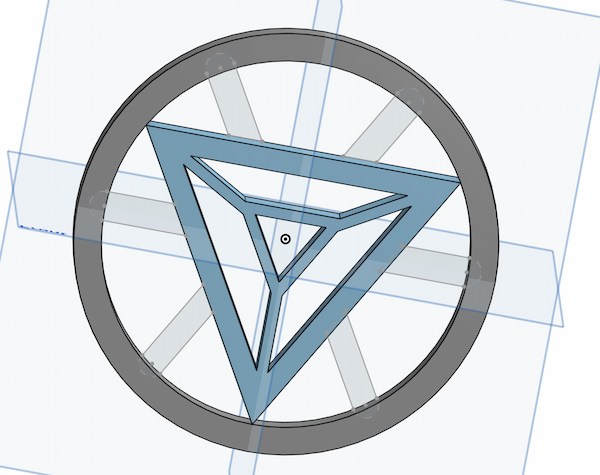
I forgot that I need to have closed shapes to do the parts:
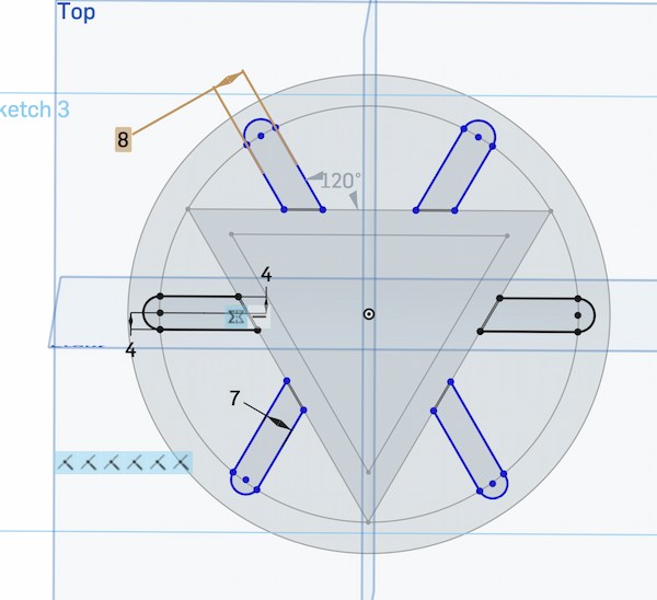
Why I am doing in different sketches. It is because I might need to adjust them in the future.
Finally, I have my parts:
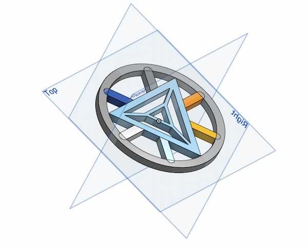
Printing with 3D printer
I am using 3D printer to print this part. I needed to be very fine, so I switched to the thinnest 0.2mm nozzle.
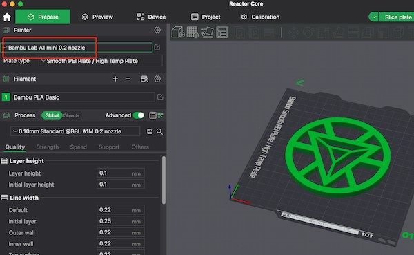
Requiring 4 hours, seems reasonable.
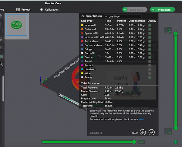
Done.
Design the Middle Part
The middle one is supposed to hold my PCB board, and at the same time carrying a RGB ring.
Design on the Onshape
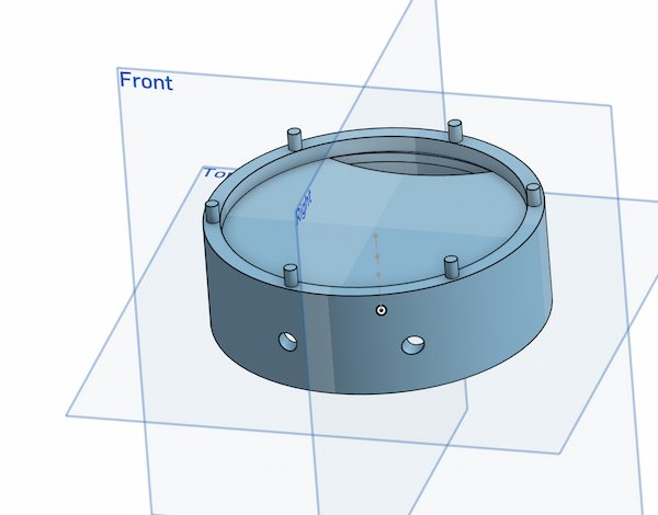
RGB acrylic plate
I need acrylic plate for preseting RGB better looking. Thus, I design some file on the Onshpe as well, using the same parameters:
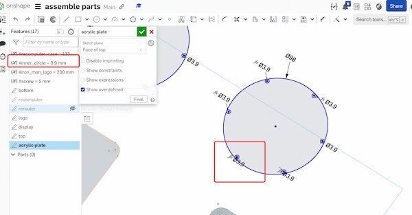
Integration
After all parts done, I can assemble them all together:
Put the PCB board and the supprt in it:
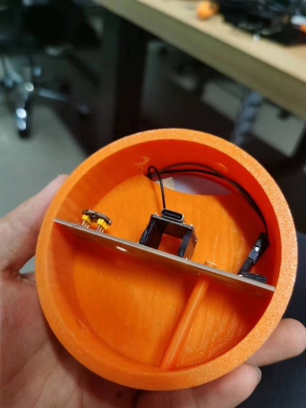
Extend the rgb lights out, along with XIAO antenna:
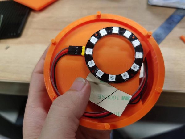
Finally put the acrylic plate init can cover it up:
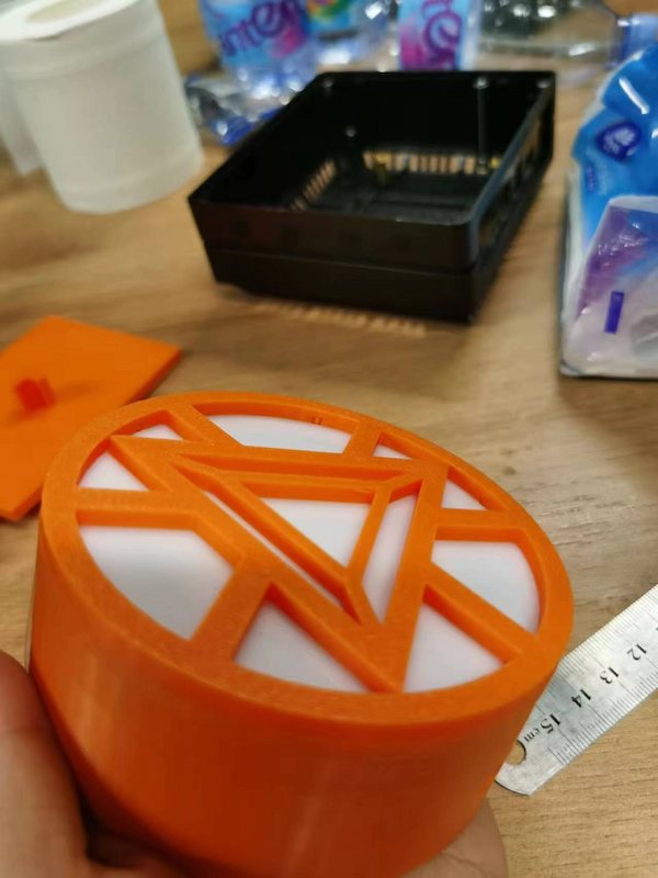
One simple model is done.