(input) Mobile Module - PCB design
Write something at the front
What I want to achieve is that when I power the board up or put a switch on, this module can record my words and then transmit them as a audio file. And at the same time, I have to consider what display that I might have, to show the connection with reComputer.
Thus, for my input PCB design board, I will have one INMP441 onabord, and two Conn PinHeader1x03 P2.54mm Horizontal SMD for connecting RGB displays.
Finally, I have to find a way to fix it, thus I might need some holes.
Design PCB on the KiCAD
I directly called the KiCAD file including INMP441 design on this GitHub. I download it and duplicate its design on my PCB, only the INMP441 part.
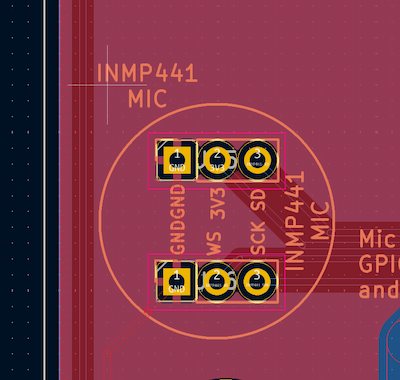
I am using Conn PinHeader1x03 P2.54mm Horizontal SMD to replace his PCB design.
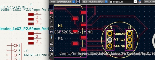
And I want to input XIAO-ESP32C3_SocketSMD for holding a battery in the future.
For some points, I am thinking the Grove Connecotor for connecting RGB display.
And the holes, for holding of course. Eventually I have this version
Later I think I might need more RGB displays, or have backup connections. And the most important thing is that the holes are not supposed be outsides.
I should reconsider it. Thus, for updates:
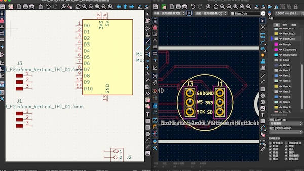
I add two more Conn_PinHeader_1x03_P2.54mm_Horizontal_SMD, and here is the final schematic diagram:
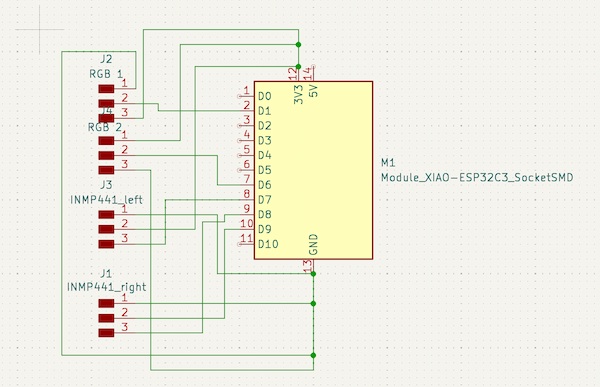
For making connection more easier:
- I make some changes about the connection. Giving any GPIO on ESP32 can be I2S, I switch
WSto9,SCKto8, andSDto20. - And I add two PinHeader connecting signal pin to
3and21.
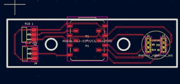
And this will be the final PCB looking:
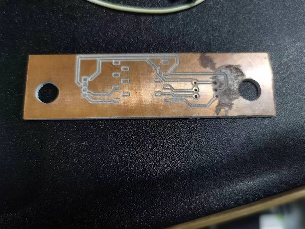
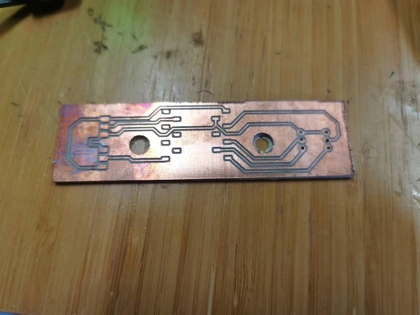
Milling...
There is the board:
And after soldering:
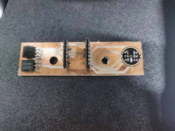
This is why I should have backups...
Connection Check
Anyway, the board is done and I can check the output:
Voice sampling and data sending:
This is the code I am using:
#include <WiFi.h>
#include <driver/i2s.h>

const char* ssid     = "fros_wifi";
const char* password = "66668888";

// Connections to INMP441 I2S microphone
#define I2S_WS 9
#define I2S_SD 20
#define I2S_SCK 8

// Use I2S Processor 0
#define I2S_PORT I2S_NUM_0

// Define input buffer length
#define bufferLen 64
int16_t sBuffer[bufferLen];

// Server configuration
WiFiServer server(12345);

void i2s_install() {
  // Set up I2S Processor configuration
  const i2s_config_t i2s_config = {
    .mode = i2s_mode_t(I2S_MODE_MASTER | I2S_MODE_RX),
    .sample_rate = 44100,
    .bits_per_sample = i2s_bits_per_sample_t(16),
    .channel_format = I2S_CHANNEL_FMT_ONLY_LEFT,
    .communication_format = i2s_comm_format_t(I2S_COMM_FORMAT_STAND_I2S),
    .intr_alloc_flags = 0,
    .dma_buf_count = 8,
    .dma_buf_len = bufferLen,
    .use_apll = false
  };

  i2s_driver_install(I2S_PORT, &i2s_config, 0, NULL);
}

void i2s_setpin() {
  // Set I2S pin configuration
  const i2s_pin_config_t pin_config = {
    .bck_io_num = I2S_SCK,
    .ws_io_num = I2S_WS,
    .data_out_num = -1,
    .data_in_num = I2S_SD
  };

  i2s_set_pin(I2S_PORT, &pin_config);
}

void setup() {
  // Set up Serial Monitor
  Serial.begin(115200);
  Serial.println("ESP32 I2S Microphone Test");

  delay(1000);

  // Set up I2S
  i2s_install();
  i2s_setpin();
  i2s_start(I2S_PORT);

  delay(500);

  // Connect to Wi-Fi
  Serial.println();
  Serial.println();
  Serial.print("Connecting to ");
  Serial.println(ssid);

  WiFi.begin(ssid, password);

  while (WiFi.status() != WL_CONNECTED) {
    delay(500);
    Serial.print(".");
  }

  Serial.println("");
  Serial.println("WiFi connected");

  // Print the IP address of the ESP32C3 MCU board
  Serial.println("IP address: ");
  Serial.println(WiFi.localIP());

  // Start the server
  server.begin();
  Serial.println("Server started");
}

void loop() {
  // Check if a client has connected
  WiFiClient client = server.available();
  if (client) {
    Serial.println("Client connected");

    // Get I2S data and place in data buffer
    size_t bytesIn = 0;
    esp_err_t result = i2s_read(I2S_PORT, &sBuffer, bufferLen, &bytesIn, portMAX_DELAY);

    if (result == ESP_OK) {
      // Read I2S data buffer
      int16_t samples_read = bytesIn / 8;
      if (samples_read > 0) {
        // Send the audio data to the connected client
        client.write((uint8_t*)sBuffer, bytesIn);
      }
    }

    // Close the connection
    client.stop();
    Serial.println("Client disconnected");
  }
}
RGB Displaying:
And by the way the code:
#include <Adafruit_NeoPixel.h>

#define PIN D1           // WS2812B LED连接的引脚
#define NUMPIXELS 1     // LED的数量
#define MAX_BRIGHTNESS 127  // 最大亮度值为127,约为50%

Adafruit_NeoPixel strip = Adafruit_NeoPixel(NUMPIXELS, PIN, NEO_GRB + NEO_KHZ800);

void setup() {
  strip.begin();
  strip.show();  // 初始化,将所有LED关闭
}

void loop() {
  // 渐亮至中等亮度
  for (int i = 0; i <= MAX_BRIGHTNESS; i++) {
    strip.setPixelColor(0, strip.Color(i, i, i));  // 设置为灰度亮度
    strip.show();
    delay(10);  // 延迟以制造渐变效果
  }

  delay(500);  // 在最亮时保持一段时间

  // 渐暗回到完全关闭
  for (int i = MAX_BRIGHTNESS; i >= 0; i--) {
    strip.setPixelColor(0, strip.Color(i, i, i));
    strip.show();
    delay(10);
  }

  delay(500);  // 在完全关闭时保持一段时间
}
All seems fine, now I can move to the case design.