Final Project, Electronic Design
For electronic design I wanted to made my PCB using eagle as usual, my PCB will do the following:
1- Control motor speed.
2- Control direction of rotation clock wise or counter clock wise.
3- Pause/Start rotation of the motor.
4- ON/OFF the power on the turntable.
5- Have power indication LED.
In order to power the body from the grid, I utilized an existing stepper motor without any identifiable serial number or additional information. Following a circuit diagram demonstrated in a video tutorial (link: video), I constructed a circuit on a breadboard using an ESP32-C3 microcontroller.
To initiate the testing process, I set the power supply to 5 volts with a current limit of 1 amp. Gradually increasing the voltage in small increments, I observed the stepper motor's behavior. It began rotating at around 7 volts, while smooth and consistent movement was achieved at approximately 8 to 9 volts.
Based on the test results, it was determined that the circuit requires a power supply capable of providing 12 volts and 2 amps. This voltage and current specification ensures optimal performance and reliable operation of the stepper motor within the circuit.
In this case I will use a Voltage regulator(from 12V to 5V) to power the MCU and the driver in addition to the following components:
1- MCU ESP32-C3.
2- MOTOR DRIVER.
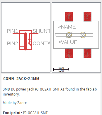
3- Power Jack.
4- SMD led.
5- 10mF SMD capacitors.
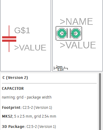
6- 100 mF through hole capacitor.
7- Resistors.
8- Pin headers
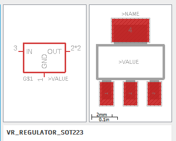
I have used this voltage regulator (how to add components on Electronic Design Week ):
This footprint for the through hole capacitor
The power jack footprint:
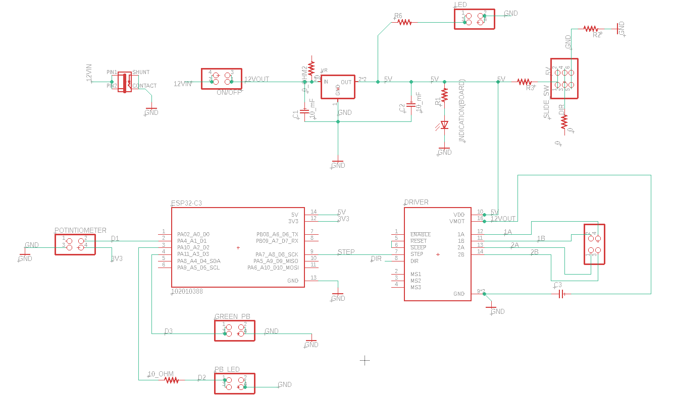
The schematic
After conducting several trials, I successfully traced all the routes on the board. I only needed to use a single zero-ohm resistor to bridge one trace. Although the board turned out to be slightly larger than anticipated, it is acceptable for the initial version. The key takeaway is that there is always room for improvement in future iterations.
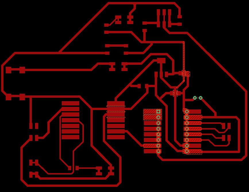
Trace image:
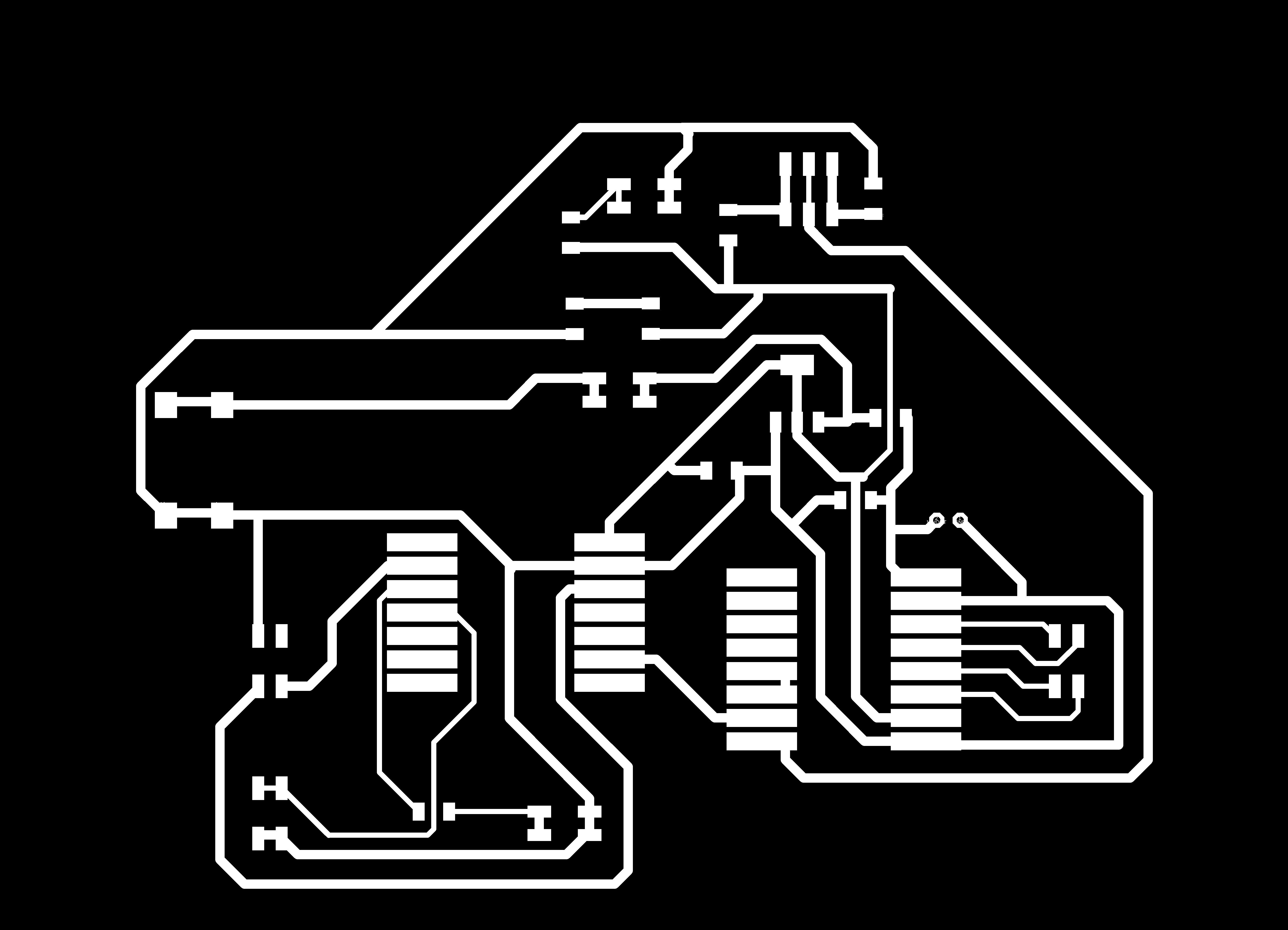
Final Outline: