Skip to content

14. Interface and application programming

This week I made an application with GUI to send commands to my microcontroller. While it's unlikely that my final project would need an application, it was still nice to learn the very basics of PyQt as that is a powerful tool for all future python application / interface needs.

Group work

For this weeks group work we decided to work together as one group to cover more platforms and share the learnings. Each member chose atleast one way of making an application for their embedded device to communicate with.

Programming

I wanted to use python as it's both familiar and I think it makes the most sense of the options I know. For the interface I went with PyQt as that's something I have wanted to learn for a while and finally had a good motivation to do so.

So the plan is to make an application that communicates with my microcontroller. At the end I set the program to send a '1' or a '0' to turn the LED on/off. The microcontroller would return a more complex message "LED,0,1" or "LED,0,0" indicating that the command has been received. Additionally a newline symbol \n would trigger the microcontroller to send the status of the LED without changing it. This allowed the program to ask for the status when needed.

Python

I had to install the following python packages

  • PyQt5
    • Graphical User Inteface (GUI)
  • PySerial
    • Serial communication with the microcontroller
  • PyInstaller
    • Building an executable

Before installing those I went ahead and created a python virtual environment:

> python -m venv myvenv
> .\myvenv\Scripts\activate

Keep in mind that I'm using Windows Powershell.

So now the command line would look something like this

(myvenv) PS C:\Users\Akseli>

To deactivate the venv, just type deactivate.

This now allows me to install whatever libraries, packages and dependencies I need for this specific project and keep them separated from other projects on my computer.

So only after that I could install the needed packages:

> pip install pyqt5
> pip install pyserial
> pip install pyinstaller

PyQt5

I began by swiftly going through atleast the beginning of this tutorial-

From that tutorial this example was the bare minimum to get the beginnings of an application running:

import sys

from PyQt5.QtCore import QSize, Qt
from PyQt5.QtWidgets import QApplication, QMainWindow, QPushButton


class MainWindow(QMainWindow):
    def __init__(self):
        super().__init__()

        self.setWindowTitle("My App")
        button = QPushButton("Press Me!")

        self.setCentralWidget(button)


app = QApplication(sys.argv)

window = MainWindow()
window.show()

app.exec()

Running it via python myapp.py looked like this.

First application

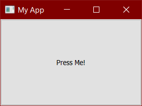
Not so breathtaking quite yet, but it's a start.

I continued the tutorial and learned things like how to add widgets like buttons or labels, and layouts to position those. Further, I learned how to connect signals from these widgets, like button presses, to my own python methods. Now I could actually make the buttons do something.

Finalized application

PySerial

To allow the python application to communicate with the microcontroller I used the PySerial module. From that website this short introduction was enough to know how to use it for my application.

So naturally need to instance the serial.

myserial = serial.Serial()

Then only later configure COM port and open.

myserial.port = "COM" + str(my_com_port)
myserial.open()

And finally when disconnecting the serial.

myserial.close()

So, how to know which COM port to use?

You could use something like the Device manager in Windows, but PySerial happens to come with this nice tool python -m serial.tools.list_ports to list available ports.

Before unplugging the microcontroller:

(venv) PS C:\Users\Akseli> python -m serial.tools.list_ports
COM1
COM4
2 ports found

After plugging in the microcontroller:

(venv) PS C:\Users\Akseli> python -m serial.tools.list_ports
COM1
COM4
COM5
3 ports found

So now I know the port for that microcontroller on this computer is COM5.

One thing I did not figure out was how I could use this module tool from the python program. It would allow me to list the available ports as a drop-down menu in the application. However, for this I think it's sufficient to have only the number selection.

Result

Now I also have what I need to make this application. Naturally the microcontroller code was made on the side, but let's got through that after the python.

I am aware that not all the code should be under the only class, but I found that to be the quickest way to get this program together. It can always be improved later™.

So here is the entire python program:

aplikaatio.py
import sys
import serial

from PyQt5.QtCore import QSize, Qt, QTimer
from PyQt5.QtWidgets import QApplication, QMainWindow, QPushButton, QLabel, QLineEdit, QVBoxLayout, QHBoxLayout, QSpinBox, QWidget


class MainWindow(QMainWindow):
    def __init__(self):
        super().__init__()
        self.show()

        #self.led_is_on = False
        self.connected = False
        self.serial = serial.Serial()
        self.com_port_num = 4

        # Window
        self.setWindowTitle("LED controller")
        self.setFixedSize(QSize(400, 300))

        # Top bar
        com_label = QLabel("COM")
        com_label.setMinimumWidth(30)

        com_port = self.com_port_input = QSpinBox()
        com_port.setValue(self.com_port_num)
        com_port.valueChanged.connect(self._on_com_port_value_changed)

        connect_button = self.connect_button = QPushButton("Connect")
        connect_button.setCheckable(True) # Toggle button
        connect_button.clicked.connect(self._on_connect_button_pressed)

        baud_label = QLabel("9600 BAUD") # This is not changed
        baud_label.setMinimumWidth(80)

        top_bar = QHBoxLayout()
        top_bar.addWidget(com_label)
        top_bar.addWidget(com_port)
        top_bar.addWidget(connect_button)
        top_bar.addWidget(baud_label)
        top_bar.setAlignment(Qt.AlignLeft | Qt.AlignTop)

        # Status Label
        status_label = self.status_label = QLabel()
        status_label.setAlignment(Qt.AlignLeft | Qt.AlignTop)

        # LED Button
        led_button = self.led_button = QPushButton("LED")
        led_button.setCheckable(True) # Toggle button
        led_button.setEnabled(False) # Cannot press the button when not connected
        led_button.clicked.connect(self._on_led_button_pressed)

        # Layout
        layout = QVBoxLayout()
        layout.addLayout(top_bar)
        #layout.addWidget(text_input)
        layout.addWidget(status_label)
        layout.addWidget(led_button)

        # Container
        container = QWidget()
        container.setLayout(layout)

        # Set the central widget of the Window.
        self.setCentralWidget(container)

        # Timer for reading the serial port
        self.serial_timer = QTimer()
        self.serial_timer.setInterval(500)
        self.serial_timer.timeout.connect(self._on_serial_timer_timeout)


    def _on_led_button_pressed(self, checked):
        if not self.serial.is_open:
            return
        if checked:
            #print("Turning led on")
            #self.led_is_on = True
            self.serial.write(b'1')
        else:
            #print("Turning led off")
            #self.led_is_on = False
            self.serial.write(b'0')


    def _on_connect_button_pressed(self, checked):
        if checked and not self.serial.is_open:
            # Try to connect to serial
            self.serial.baudrate = 9600
            self.serial.port = "COM" + str(self.com_port_num)
            #print("COM" + str(self.com_port_num))
            try:
                self.serial.open()
            except serial.SerialException:
                #print("Failed to connect")
                self.connect_button.setChecked(False)
                self.status_label.setText("Failed to connect")
                return
            self.status_label.setText("")
            #print("Connected")
            self.connect_button.setText("Connected")
            self.com_port_input.setEnabled(False)
            self.led_button.setEnabled(True)
            self.serial.write(b'\n')
            self.serial_timer.start()
        elif self.serial.is_open:
            # Disconnect serial
            self.serial_timer.stop()
            self.serial.close()
            #print("Disconnected")
            self.connect_button.setText("Connect")
            self.com_port_input.setEnabled(True)
            self.led_button.setEnabled(False)
            self.led_button.setText("LED")


    def _on_com_port_value_changed(self, value):
        self.com_port_num = value

    def _on_serial_timer_timeout(self):
        if not self.serial.is_open or not self.serial.in_waiting:
            # Nothing to read
            return
        message = ""
        while self.serial.in_waiting:
            # Read byte and add to string
            message += self.serial.read().decode('utf-8')
        # Remove possible newline characters and split to arguments
        data = message.strip('\r\n').split(',')

        if data[0] == "LED" and data[1] == '0':
            # Information is about LED index 0
            if data[2] == '1':
                # The LED has been turned on
                self.led_button.setChecked(True)
                self.led_button.setText("LED is on")
            elif data[2] == '0':
                # The LED has been turned off
                self.led_button.setChecked(False)
                self.led_button.setText("LED is off")


app = QApplication(sys.argv)

window = MainWindow()

app.exec()

The last addition was that timer to read the serial port.

I will present the application in a later section.

Microcontroller

Embedded programming was documented earlier in week 4. Some additional details of the serial communication were also presented on the previous week.

For this week I simply needed the microcontroller to act on predefined commands to turn on / off the NeoPixel (or other LED). There is not much new to that but I made the code myself.

Here is the finalized program on the microcontrollers side.

serial-led.ino
#include <Adafruit_NeoPixel.h>

#define IROUTPUTPIN D0 // IR diode on my custom PCB

// Made for RP2040
#define NEOPOWERPIN 11 // Provides voltage for the built-in NeoPixel
#define NEOPIXELPIN 12 // Datapin for the the built-in NeoPixel

#define NUMPIXELS 1 //Amount of NeoPixels

Adafruit_NeoPixel pixel(NUMPIXELS, NEOPIXELPIN, NEO_RGB + NEO_KHZ800);

#define DELAYVAL 100

bool led_on = false;

void setup() {
  pinMode(LED_BUILTIN, OUTPUT); // Initialize digital pin LED_BUILTIN as an output.
  pinMode(IROUTPUTPIN, OUTPUT); // Initialize the IR pin as an output.

  pinMode(NEOPOWERPIN, OUTPUT); // Initialize digital pin NEOPOWERPIN as an output.
  digitalWrite(NEOPOWERPIN, HIGH); // Power for the NeoPixel
  pixel.begin();

  Serial.begin(9600);
}

void loop() {
  if (Serial.available()) {
    char char_in = Serial.read(); // Read one character
    //Serial.write(char_in); // Return the character for debug

    if (char_in == '1') {
      // Turn led on
      pixel.clear();
      pixel.setPixelColor(0, 150,100,50);
      pixel.show();
      led_on = true;
      Serial.println("LED,0,1"); // Send confirm
    } else if (char_in == '0') {
      // Turn led off
      pixel.clear();
      pixel.show();
      led_on = false;
      Serial.println("LED,0,0"); // Send confirm
    } else if (char_in == '\n') {
      // Send status of the led
      if (led_on) {
        Serial.println("LED,0,1");
      } else {
        Serial.println("LED,0,0");
      }
    } else {
      // Blink only the small built-led
      digitalWrite(LED_BUILTIN, LOW);
      delay(DELAYVAL);
      digitalWrite(LED_BUILTIN, HIGH);
      Serial.println("Not recognised");
    }
  }
  delay(DELAYVAL);

  /*
    To meet the requirements, I added this to blink
    the IR led I have on the PCB I made in week 8.
  */
  if (!led_on) {
    digitalWrite(IROUTPUTPIN, !digitalRead(IROUTPUTPIN));
  }
}

Also link to the code file here:

Building

Here is the link to the python code file:

This command will create an executable file (.exe on Windows) under ./dist/ directory:

(myvenv) C:\Users\Akseli\somewhere> pyinstaller --onefile aplikaatio.py

It takes a moment to build. After that the .exe is all you need. The PyQt is kind of overkill for this kind of application and there is some amount of unnecessary overhead which results the application .exe file size being around 35 MB. Not huge but still too much to upload on this site.
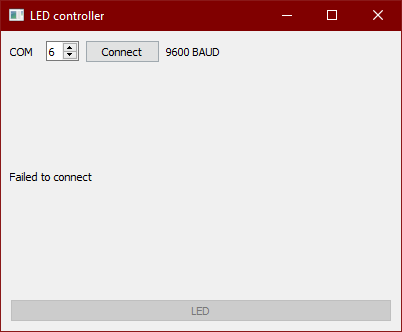
Final result

Here is the demonstration using the built .exe file.

Notice how the led status is updated correctly upon reconnecting. Also trying to connect to an unavailable port does not cause crash. Main attraction of this simple beginnings of an application is the user experience with the buttons. Meaning, that you cannot click the wrong buttons and the buttons tell you information that you need without cluttering the window.

There was some modifications needed as the assignment required the use of a self-made pcb. In my PCB the only output I have is the IR led, so I used that. I made the changes to the code (commented) and here is a video showing it working:

End of week 14.