3. Computer-controlled cutting
Laser cutting
I will first go through the design process and then explain in detail the fabrication steps.
For this I want to try and experiment making a new kind of joint. When I saw the image of different joint types in the global lecture I thought what if those last two were combined.
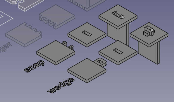
The snap joint is rather good but depending on the material I think it lacks strenght. Issue is that the clips have to be really thin to bend enough or the clipping surface be small so it doesn't need much bending. So there needs to be a balance between those. When working correctly it's easy to assemble.
I know from a personal experience that the wedge joint can result in very rigid structures. However, it is not the easiest to put together and might need thightening later (Good in a sense it can be thightened as it loosens). Also the joint protrudes quite a lot to the outside which might be unwanted.
First I will go through the design process and explain usage of the laser in the later sections.
The design
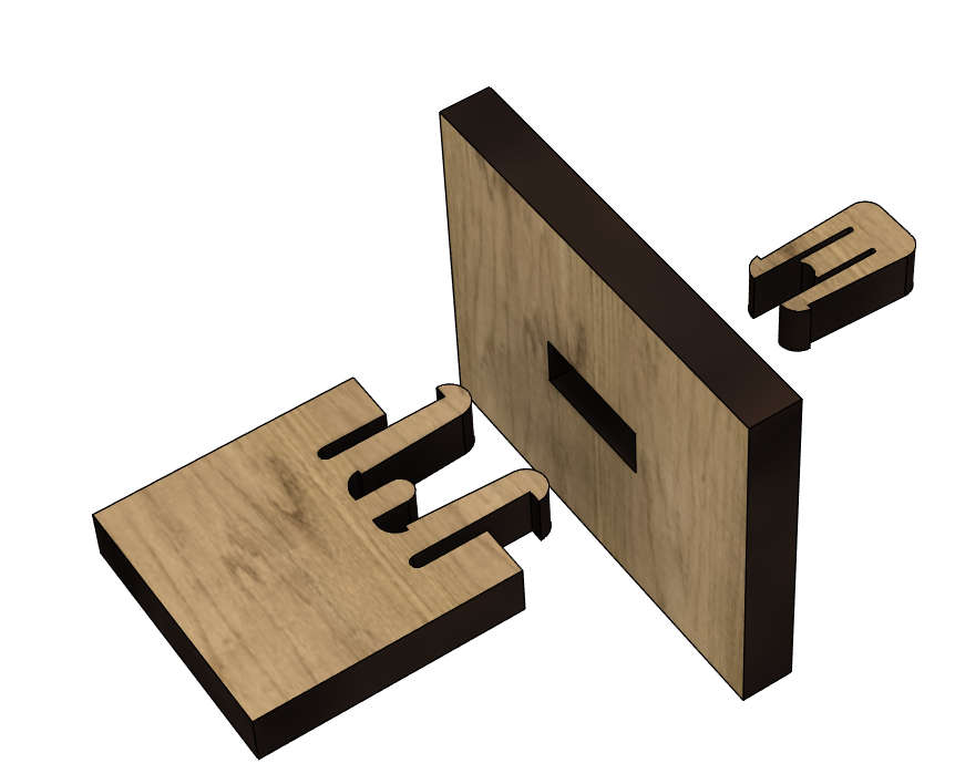
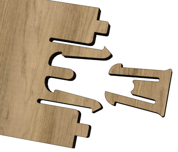
For the sake of over-engineering, I came up with an idea for a permament snap joint with a locking wedge:
This first quick iteration I did cut with the laser but it was way too small and fragile. It flew to trash bin before even taking a photo..
After that I came up with the idea where to actually use this joint. I also remade the joint.
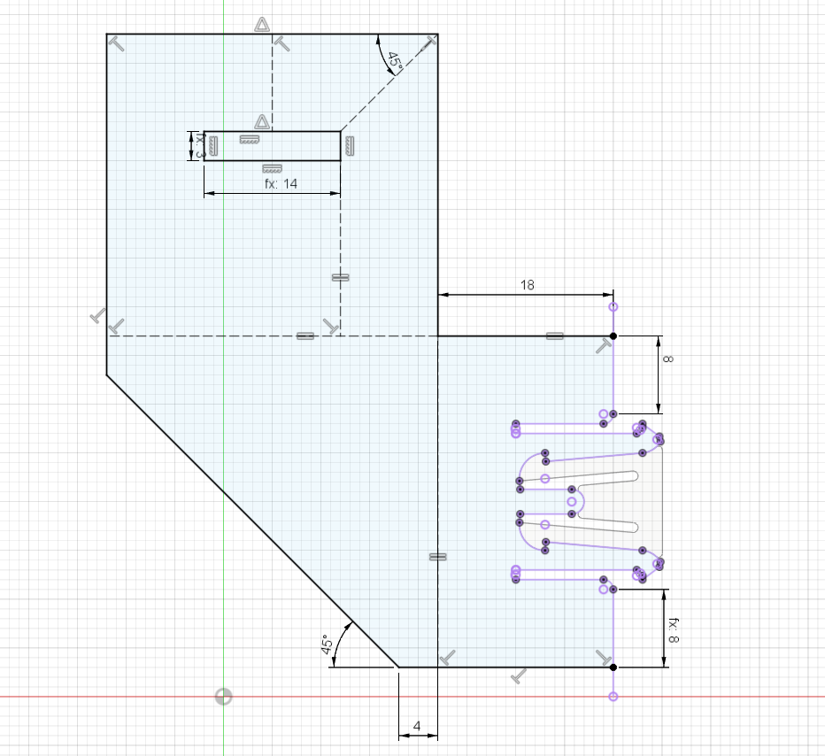
For that sketch I first made the parts of the joint as separate sketches.
Then I used project when inside that sketch to reference the previous sketches.
I did the same for the wedge piece (reference the shape where the wedge will be inserted) Here is the extruding of the wedge:
After extruding I used fillet to round the edges.
I went to more details on the 3D modeling operations in the previous week.
First laser cut iteration piece:
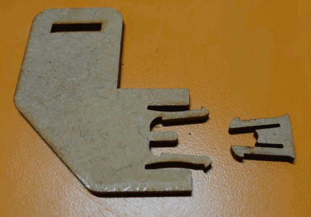
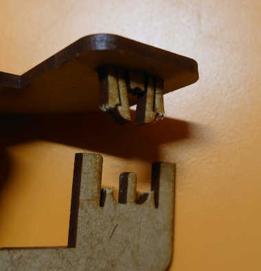
There the idea worked in a way as you can see:
So the main benefit of this joint is that it allows quick assembly and possibility to dismantle before locking in with the wedge. However, it's not yet good enough as the wedge locks wouldn't fully engage.
Additionally this design was still too fragile:
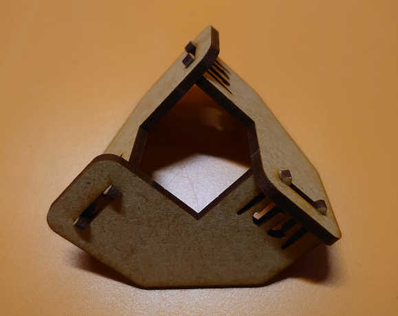
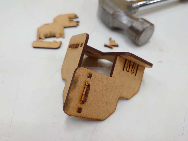
So I made the sides larger and added extra tabs to secure the joint.
Now that resulted in a very rigid design which still was possible to assemble even in this interlocked shape.
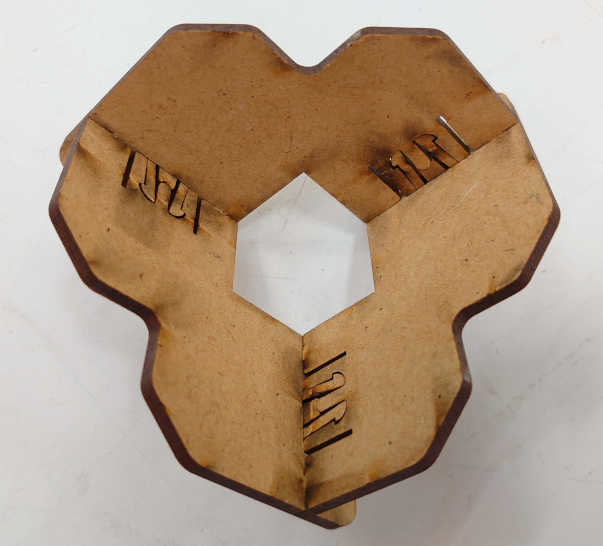
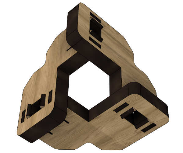
And here is the final product:
This can of course be assembled in different shapes too. Thus, consider it a "kit". Still I think this corner shape is the most usefull as it has many possible uses:
- Painting stand (stable, very low contact surface)
- Stand for a cube (eg. Rubics)
- Protect edges of a box
- Fasten a box with addition of rope
- Using those notches to grip the rope
Future improvements could possibly include flipping the wedge hooks. Currently the primary snapping flexure is weakened by the sharp edge.
Parameters
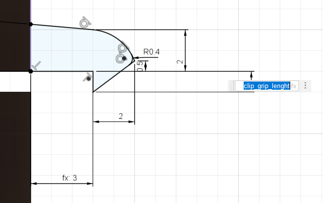
Here are the parameters I used in the design:
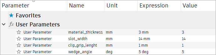
I have made the effort to name the parameters to be as self-explanatory as possible.
Like the material_thickness and slot_width.
wedge_angle means the steepness of the wedge.
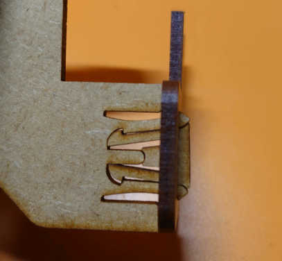
However I can see that the clip_grip_lenght needs some further elaboration.
It is the lenght of the "theeth" of the clip of the flexture.
Here is an image of the usage:
You may notice that the kerf isn't listed in the parameters. That will be in a later section.
Source file
Here is the source file.
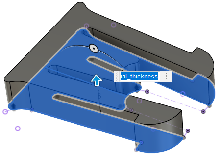
Note, that while it is indeed parametric the design is quite complex. Therefore, changing the values might be somewhat limited in success. I redesigned the whole thing twice. Here is still proof that at least the material thickness can be changed:
I don't adjust the kerf in the 3D model. That will be explained in the next section.
3D model to 2D vectors
There are were many ways to do this.
During my journey with Fusion I have went through them all.
Forget saving as dxf.
Forget accounting for kerf in modeling.
Forget exporting drawing as PDF (seriously don't do that).
This method handles the kerf for you
by using the manufacture or CAM workspace in fusion.
In short, when set up it's as simple as:
- Create a manufacturing model
- Flatten the models on the X/Y plane (in the manufacturing model)
- For multiple pieces you can use the arrange feature
- Create a setup and toolpaths (laser)
- Export or "post process" svg (embedded in HTML)
- Change
.htmlto.svg(post cannot change the file extension) - Open, edit (if needed) in Inkscape and save as pdf
Now, Autodesk provides this "post" for Epilog lasers which outputs svg embedded in HTML OR svg with the wrong file extension. That is exactly what allows us to use the powerful CAM tools of Fusion 360 for laser cutting.
Direct link to the Epilog post code
Kerf
The kerf setting is best explained in the video below, specifically at 2:00 timestamp. This image shows the tool library:
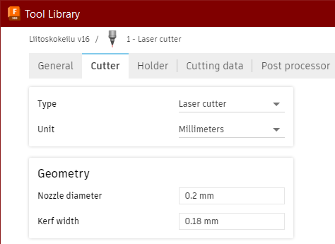
So the kerf is taken into consideration with the diameter of the tool used when making the toolpaths. The video below shows where this is found.
The right way (video)
In this video I go through the proces along with the needed setup. So you will need to download the post to follow along.
Sidenote: Had some problems when trying to reduce framerate. Thats why the bitrate had to be lowered to 80kb/s. It's also quite long but now its about 3MB. It's worth every byte.
However, atleast in our Fab Lab, it never works when trying to print the HTML file from a browser. That's why there is an extra step separating the svg from the HTML file. I will share a fix to that next.
Modifying the post
Note that it is not necessary modify the script.
The post is written in JavaScript if you want to modify it you can do it. The main thing you could change is the file extension:
extension = "html";
mimetype = "text/html";
To
extension = "svg";
mimetype = "image/svg+xml";
I have made my own modifications to the post I use but due to the licencing being very confusing I am afraid I can't share that as is. I'm open to advice.
Resulting file
 (Right-click to download source svg)
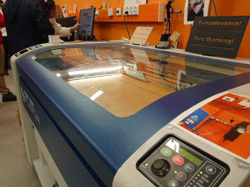
Sending files to the laser cutter
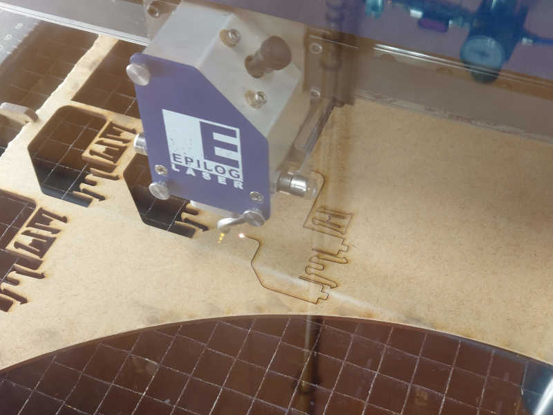
Here is our Fab Lab's laser cutter:
First step is to bring the files (.pdf and .svg just in case) to the computer.
Open the .pdf and click print ctrl + p. In the print menu select properties:
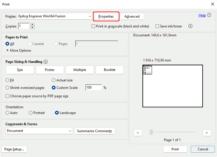
It opens this Epilog settings panel where you can set for example the power and speed for the cutting.
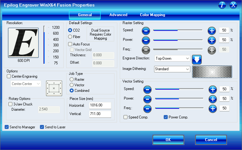
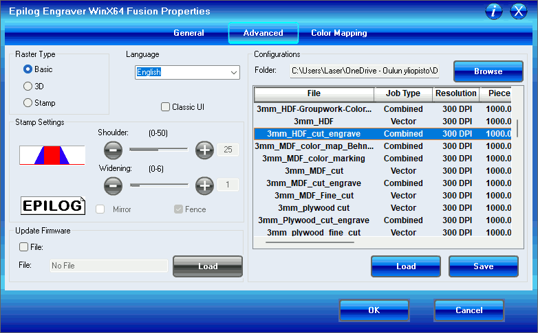
From the Advanced tab you can find premade configurations for different materials and thicknesses.
Here you need to click Load to use the settings. That will change the settings seen on the General tab.
When you "print" the file it is sent to the laser along with the settings you chose in the epilog settings panel.
Operating the laser cutter
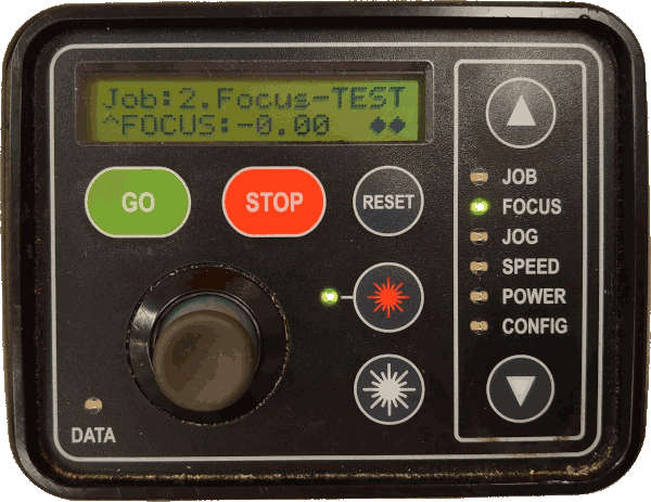
When you have sent the file you want to cut go to the laser control panel. There you can move between the menus with up/down arrows and do actions with the joystick.
The top three menus are the relevant ones: Job, Focus and Jog.
Focus is for height, jog is for X/Y, and job is selecting the file to cut.
I usually go through those in the following order, starting with focus.
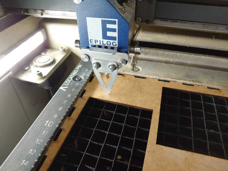
Here using the joystick you can raise/lower the table. This is to get the focal point of the laser as close as possible to the surface of the material.
Place the aluminium triangle on the laser head as show in the image below. Adjust the table height so that the tip of the triangle just touches the material you are going to cut.
When in the Jog menu moving the joystick moves the laser horizontally.
Move the head where you want the origin of the cut to be.
By default, this is the top-left corner of the pdf file.
Press down on the joystick to set the origin.
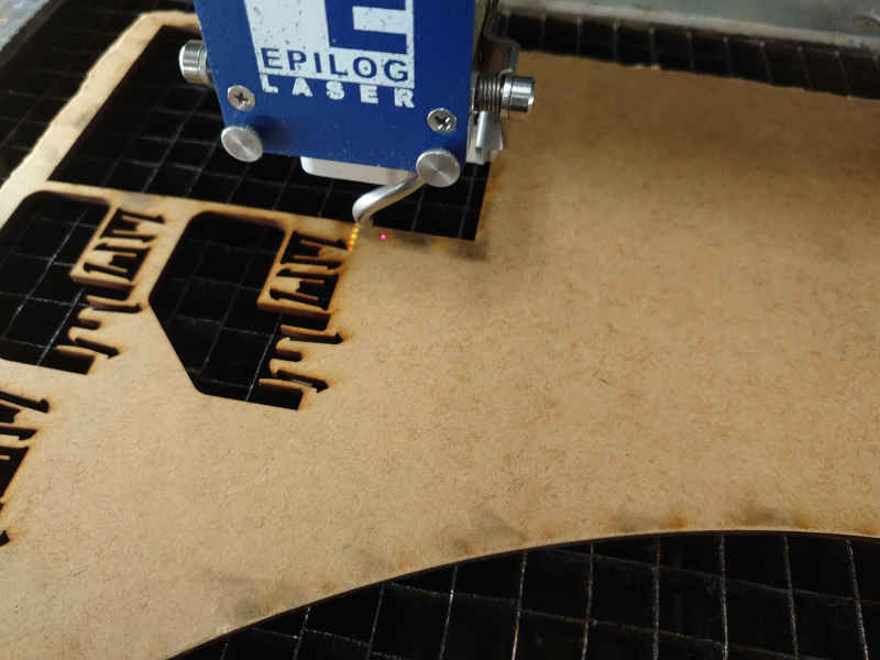
Note: If you cannot see the red marking laser press that red laser button.
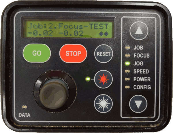
After pressing down on the joystick it will jump to the Job menu.
Here you can select the file you want to cut. It shows a running numbering
and the start of the filename. Also there is an estimate on how long the operation will take.
VERY IMPORTANT: Check that both the suction and air pressure is turned on before proceeding! There are instructions on the machine where to check those.
When you are sure that air and suction is on and you have set the jog and focus by pressing GO
the machine will start cutting.
If it shows zero on the time there is probably something wrong with the file. However, I didn't encounter that issue this time. Here is the cutting in progress:
After the operation has finished wait a while (~1 min) so the gasses vent.
Vinyl cutter
I went with the No symbol which I downloaded from the same wikipedia page.
 (Right-click to download source svg)
Preparation
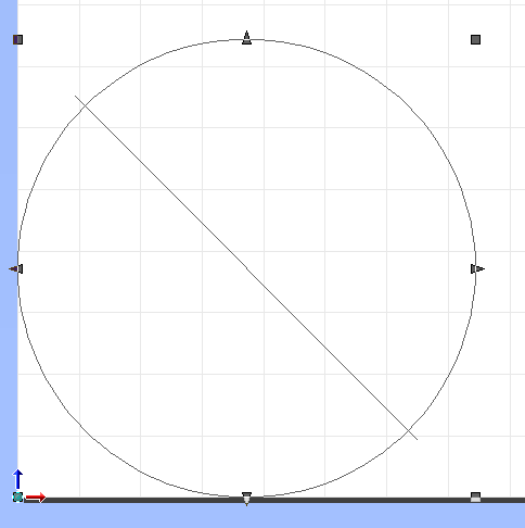
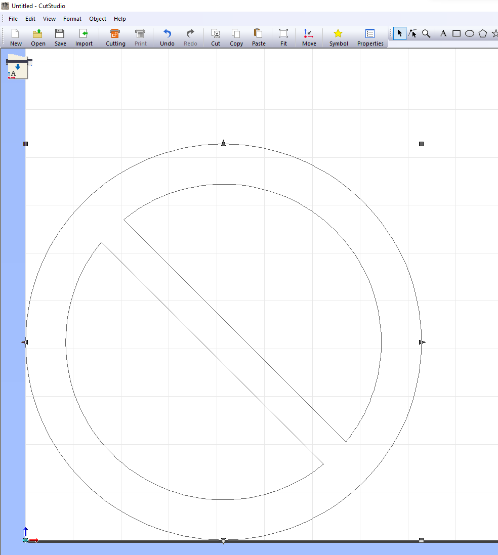
However as it turns out the file wasn't really ready for the cutter. Instead of a "shape" its just a thick circle and a line. This would cut accordingly, which is not the desired result:
Luckily this was rather quick to fix with this one operation in Inkscape called stroke to path.
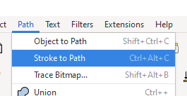
I also combined the circle and line with Path > Union
With that I could open proceed to the next step Extensions -> Roland Cutstudio -> Open in
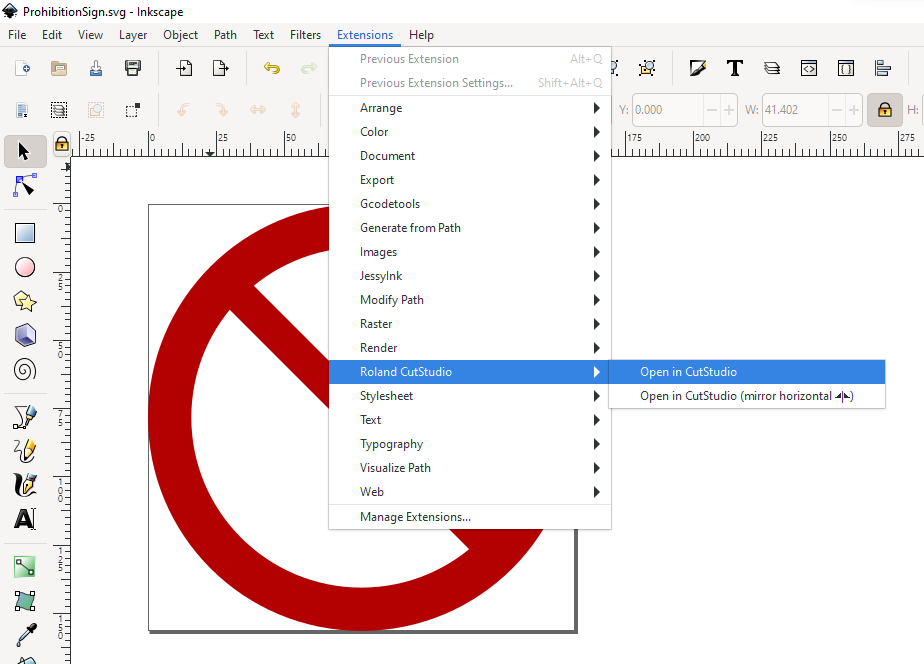
Important: In program the origin is bottom left instead of top left.
If everything looks as is should to cut go to Cutting > Ok. Note that this will start the cutting!
Cutting
Here is the device. You can see the locking lever behind the machine close to the monitor.
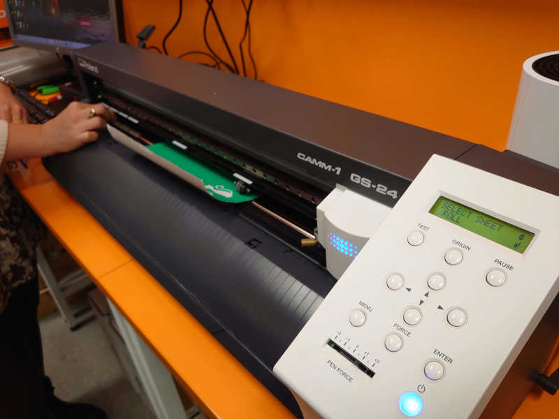
To use the vinyl cutter:
- Turn it on
- Unlock the rollers and insert your material.
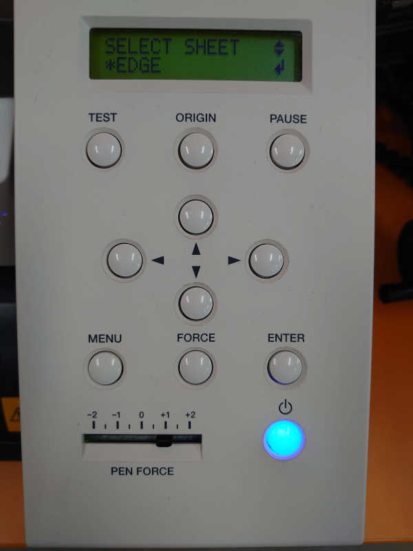
- Select which kind of piece to cut (roll/piece/edge)
- I used edge as it seems easiest.
- Confirm with enter.
- Move the head with the arrows
- Set origin point by holding the button
- Initiate the cut from the computer
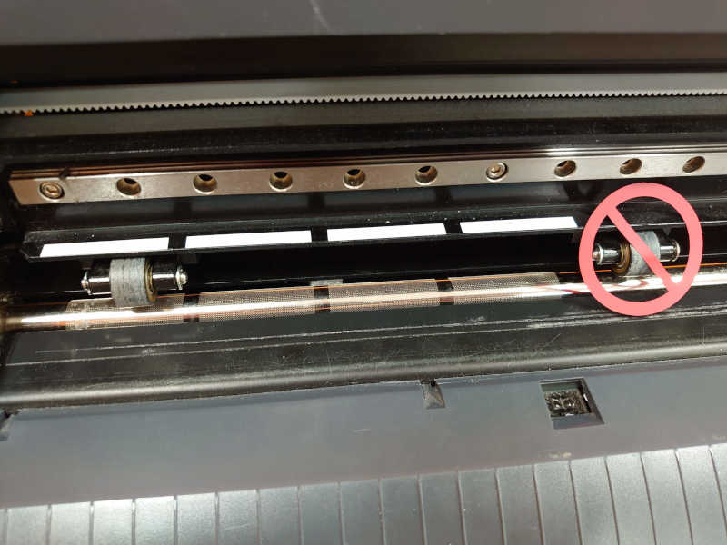
Here is a closeup of the operation:
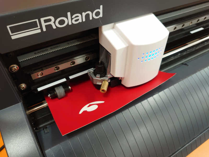
This product gives its user great power, as anything you put it on will be prohibited. Here I demonstrated that The rollers need to be on those white marks. I think the metal bar is what moves the material in and out and if the rollers are not on those grippy parts the material would slip. The rollers can be moved by hand when the material lock is lifted.
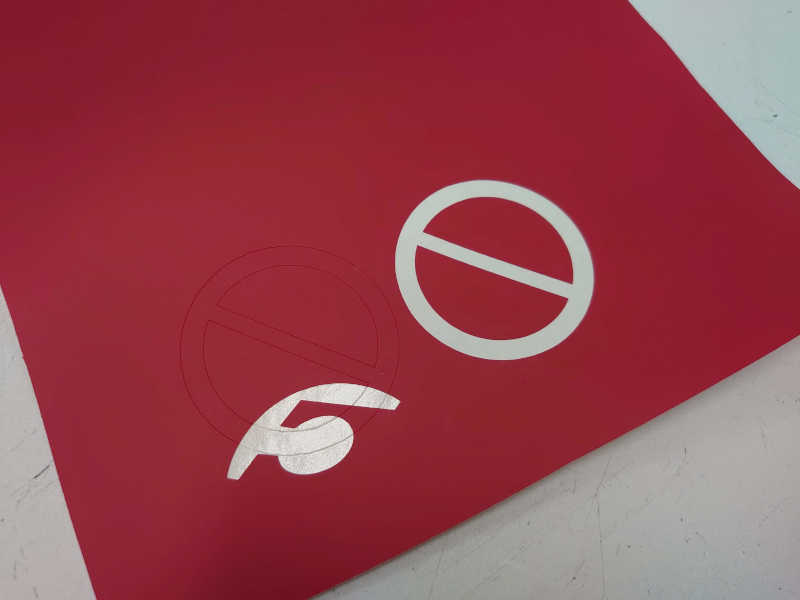
Result
Below is the leftovers from the operation. I think the vinyl cutter very easily wastes some material as the rollers need space and also the cutting head doesn't want to go at all close to the edge. At first I accidentally cut on the part where there was already a cutout. This was because I hadn't set the origin correctly and just pressed ok on the computer.
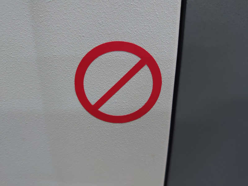
As this had only one part it could be removed just with hands but for a more complex sticker tweezers would come in handy.
Being careful not to touch the sticky side too much I placed it on this surface:
I haven't used this process too much before. After doing this small task myself however I feel much more confident making something with the vinyl cutter should the need arise.
Group assignment
For the group assignment we tested the laser cutters in our Fab Lab.
First we did a test varying the focus height.
I had thought that having the focus offset to either direction would be the same. But because the focus is zeroed at the surface of the material going higher will affect the cutting more. I drew a figure explaining this which can be found from the group assignment. One could think from the results that it's better to have the focus little bit below rather than even slightly above.
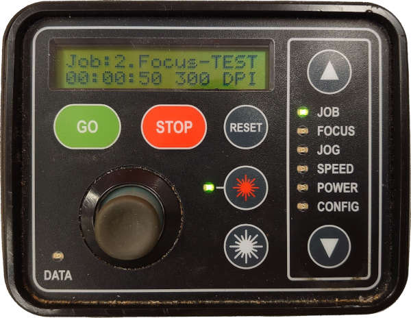
Then we tested some rastering options, like power speed and dpi (Dots Per 25.4 mm). From those I don't have much to say. Less speed, more power and higher density leads to darker engraving. Too much at once leads to burning. If you want deeper then more passes would be the way to go.
Lastly we did some kerf tests. As Neil said the right amount of kerf compensation needs to be accurate down to a few thousands of an 25.4 mm. That would be 0.0254 mm and usually the value ranges from 0.15 mm to 0.20 mm. Generally for the materials I use (4 mm plywood) I tend to use something like 0.17 mm. A good reminder to check the kerf for the material before doing big things… I have had some larger cuts almost fail because I didn't bother to adjust the kerf compensation..
Also the chamfered slot pieces were much easier to fit so I think I will be using those more going forward.
End of week 3.