13. Embedded networking and communications
This week I programmed two Seeed XIAO microcontrollers to communicate with each other using SoftwareSerial library.
Group work
For the group work we programmed two boards to communicate with each other using the same SoftwareSerial library as I would afterwards use for my own assignment.
One of the boards was the one I made and another was Aarne's. Both had the Xiao RP2040 mounted.
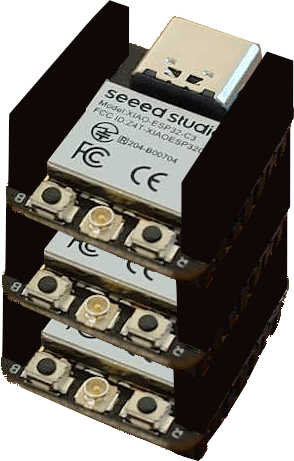
Harnessing the power of modularity
I was thinking if I could use the board I already make at (link previous week). I had the three power pins () pins and three free IO-pins and I was not sure if those are enough for communication. Instantly when our instructor at our local lecture told it’s perfectly ok, I realized that I could take advantage of the different XIAO microcontroller boards having the same pin layouts (which is what I am referring to with "modularity").
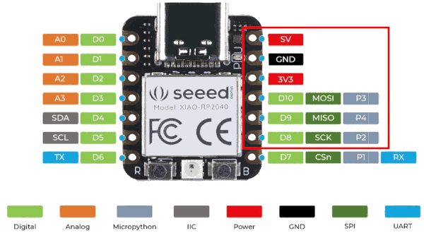
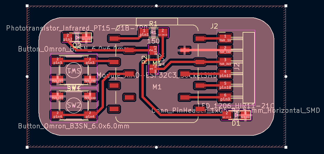
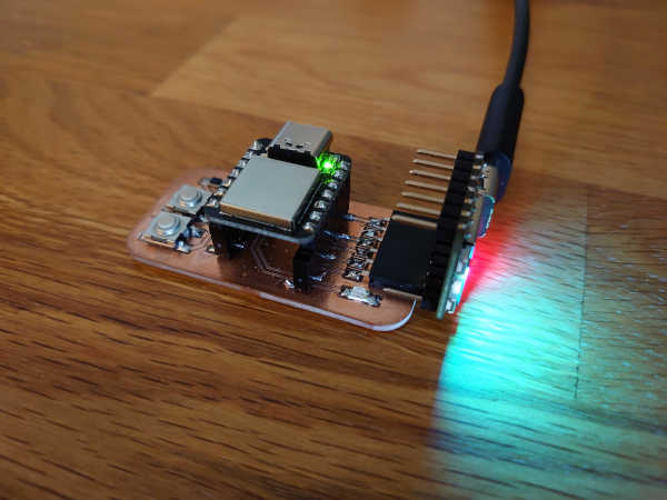
Notice the 6-pins on the right side. In my board I kept the same order for the external pin connectors.
So I can just:
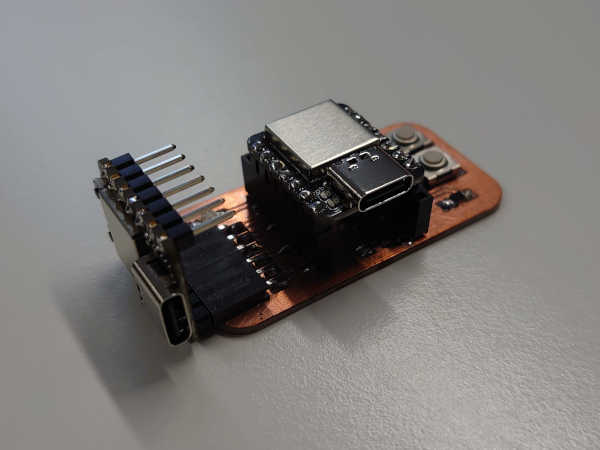
Just... wow...
Well... there is just one possible issue. While the 5V from the USB would provide power to both boards, Also the 3V3 regulators are "fighting" against each other. This might or might not be an issue.
I could not get a confident answer from our instructors or the internet. After some thought I figured that as long as the actual voltages of the 3V3 regulators stay very close to each other there should not be a problem. If one was greater than another there could be current flowing in the wrong direction which I understood many regulators might not handle so well..
At this point in time one could consider measuring the voltages from the regulators from both boards. I went ahead and just plugged it in..
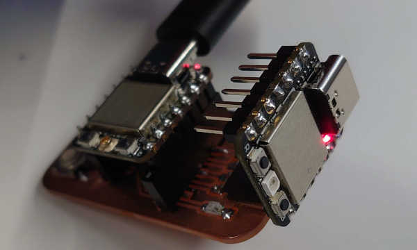
As far as I'm concerned there is no fire or smoke, but instead the powerlights are still on on both boards. So I could assume everything is fine (?..)
Usecase
As I want to keep things simple for this week, I will just try and communicate the pressing of the buttons to the other board which is not connected directly to the buttons.
This is more like a proof-of-concept of how easy it would be to create something more complex while keeping it modular. I am not sure what would be the really relevant application for this.
I heard the ESP32 has a poor ADC. So maybe if you needed that AND wifi/bluetooth capability, you could use the RP2040 to read some analog sensors and the ESP32C3 to connect wirelessly.
However, if you need more pins than the seven (4xGPIO) from that one side, it would be more practical to just go with the “shield” approach. That's where you stack boards vertically with pin connectors.
Though it's still hard to see an actually relevant usecase for multiple stacked microcontrollers.
Programming
So the goal is to communicate the button pressing to the other board which has a built-in NeoPixel. The communication will be done with GPIO pins (General Purpose Input/Output) using the SoftwareSerial library.
The basics of embedded programming were presented earlier in week 4. That page also presents the boards I will be using for this assignment too.
I started with the same code example which we used for the group project. Otherwise the program was made by me.
Here is the unmodified example:
#include <SoftwareSerial.h>
SoftwareSerial mySerial(2, 3); // RX, TX

void setup()
{
  Serial.begin(115200);
  while (!Serial) {
  }

  Serial.println("Goodnight moon!");

  mySerial.begin(9600);
  mySerial.println("Hello, world?");
}

void loop()
{
  if (mySerial.available())
    Serial.write(mySerial.read());
  if (Serial.available())
    mySerial.write(Serial.read());
}
First problem
The ESP32C3 apparently does not support the SoftwareSerial.
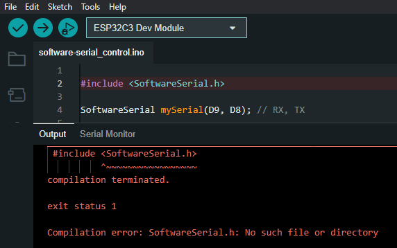
Because when I compiled for the RP2040 OR the SAMD21 both worked. Luckily I had the SAMD21 at hand and could proceed by using that.
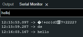
First success
I split the code in two files for the "Control" board which reads the buttons and the other "Peripheral" board which has the LED (NeoPixel). At first I modified those so that the peripheral just sends back all the received messages.
Below are the program codes for each.
This is for the "Control" board, where only the pins had been changed:
#include <SoftwareSerial.h>
SoftwareSerial mySerial(D9, D8); // RX, TX //The correct pins for my board

void setup()
{
  Serial.begin(115200);
  while (!Serial) {
  }

  Serial.println("Goodnight moon2222!");

  mySerial.begin(9600);
  mySerial.println("Hello, world2222?");
}

void loop()
{
  if (mySerial.available())
    Serial.write(mySerial.read());
  if (Serial.available())
    mySerial.write(Serial.read());
}
And this is for the "peripheral" board
#include <SoftwareSerial.h>
SoftwareSerial mySerial(D8, D9); // RX, TX // Notice these are opposite

void setup()
{
  Serial.begin(115200);

  Serial.println("Goodnight moon2222!");

  mySerial.begin(9600);
  mySerial.println("Hello, world2222?");
}

void loop()
{
  // For now, just make it return what is received
  if (mySerial.available())
    mySerial.write(mySerial.read());
}
Result
Again, the code is split to two files:
Which are also embedded and explaned more below in the next section.
Here is the result:
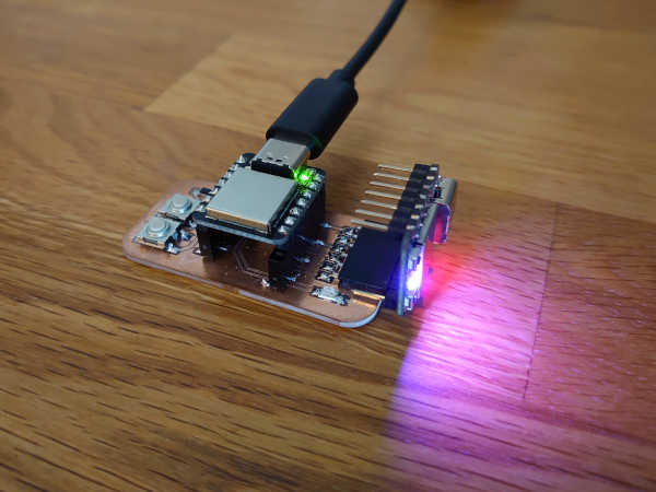
As an animation. Note that the color switches only once for each press of the button. It is hard to see from this gif sadly.
The funny thing is that it can also be powered from the other board's USB port.
Control
This program reads the button presses and sends commands to the other board accordingly. The commands are singular characters or integers.
The first button turns the led on/off by the messages 'o' and 'f' correspondingly.
The second button iterates through a set number of values (integers, here 0 to 5).
Peripheral
This program is for the RP2040 as it has the built-in NeoPixel. It reads the commands sent by the other board and using a switch-case structure acts accordingly.
Note that here the "animation state" is only a specific color. It could be something more sophisticated too.
Additionally the state is kept while the led is turned off.
Note on the after additions
Notice the added networking addresses. These were added later to comply with the networking requirement. Now the boards know the sender and recipient of a message. The message format is now:
(recipient)(sender)(command)(line-ending)
The parsing is quite primitive and assumes only one digit for each field. I have highlighted some of the more important lines regarding the addresses.
To make these changes I had to make fundamental changes to the code and the whole message format. Of course this is a small project but still took a moment to figure out. In the end was able to get it working exactly as presented above.
End of week 13