5. 3D scanning and printing
Group work
In the group work we printed some test models found from the internet with different printers and compared the results.
When it comes to the most common type of printers, FDM (fused deposition modeling), I have learned that more expensive is not always better. While we have some really expensive ones that do have some nice features like two extruders very frequently they need maintenance and are thus unavailable.
Whereas the cheaper machines like the Ender 3 (<300€), when tuned correctly, seem to be reliable and produce great print quality. Of course they have limitations like print material but I have yet to see a need for anything other than PLA. Another downside is that usually those cheaper machines cannot be left unsupervised. This means no overnight printings which can be a scheduling issue.
I believe the main selling point to be that you can make more complex shapes when the support is different material and can even be disolvable. However I prefer to design the models I 3D print from the start to be easily printable.
When you need more uniform parts with very fine resolution the Formlabs is the way to go. It is an SLA (stereolithography) printer where liquid resin is used to form the model. While it can achieve very fine quality the gooey (toxic) resin freaks me out... They say it's "similar or safer than other household chemicals". My concern is that people touch surfaces with that they shouldn't with the contaminated gloves and then it gets to your skin.
I tend to prefer safer non-toxic materials like PLA.
3D scanning
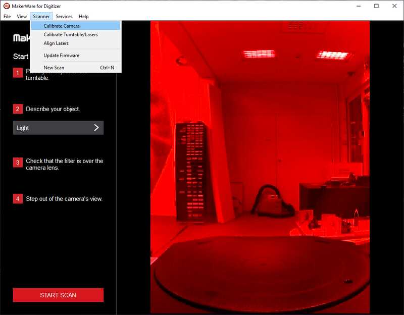
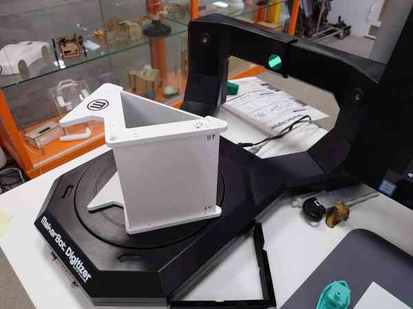
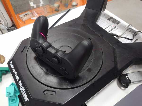
I used the MakerBot Digitizer in our lab. It projects a laser line on the object and uses a camera to analyse the surface. It rotates the object to get a 360° view.
To operate the scanner I used MakerWare for Digitizer The software is said to produce "watertight" models which means the surface is closed. That seems promising.
Calibration
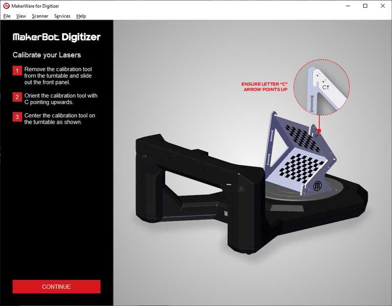
First I went through the calibration procedure. The software had very clear instructions which the following images show.
This is where I began the calibration:
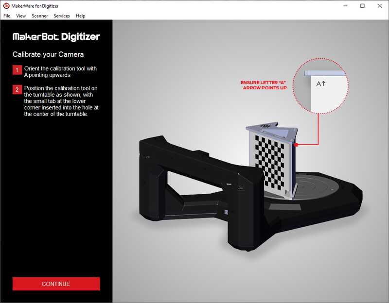
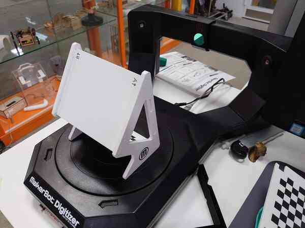
Step 1.
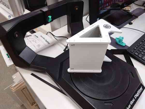
Step 2.
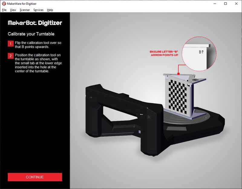
Step 3.
And done.
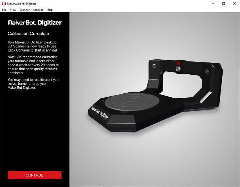
As it says there its recommended to do this calibration quite frequently.
Scanning procedure
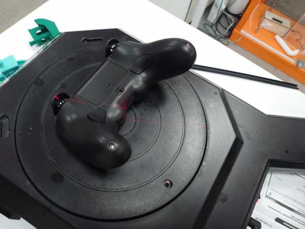
Then I was ready to scan my object. I wanted to scan a gaming controller and use the scan to 3D print a stand for the controller.
Object placement
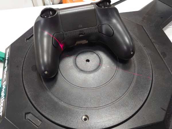
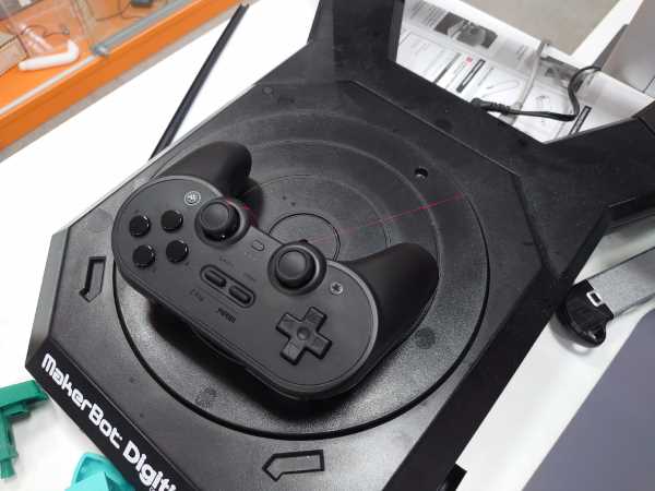
I did multiple scans (explained later) and changed the position and orientation of the object for each scan. As the lasers point directly to the center I figured that you want to place the parts that you want to focus on so that the lasers hit it the most.
Below are some of the positions and orientations I used when scanning. For example, in the first image I placed the joystick to the center as that is a key part when making the stand.
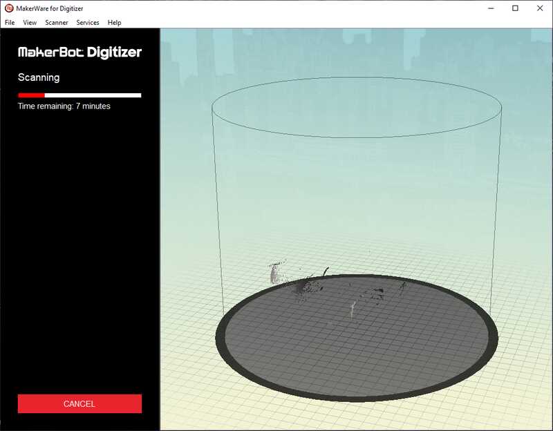
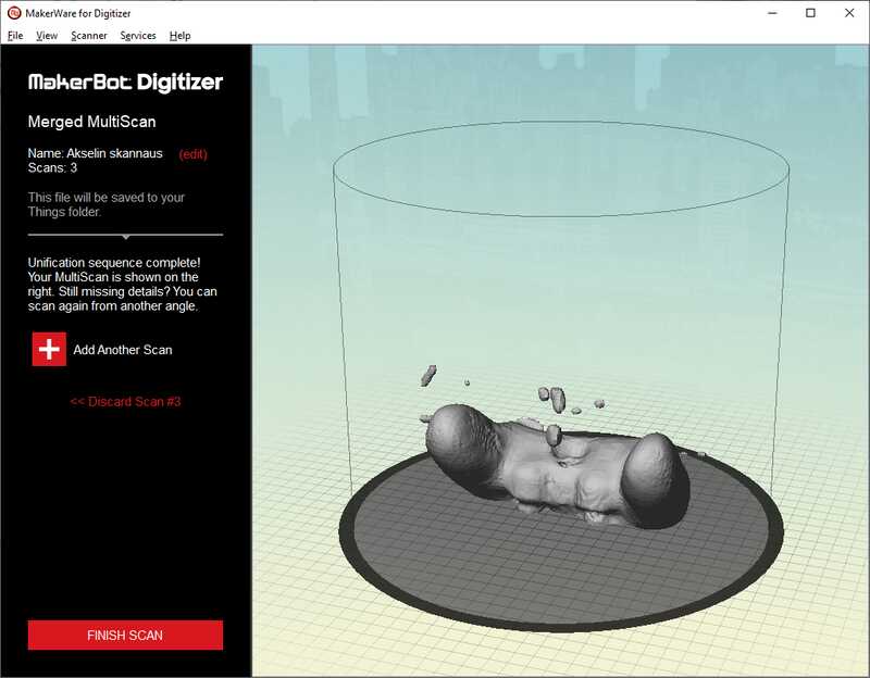
Scanner software view
On the left you can see the beginning of the scan and on the right the first scan completed.
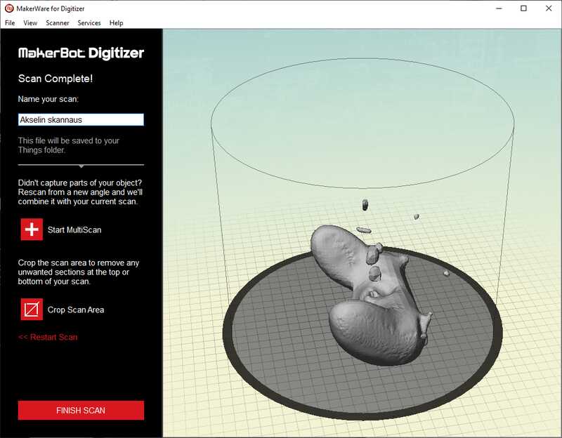
I then pressed the Start Multiscan to enhance the accuracy and details.
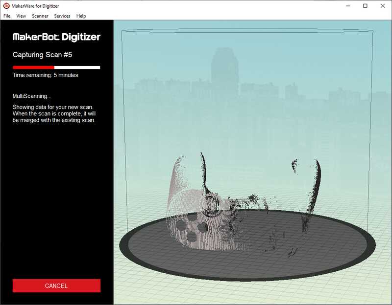
Here on the left you can see how the scan picked up one of the joysticks which was in the middle of the scan area. On the right I did the same for the other joystick.
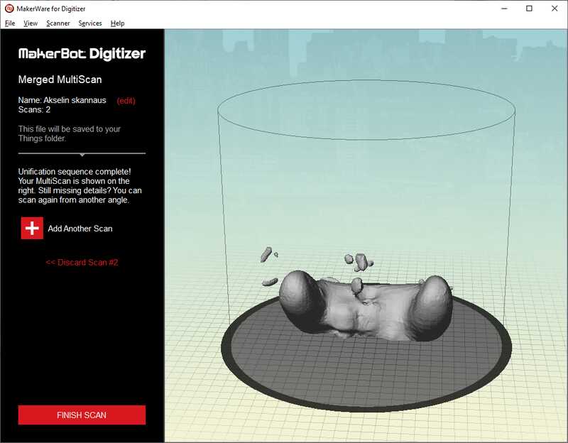
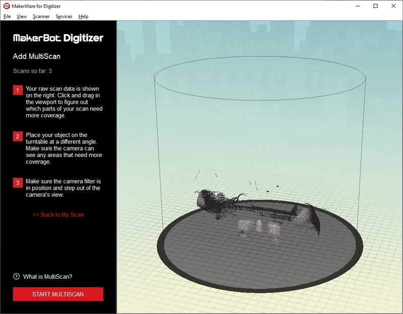
And further scans:
Result:
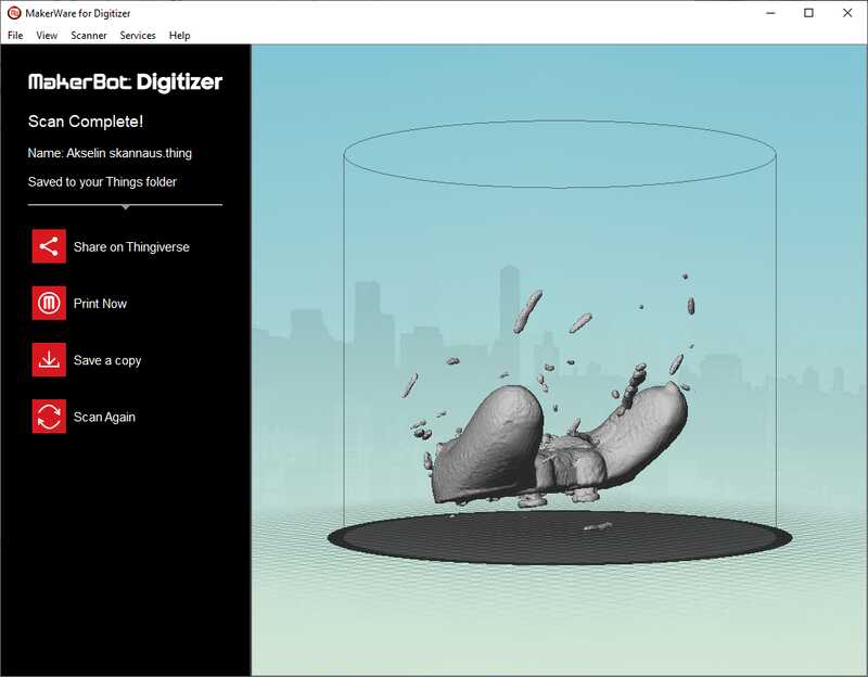
The raw mesh is way too big to upload here. So I only uploaded the simplified files under source files
Post processing the mesh
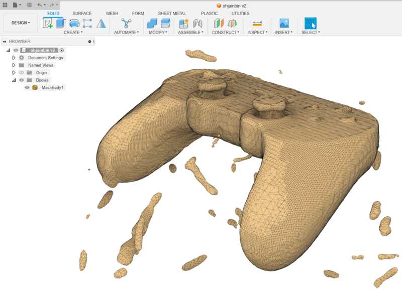
As the mesh is quite messy straight from the scanner, it will need some post processing. I used the mesh workspace in Fusion 360 as I belief that to be sufficient for my needs.
Here is the raw mesh just imported to fusion. (I only changed the color)
Separating the noise
I used the Separate tool under Modify to get rid of the floating extra pieces.
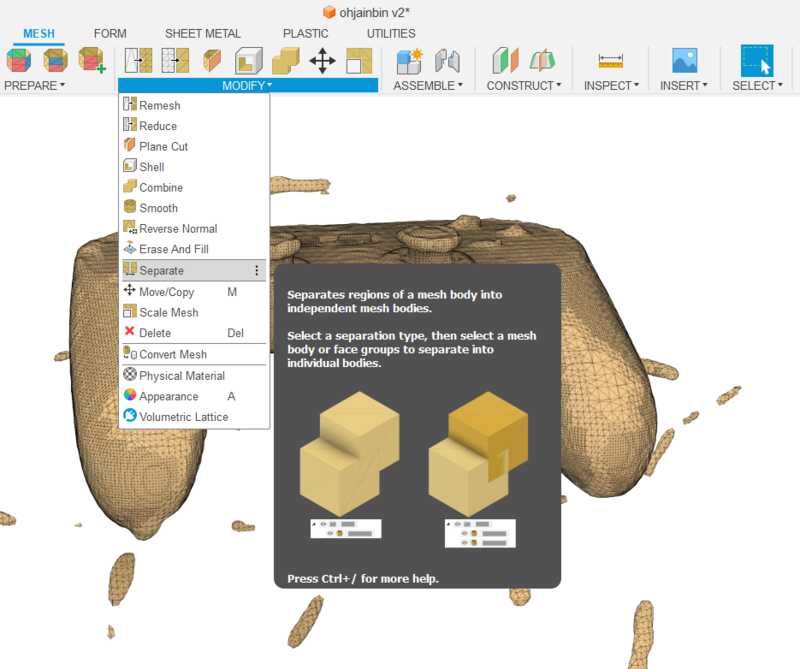
I selected the body and used the default settings.
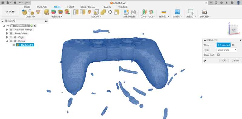
The result was 60 separate mesh bodies and therefore there was 59 unwanted bodies from noise.
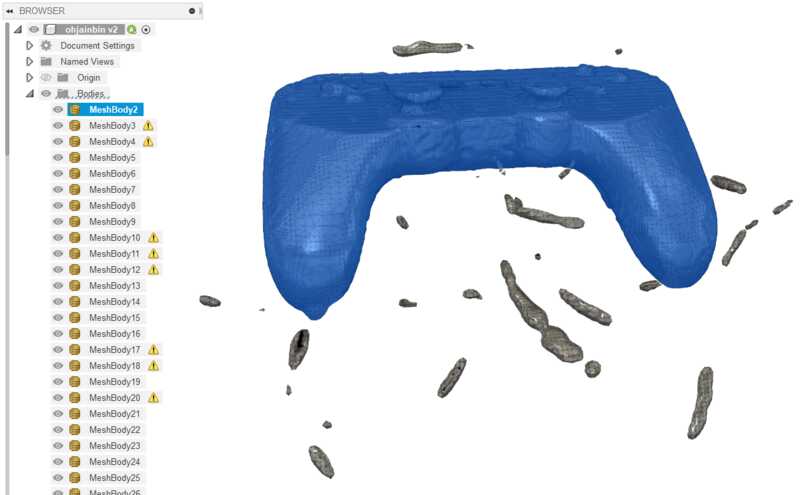
I then deleted only but the first mesh body.
Simplifying the mesh
The mesh was still way too complex and would need to be simplified.
I used the Reduce tool:

I chose the Tolerance type with a value of 0.2mm.
(I had already scaled the mesh. For this I didn't need much accuracy)
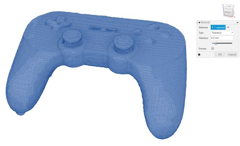
Here you can see the, atleast slightly, simpler mesh:
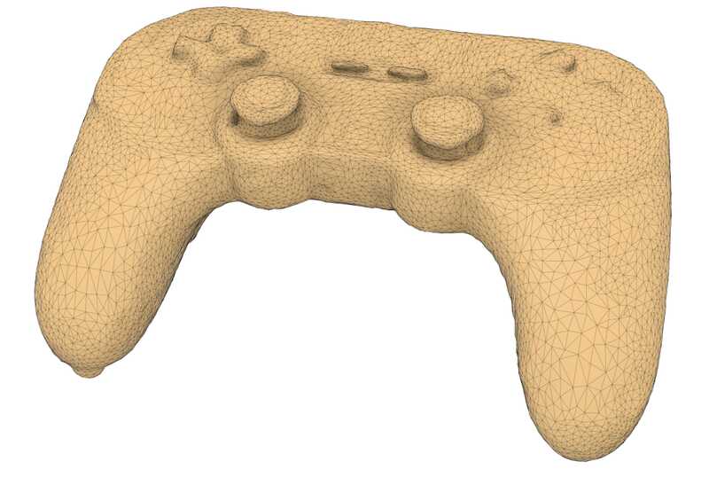
Cutting the mesh
The mesh still had a lot of triangles (too much). As I was going to use only a part of the mesh to model a stand for it, it would make sense to cut the mesh and keep only those areas that I need.
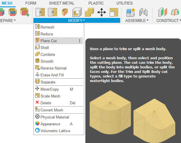
I used the Plane cut tool to achieve this:
With several cuts I reduced the mesh to what was needed. You will see the result in the next section.
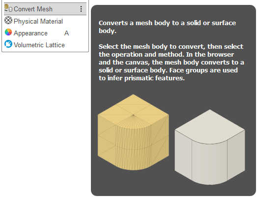
Converting to a body
To use this mesh in modeling I think it's necessary to convert it to a body.
This was achieved simply with this tool under the Modify tab:
Regardless of the mesh having much less triangles I still got this warning:
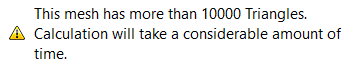
I still went ahead and the processing really did take a while. The result turned out fine though:
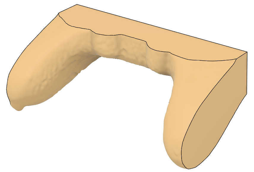
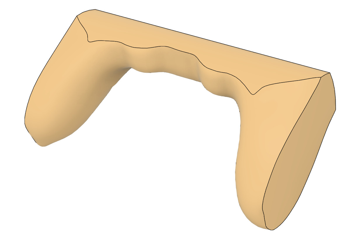
Resulting stand
I then used the body to cut the shape out of a box with the boolean operation. Here is the resulting stand:
As you can see it's quite bumpy. I did try smoothing the mesh but that seemed like even slight smoothing would lose the important shapes and the controller wouldn't fit.
It would be possible to print that but it would likely look horrible. So I will not print this one. I'm sure there is a way to improve that model though...
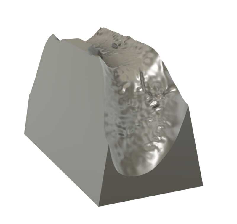
Smoothing (post addition)
I later realized that I just had to use low enough value for the smoothing. And thats what I used on the part I uploaded to source files. Additional reason is that the file size is much smaller with the smoother surfaces.
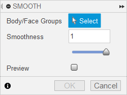
The smoothing is found here:
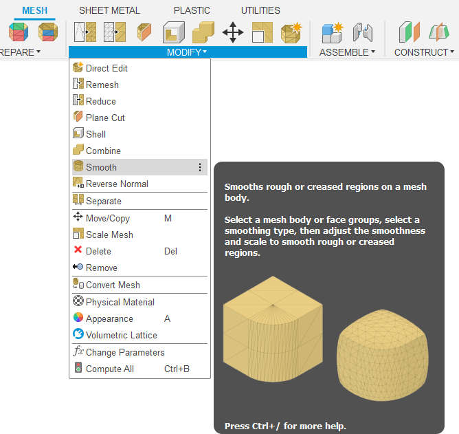
I used 0.15 as the value and that I think was a good balance.
And it resulted in a much less eye-damaging view:
Regardless, I will design a different product for the printing.
3D printing
For this task I really wanted to design something actually useful. A ball inside a cube isn't going to cut it.
I had couple of ideas but finally had a realization on how I could fix a long time issue with cable management.
I have these usb cables (for phone etc.) on my table that I would like to be minimally visible but still accessible. So some kind of a cable holder would be needed.
It would, of course, need to be complex enough to meet the requirements of this assignment.
Modeling
Here is a first quick draft of what the product could look like and how I could make the slots.
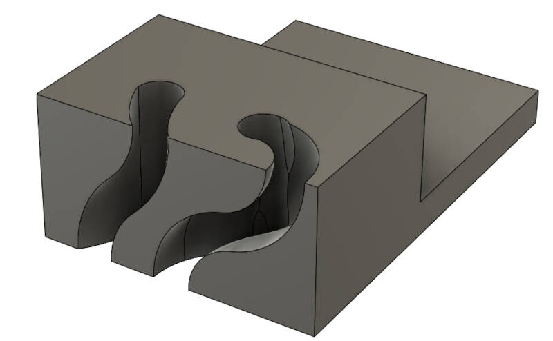
So the realization was to use Loft to make these slots.
It's useful when you have a shape that changes gradually to another shape.
Here I have the top and bottom profiles and some guidelines. This makes the whole slot shape.
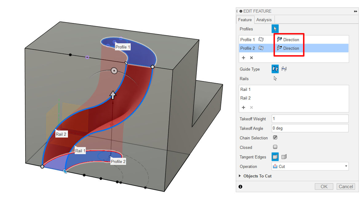
Then it's just a matter of replicating and some filleting.
Here is the finished model:
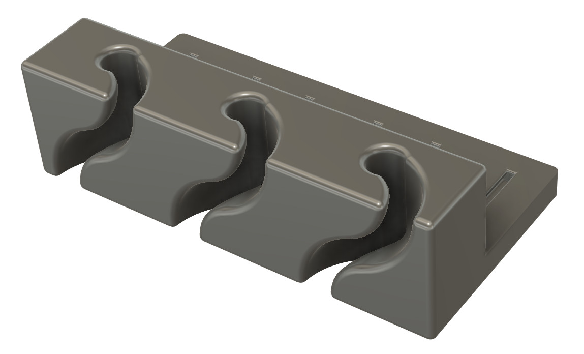
Those curved slots, while theoretically could be made with 5 axis milling, I would count as not being "easily" done that way.
The main intention is to install the cable holder with (a) screw(s). Just to be sure that it meets the requirements, I added these slots that would help bonding when installing it for example with hot glue instead of screws.
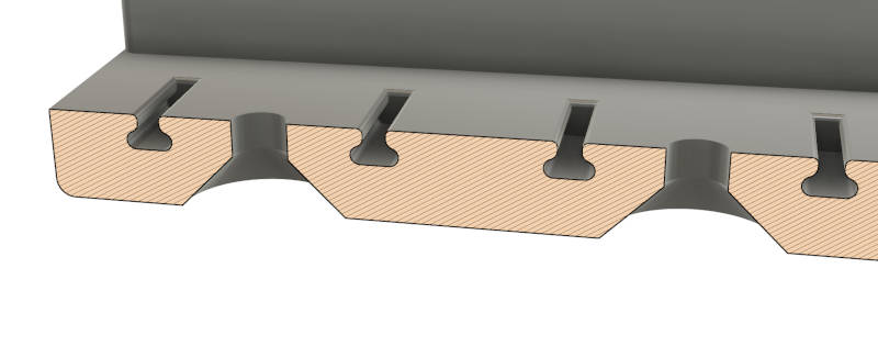
At first it seems that that "T" shape could be manufactured using an undercut end mill. However, the dimensions of the slots make it impossible for a wide enough tip to not to hit the openings of the slots.
Exporting as STL
To print a 3D model it is commonly exported as STL file.
STL is a mesh file that represents the 3D model with points and triangles.
Coincidentally, the 3D scan was also exported as an STL file.
In fusion 360 you can just save a body as mesh. It gives you some settings to tweak how accurate the STL should be. Increasing the accuracy increases the file size.
Better way would be to export as a STEP file but that is not yet supported by most slicers.
Little bit more about that at the end where also the source files are.
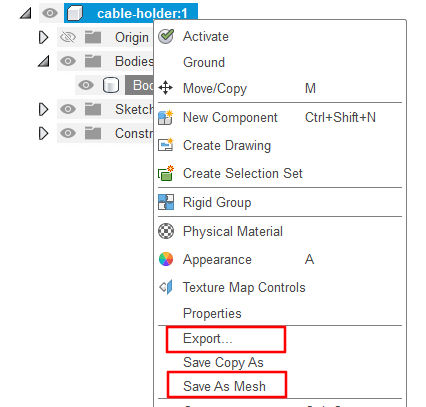
For both methods you would right click the component and select which you want.
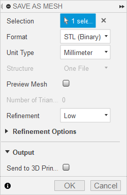
Here are the possible parameters for "save as mesh"
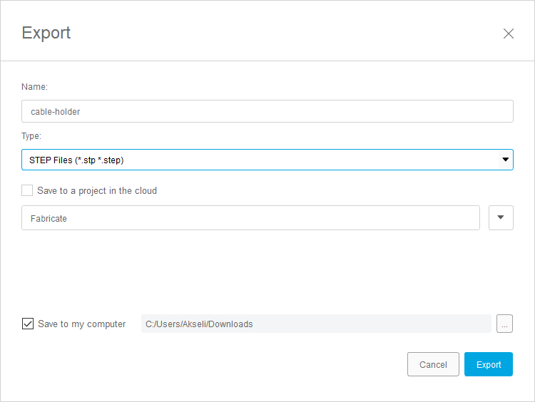
And same for "Export..."
which also has more file types like the fusion 360 archive file .f3d.
When exporting to a STEP file you lose the history
but keep the actual shapes like curved surfaces etc.
Slicing the STL
To actually print the model it needs to be "sliced". It usually means slicing the 3D model to 2D layers which are then converted to G-code that the 3D printer understands. For this I used Ultimaker Cura slicer software. Because that works well for the printers that were available at the time.
Here I have imported the STL in to the slicer software.
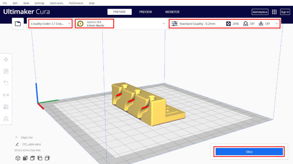
I have highlighted the printing settings that I used. I just had to choose the ender 3 which I was going to use. Otherwise I didn't change any print settings there.
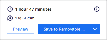
After clicking on Slice it shows an estimate of the print time and amount of material used.
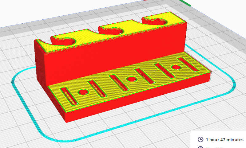
It also shows a preview of the G-code that was generated.
Now the generated G-code file can be transferred to the printer via usb-stick.
Printing procedure
I printed it using the Ender 3 printer. To print I only had to find a MicroSD-usb adaptor to get the file to the MicroSD card that's inserted in the printer. Then it was just a matter of selecting the file and pressing print.
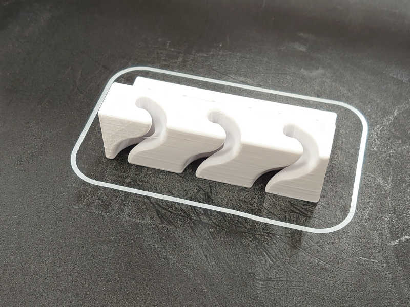
Unlike in our group work prints, this worked out nicely the first time.
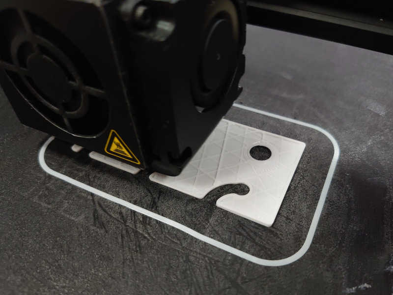
The print stayed on the table.
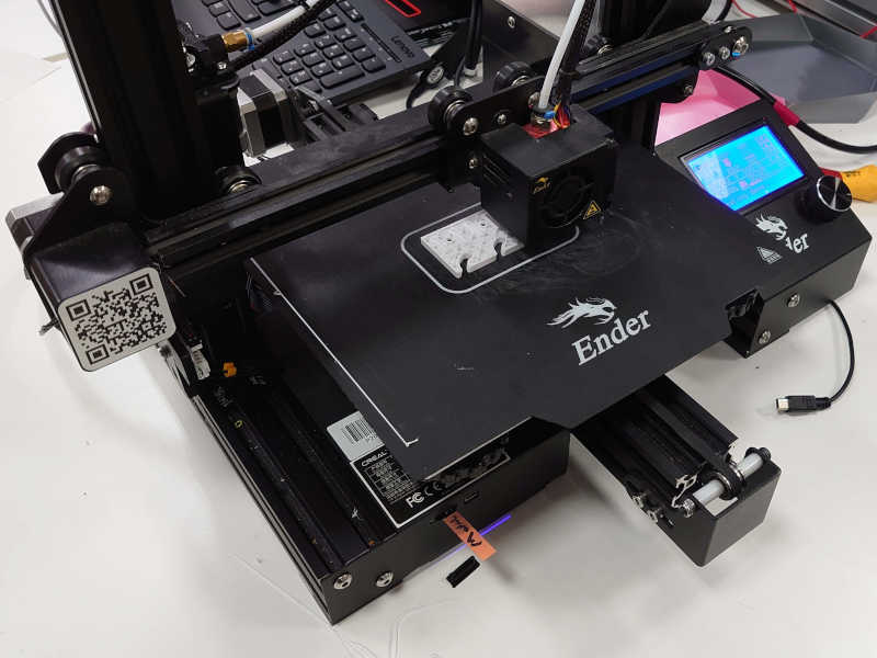
And turned out nice!
I went ahead and installed it to my table with couple screws so it stays.
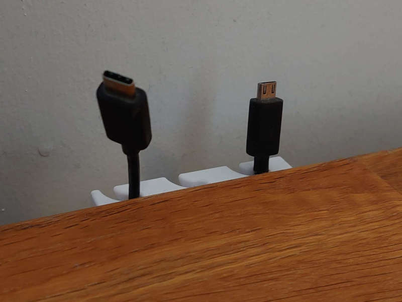
The cable holder worked just as it's supposed to. The cables slide in and out but wont fall from the slots. To add or remove a cable it needs to be slightly bent but not too much so it isn't harmful for the cables.
Source files
-
Post processed scan F360 (455 KB)
-
Post processed scan STL (453 KB)
-
Cable holder F360 (1305 KB)
-
Cable holder STL (547 KB) (low detail)
-
Cable holder STEP (625 KB) ("lossless")
.step files are to .stls like png files are to jpg files
in the sense that those do not lose details.
Therefore it would be better to standardise the use of STEP files in place of STL files.
End of week 5.