2. Computer-Aided Design
This week I made both 2D and 3D designs of my possible final project, doorbell. Here I went with the idea of laser going through the window. This design has the benefit of not being sensitive to the thickness of glass.
2D
First I did both raster and vector illustrations of the idea.
Raster
When I want to get an idea visualized quickly I use either pen & paper or MS Paint.
This is the fastest way to get something that you can explain an idea with. It is crude but also efficient. There is no separate source file as its just a .png to which I drew lines and rectangles.
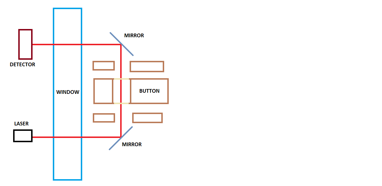
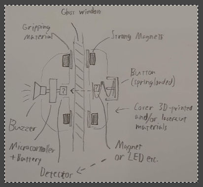
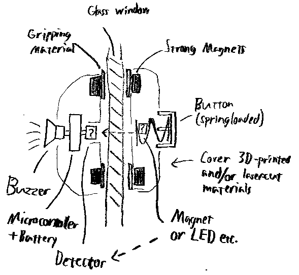
This is a new idea for the doorbell final project. What if the detection was done with laser and a button would block it's path. When the button is pressed the holes align and the laser is let through. Benefit of this design would be that the thickness of the glass wouldn't matter. However the laser needs to go through the glass, which I think IR laser would not do. Have to figure that out.
 (Right-click to download source png)
Vector
Here I went with Inkscape. I think vector graphics is powerful for digital art and for me all my files for lasercutting go through Inkscape. However, I would pass this step when designing myself. As in straight to 3D after the possible quick paper/raster sketches. Inkscape is more powerful for other things, but for design (that's not directly for a machine) you could compare it to any office programs like Google Slides. What I mean is you can put shapes, text and color stuff, and later move things around, which is great when building an idea collaboratively. Though sometimes it might be useful even when designing alone, as you can change the design more flexibly.
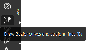
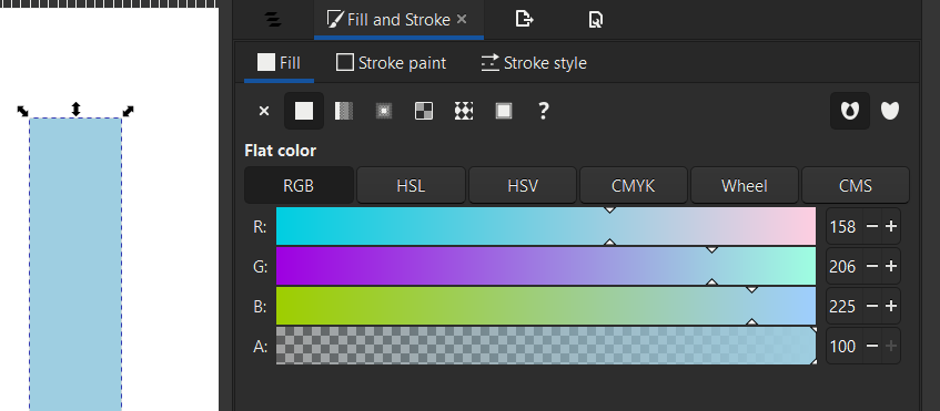
I drew simple lines with the bezier tool by holding ctrl while drawing and also rectangles. I used fill & stroke to color those.
Fill and stroke can be found from the object menu. It allows precise control of colors and line thichness.
.svg files are also neat because those can be emdedded directly to a website.
For the original file you can right-click and save image as.
Here I duplicated the drawing to illustrate functionality:

Drawing in 2D did help to advance the idea, have to give it that. Next some actual CAD design..
Paper drawing to digital
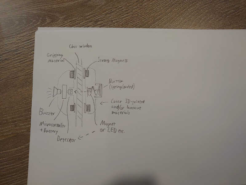
As an additional experiment, I wanted to convert an image of a paper sketch to a more suitable digital illustration.
Here is the original paper sketch (resized and compressed only)
I opened it in GIMP.
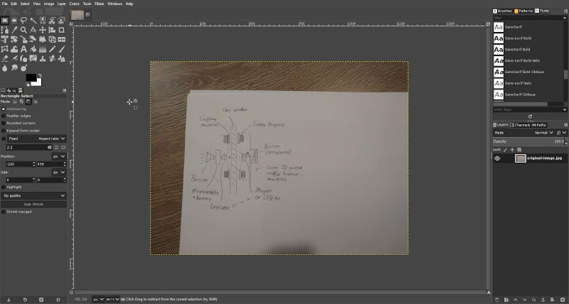
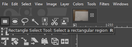
Using the rectangle tool I cropped the sketch.
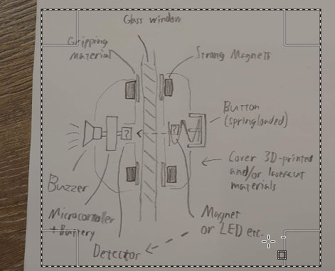
Like this.
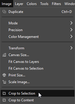
And from the Image menu Crop to selection.
Results this.
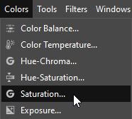
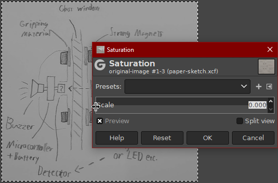
For the next step to work I first have to desaturate the image. An organic image always has some color from the lighting etc. So Colors > Saturation...
Dragging it all the way to zero.
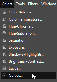
Next I can make the image almost monochrome by adjusting the curves. Colors > Curves...
Notice on the background there is a faint histrogram of the image.
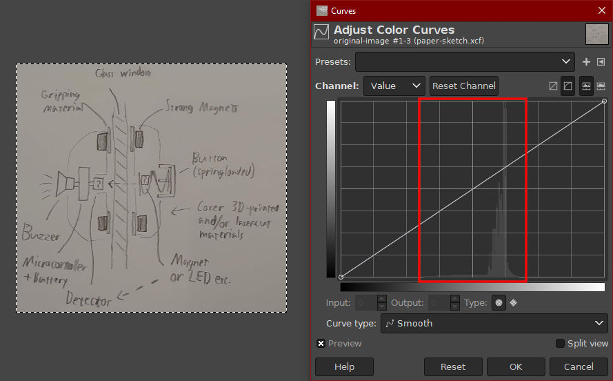
Using this as a reference I drag the line to create control points like this.
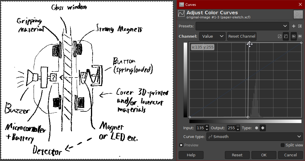
Adjusting those changes how sharp the image looks. I left it as this almost pure black and white.
To export as png go to the export menu.
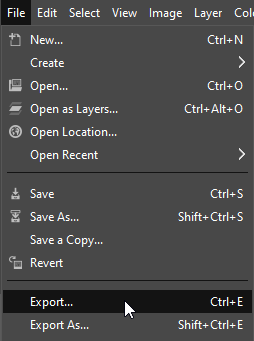
And name the file extension as .png, the other options I left as default.
Here is the result:
This could be used for example pre processing for an image to then be loaded into inkscape and traced for laser cutting. Many Fab Academy students have done the Trace to bitmap so I thought this would be a helpful addition for anyone going that route with anything other than already pure black and white images.
Here is the GIMP source file
3D
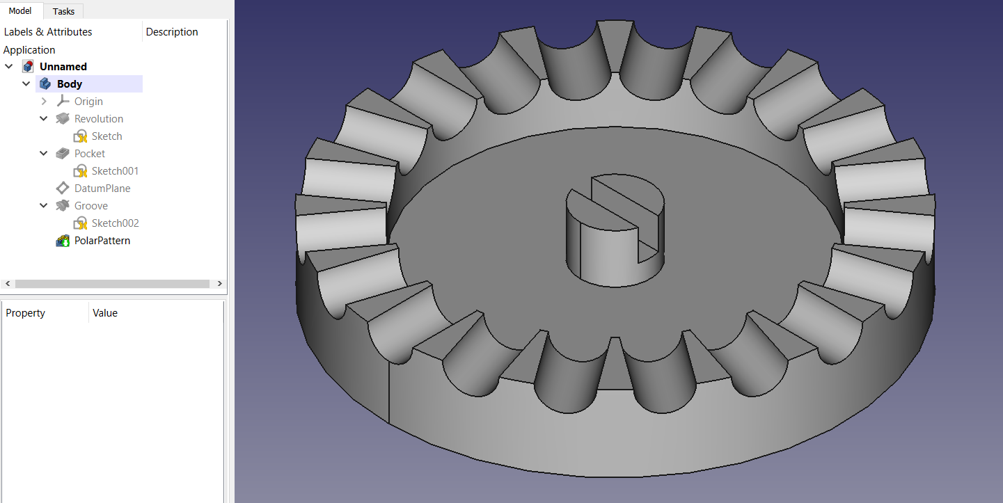
Here I used Fusion 360. I have gotten used to it but due to the licencing and some ideological reasons I would have wanted to learn Freecad for this assignment. In the last global lecture I was amazed that Freecad actually has almost all the features I use in Fusion. So during the local lecture, as I have tried a couple times before, I opened Freecad and started to design something. I could manage to do the basic things, but for every step I had to figure out where and how it's done in Freecad. This is just an example of what I did in freecad.
In the end I scrapped the idea and decided to go with Fusion 360 for now as I don't have the time and dedication to learn Freecad. It just feels so different and complicated compared to Fusion. I still hope that when I am no longer a student I would be "forced" to learn Freecad.
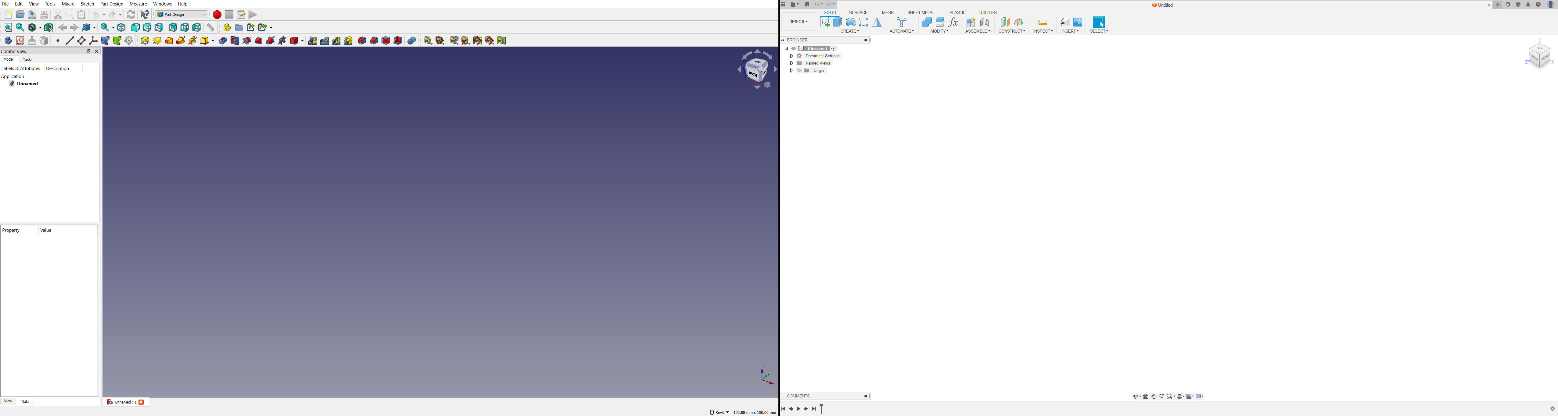
Here are Freecad and Fusion360 UI's side-by-side:
Basics of 3D modeling
In 3D design you could start with combining primitives like cubes and balls but usually for anything relevant you start with 2D sketch. Then that 2D sketch can be brought to 3D in several ways of which extrude is probably the most intuitive and common. The way used depends on the shape that is being designed.
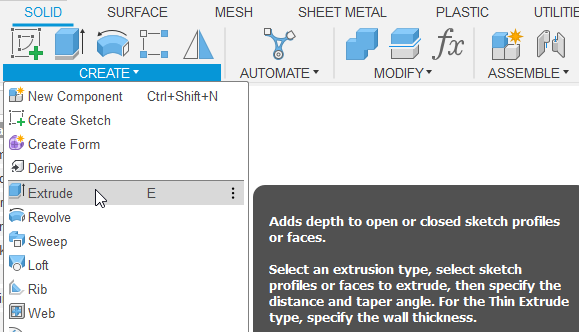
Extruding and revolving
The first way to make the 2D sketch into a solid 3D shape is to extrude it linearly.
In Fusion the shortcut is E.
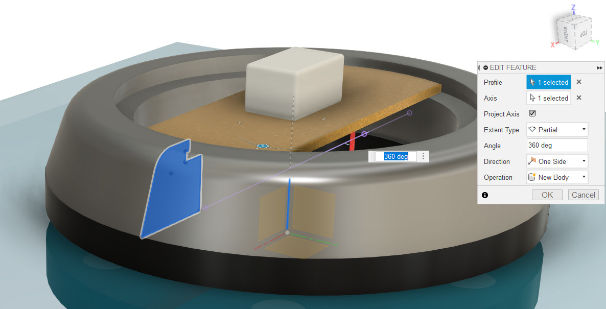
Another way is to revolve the 2D profile around an axis. The axis has to be paraller to the sketch profile. This is useful for objects that have some level of radial symmetry.
Constraints
The one thing that makes CAD really powerful is the ability to add constraints to a drawing/sketch. This effectively makes the drawing "smart".
There are two types: geometric and dimensional constraints. When a geometry is fully constrained you can control it by changing the dimensions.
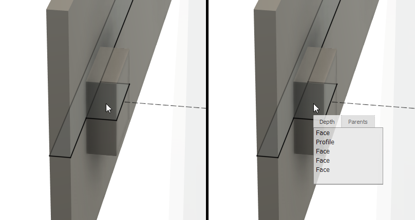
Tip: List possible selections
This tip was mentioned during the local lecture. It goes in to the category I wish I knew this from the start. Let's say you want to select something that is obstructed like the profile sketch in the below image. Before knowing this I would first hide the body with V and then make it visibile again after.
But if you click & hold left mouse button a list will show the possible selections. It will also highlight the object when you hover over the list item. For example below I just need to select that "profile" item.
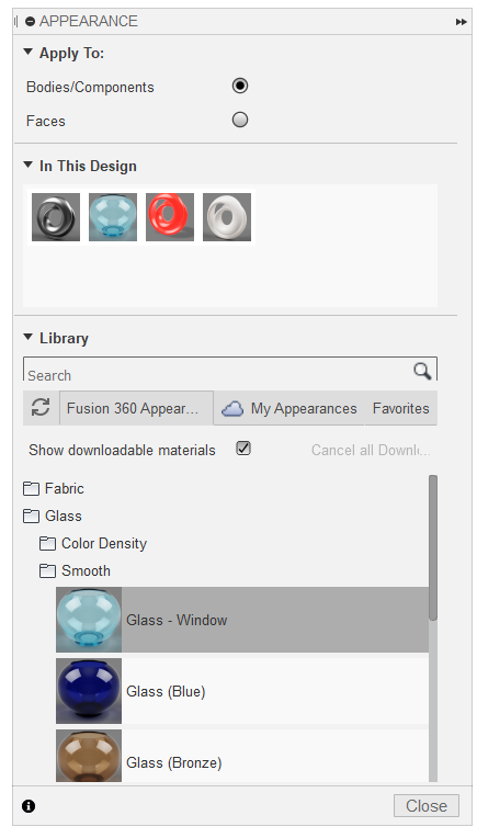
Appearances
For added visual effect I put some textures to the parts. This can be done with the appearances menu that opens by pressing A.
Step-by-step of my 3D design
I added this section to go into further detail according to the evaluation feedback. I will try and elaborate on the steps I took on my 3D design process but I will still assume some familiarity with Fusion 360. Also I will try to not repeat too much of the concepts explained elsewhere in this page. For example the very basic principles of CAD presented earlier.
I have already created a new file, remember to save often.
First step I usually do is to create a new sub component.

It can be named on the prompt or renamed later.
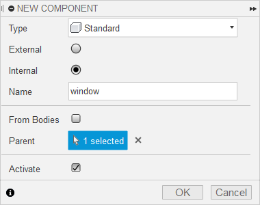
This will make it easier to manage parts of the design. Also I usually start with a component named "draft" or "demo" that I can just start designing on quickly. Then I get a better idea on how I should structure the design and, if needed, I can just delete this initial draft.
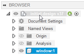
For this design, I already had the idea of how this design should be structured. I have three main components, window, the inner and the outer parts. Those can have additional sub-components later.
Next I would create a sketch that will create the "Window".

Select a plane for the 2D sketch.
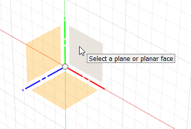
For this the Center rectangle is the easiest.

Click on the center of the sketch first.

Then, by pressing D for dimension, I can define the width of the rectangle.
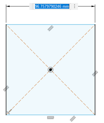
This window is just an arbitrary example of a glass surface
to which this device would be mounted. I set the width to be 200 mm.
To make this a square, I will select two sides and apply the Equal constraint.
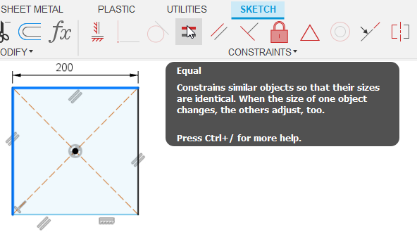
After that click on the green finish sketch icon and
then use the Extrude command or press the shortcut E.
Sometimes the extrude tool preselects the last shape you drew but if not click on the square.

I set the thickness to 8 mm. For this piece it doesn't really matter.
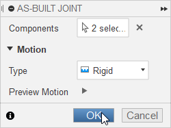
The "window" component is now ready. I will constrain the component using As-Built Joint so it cannot be moved accidentally.
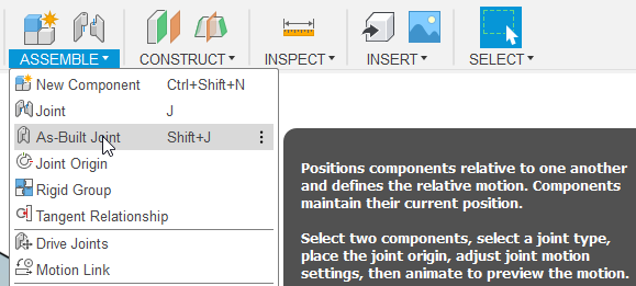
Select the "window" and the root component. Make sure the joint type is Rigid.
Then I created a new component. Remember to activate the component you want to work on by clicking the circle icon next ot it.
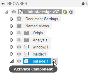
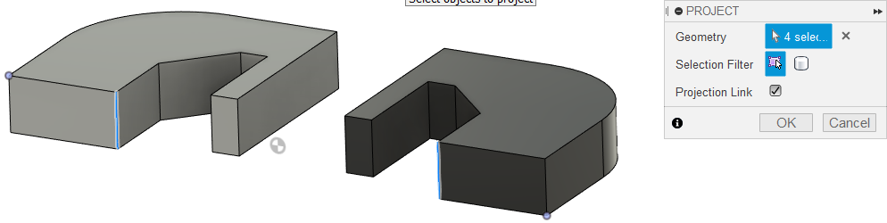
I then created a new sketch under the "outside" component. I will project the previously created "window" to this sketch using the Project tool.
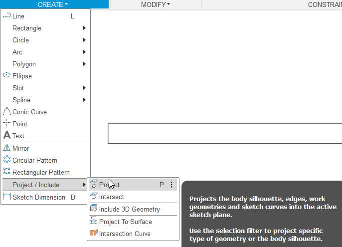
This will project the selected shapes. I selected the top of the window square.

And it looks like this.

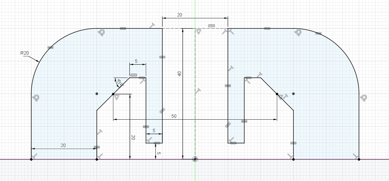
Next I will create the shape using the Line tool
(shortcut L).
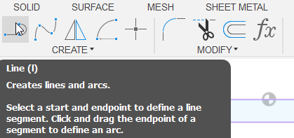
Click and drag to draw lines.
I will first just draw the shape and ignore the dimensions.
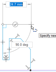
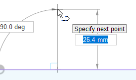
With the same line tool, clicking and holding from the end of the last line I can create arches too.
This arc will automatically be tangent to the initial line.
But for the continuing line I will have to use the Tangent constraint. I will first select the line and the arch and then apply the constraint.

For these lines I applied the MidPoint constraint.
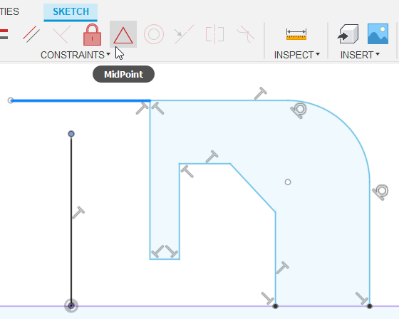
By pressing the shortcut X the selected lines or other objects
toggle from normal to Construction lines.
These lines help to constrain the sketch
but those won't define the borders of extrusions, for example.
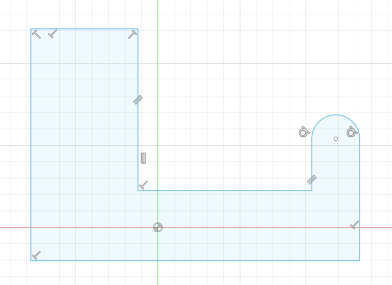
Only the parts tinted blue can be extruded.
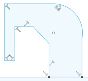
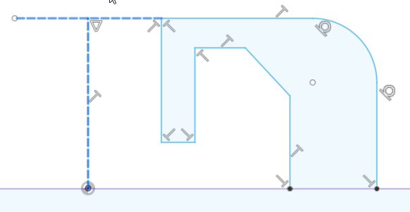
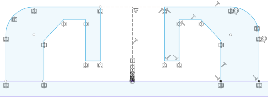
Then I mirrored the shape using the Mirror tool.
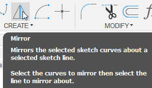
Tip: Double clicking on a line will select the whole shape.
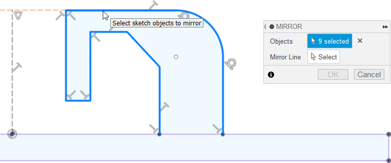
Then I just select the mirror line.
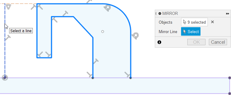
And it mirrors the shape. The sides are now linked so moving one moves the other.
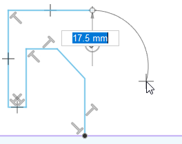
Then I used the dimension tool again to apply dimensions.
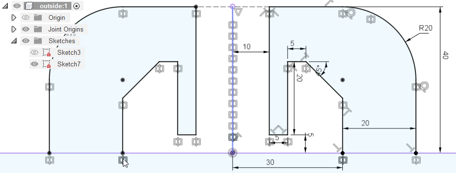
You can see the lock icon on the sketch icon on the left. Also all of the lines are now black. This indicates the sketch is now fully constrained. You should almost always strive to fully constrain any sketch.
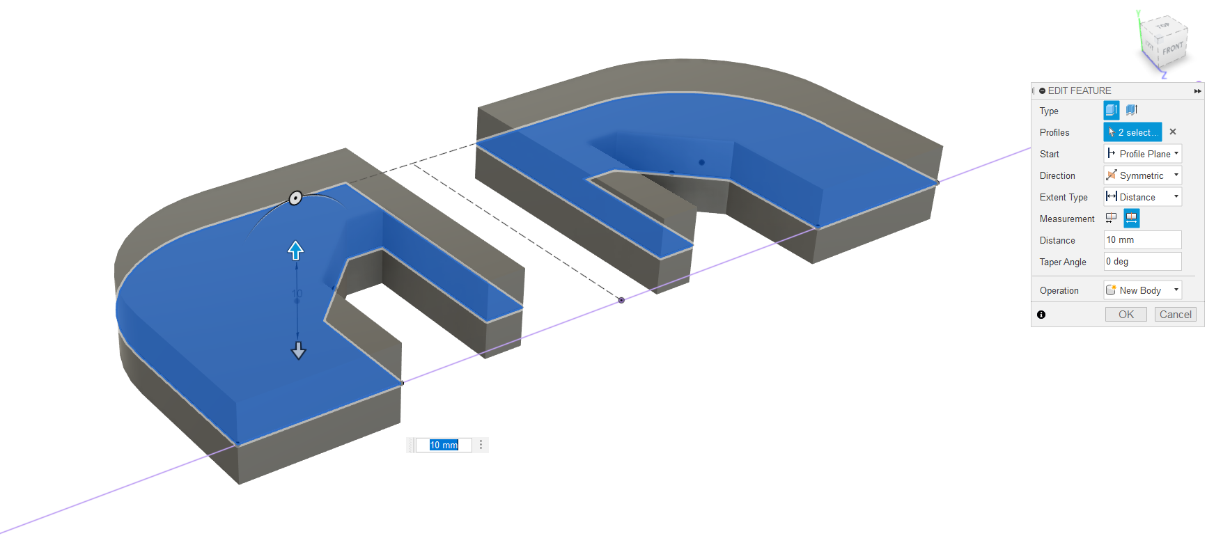
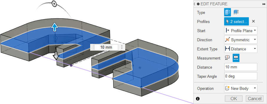
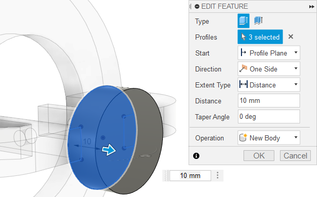
Then I could extrude the shape.
Holding Ctrl allows selecting multiple shapes to extrude with one operation.
Then I created a new sketch. This time I selected a surface on the model as the sketch plane.
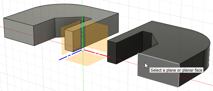
Then projected parts of the previous extrusion.
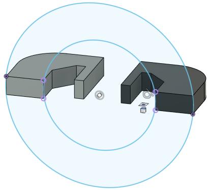
Using the 2-Point Circle will make easy constraints here.

By default, Fusion 360 will automatically want to create some constraints. This middle constraint is one of those cases.
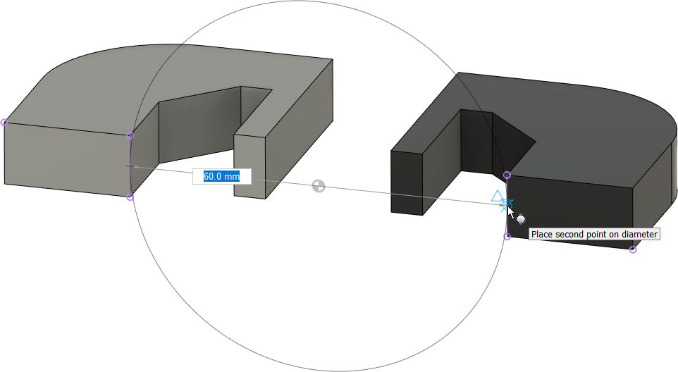
Here I didn't fully constrain the circles but it's fine for now.
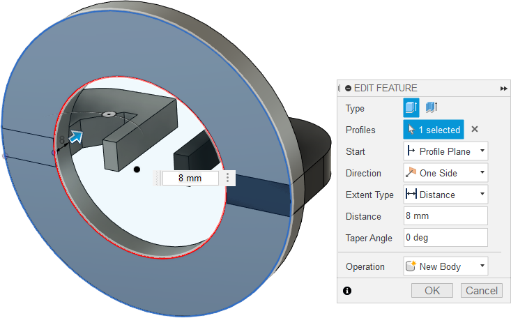
Then I extruded the ring shape. I changed the operation to Join.
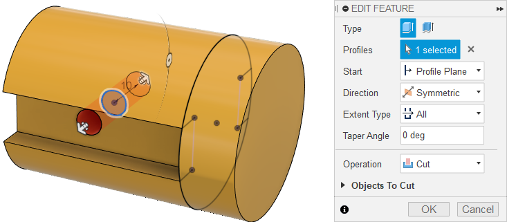
Then I created made a hole on the modle by extruding a circle and using the Cut operation.
I then created a new component "button" and made the shape as previously.
Second extrusion joins only to the body of the same component.

Using the same circle from the previous hole I cut a new hole in the button.
And a space for the spring.

Under the create menu I used the Spring tool to create a resemblation of a spring.
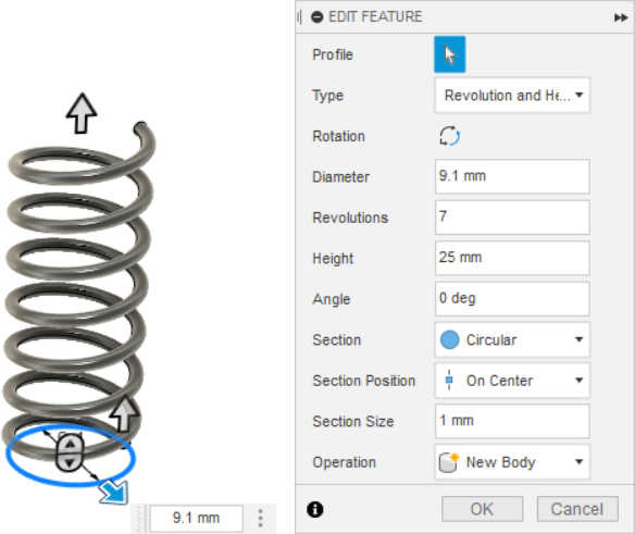
There are many parameters for the spring but I just wanted something to show there would be a spring so it wasn't particularly accurate.
I also made the other side of the design in a similar way.
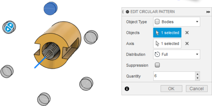
After that I made simple cylindrical magnets. I have six of those so the Circular Pattern is perfect here.

Selecting the bodies and the middle axis will duplicate the magnets.
Those were then cut from the main body to create holes for the magnets.
To add further detail just for nicer looks, I filleted the magnets.

I also did this for various parts in the model as the last finishing step.
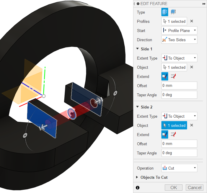
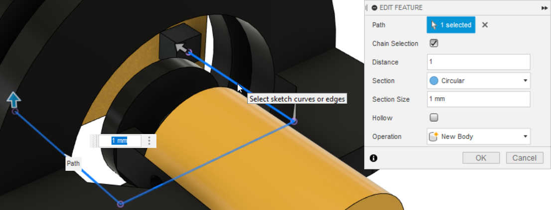
To visualize the laser I drew this line going from the laser to the detector and reflecting from the mirror surfaces.

Then using the Pipe tool I created a solid shape following the line.
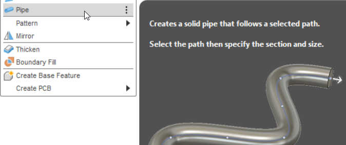
Like this.
The result can be seen at the end of the page
Video of the design process
This video was recorded with OBS studio and compressed with VLC which uses FFMPEG under the hood. It shows the design timeline which means every stage/feature is one step in the video.
Converting the video with VLC
I didn't know VLC had this feature until a friend told me. You can use it to convert/compress videos in a rather simple workflow.
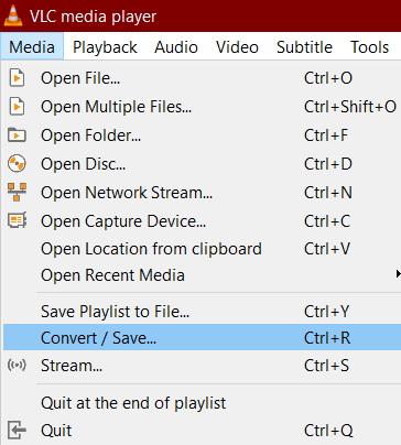
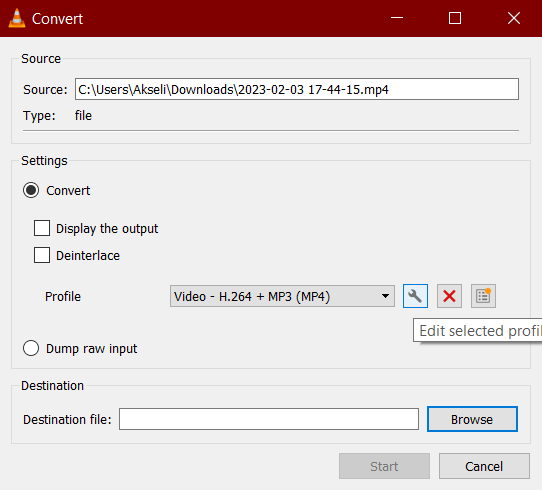
Choose file and "Convert"
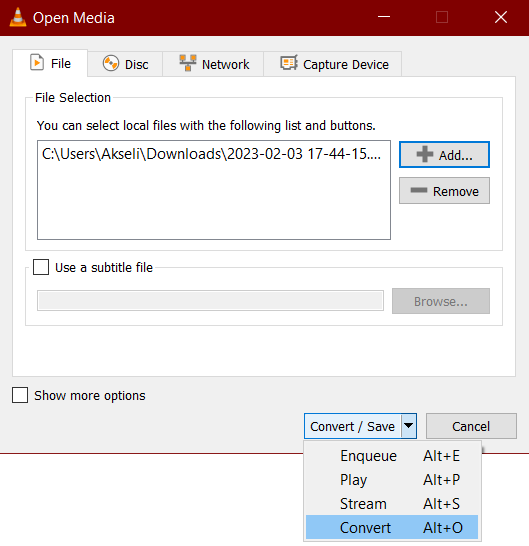
From that highlighted icon you can change the options to use. You also have to specify destination file.
Here probably the most useful option is the bitrate. Depending on your video you might also want to downscale the resolution of the video.
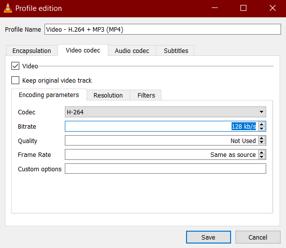
I might have gone a little heavy on the compression as the video ended up being less than 500KB. But that is good, right?
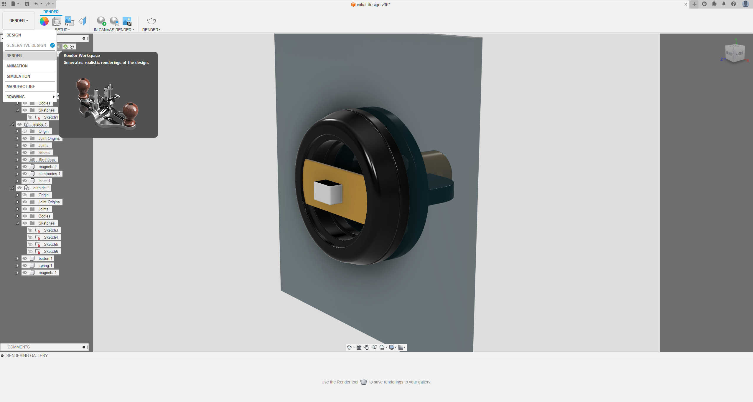
Rendering
To make a nice final visual of the model I used the render workspace in Fusion.
These are the settings, I only changed the highlighted ones.
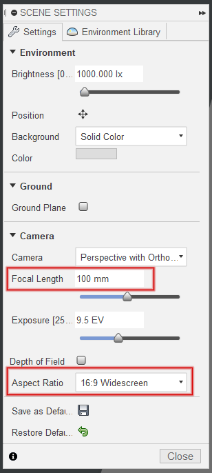
Then its just matter of positioning the camera view.
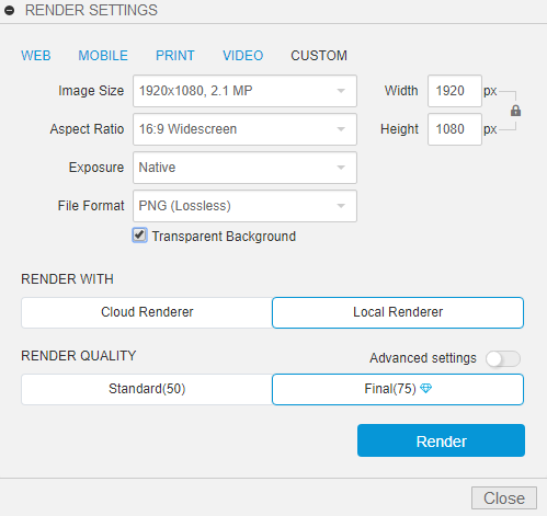
Clicking render brings up the render settings. I recommend selecting custom as it allows the most control. For some reason only local rendering allows transparent background. I use png and depending on the outcome edit/convert/compress it with GIMP.
You can see the progress in the bottom. If you use cloud rendering you can even close Fusion and come back later. Fusion 360 uses only CPU for the rendering and if yours is powerful enough it can be faster than waiting in the cloud queue.
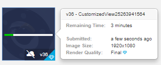
After that is finished you can download the image and use it (remember to compress!).
Result
So this is what I ended up with:
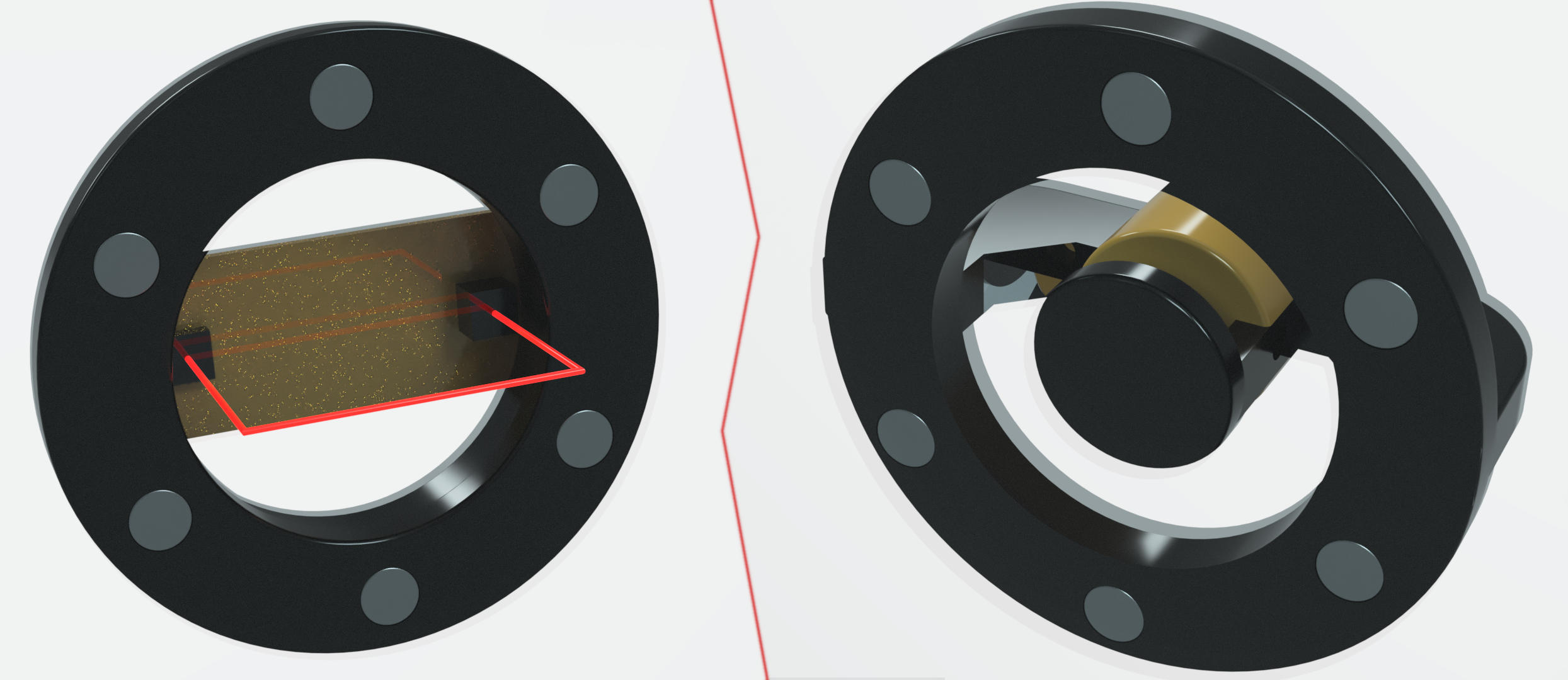
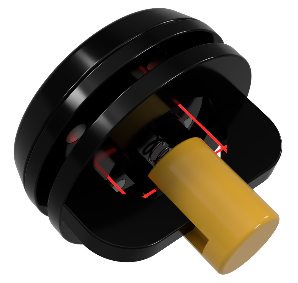
Here I experimented towards a kind of barebones style, exposing the workings of the device. It could work as a novelty item in a Fab Lab but currently it looks more like an explosive device rather than a doorbell...
Besides, depending on which kind of laser and detector I will use, it might need occlusion from other light sources. So this was a success in terms of building the idea in my head. But the current design will need to change a lot.
Source files
-
Inkscape svg file (33 KB) (right click and save-as)
-
GIMP .xcf file (499 KB)
-
Fusion 360 file (472 KB)