Final Project
Here is the journey I took when designing my final project. The first set of chapters were written very early in the Fab Academy. Jump to the implementation for the actual development.
Licence
Copyright © Akseli Uunila 2023
This work may be reproduced, modified, distributed, performed, and displayed for any purpose, but must acknowledge "Through-glass IR doorbell". Copyright is retained and must be preserved. The work is provided as is; no warranty is provided, and users accept all liability.
The licence applies to the code and design files that I have produced (downloadable source files on this site). I will however reserve all rights to the documentation (the text on this site).
Details found here.
Initial ideation
This is the very beginning of the process of my final project.
I happen to have couple of ideas that I am considering (in this order).
- Doorbell that transmits a signal from one side of a thin wall (eg. window) to another
(Smart?) Open/Closed sign for Fab LabAcrylic bending machine
Idea 1. Doorbell
This is my primary idea. The initial idea came from Fab Lab Oulu. There you can see the whole lab from behind the glass. But during weekends the door was locked and if the staff was not looking it would be hard to get their attention.
There comes the need for this special type of doorbell as it could be mounted direcly on the glass. Of course any regular doorbell could be used but this novel idea would be interesting both to make and to see. Below you can see my initial sketch for the design.
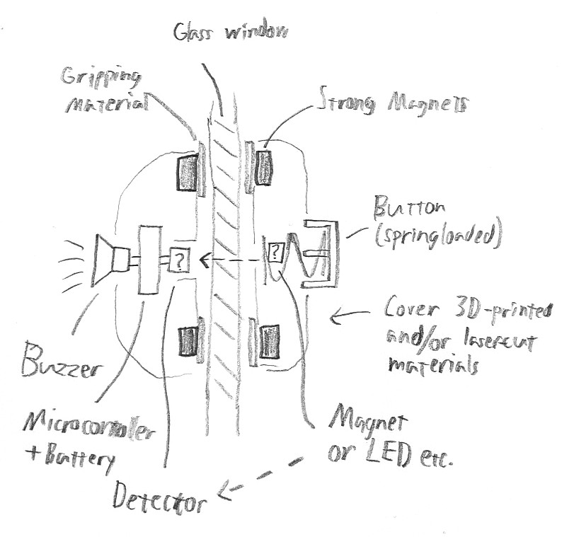
The device would consist of two units, the one on the inside and other on the outside. These units would snap together with magnets. With addition of some material that has high friction with glass it wouldn't possibly need any other type of fastening or adhesives.
The main question for this project is how to transmit the signal from pressing a button to the other side. Many options come to mind:
- Button moves a magnet physically and detect with a hall sensor
- Power a led and detect with light resistor
- Detect physical movement of the button with a optical distance sensor
- Radio signal (wouldn't make sense in this form)
- Inductive coils to transmit the signal
During the week 2 I came up with a couple of more:
- Capasitive detection somehow (?)
- Laser and two mirros with a button occluding it
- This is the idea I continued with in week 2
Still another, from Jani during a regional review (2023-02-07):
- Rely on the same phenomenon as car rain detectors
- Droplets on the glass surface scatter light
From these the preferred options would have only one power source on the inside. This kind of "passive" outside unit would work better in real life. However, one possible workaround would be to transmit power with inductive coils. If that works it would mitigate most of the downsides of the "active" outside units. So after the initial ideation I would go with one of two options:
-
Moving a magnet and detecting it with a hall sensor. This would be good as the outside unit would not need any power other than the button press. On the otherhand, the strong mounting magnets might cause too much interference.
-
Having one pair of coils to get voltage to the outside and another to get it back in. A button on the outside would close the loop. However, to my understanding, it would need alternating current and that seems difficult. Have to look more into it...
Idea 2. Open/Closed sign
Pretty basic but could potentially be really useful for example in a Fab Lab. It could be operated really simply with a switch but it would probably also need a microcontroller to qualify as a final project. The words could be engraved on acrylic with a laser and light up with an LED.
Idea 3. Acrylic bender
Not a new idea, also came up in a regional review (2023-01-30). Basically have a straight heat source with controls and support for bending the acrylic after heating. I have considered building one in the past but wouldn't be able to make the time for it. This is also why I would go with either one of the previous options.
First realisation
This is how I would attach the doorbell to the glass. The immediate issue was that the magnes that my Fab Lab have in stock are too small, even multiple ones wouldn't hold more than barely their own weight. This made me question the viability of this system...
Luckily, I did find just two slightly bigger magnets which show more promising:
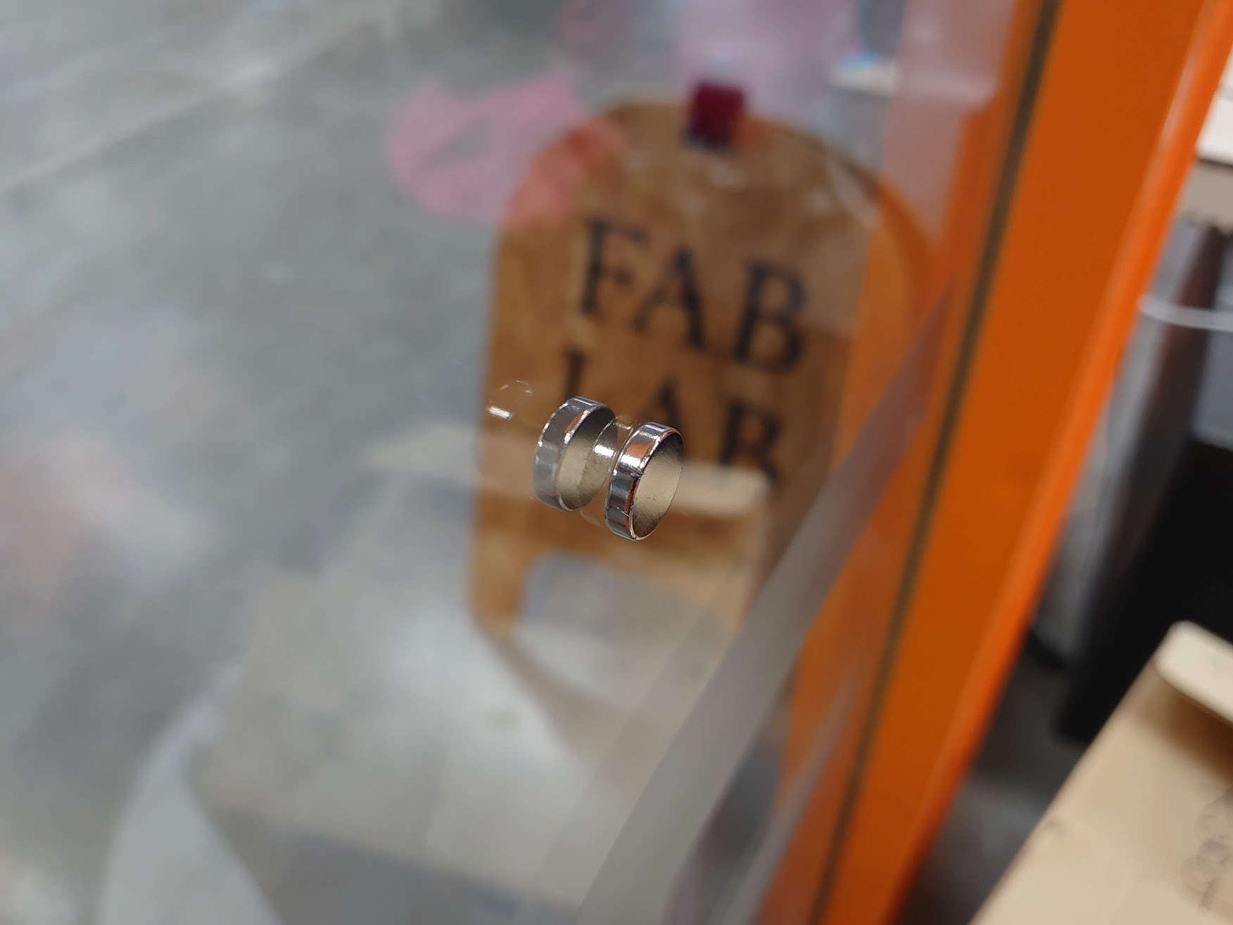
So I will need atleast similar sized magnets.
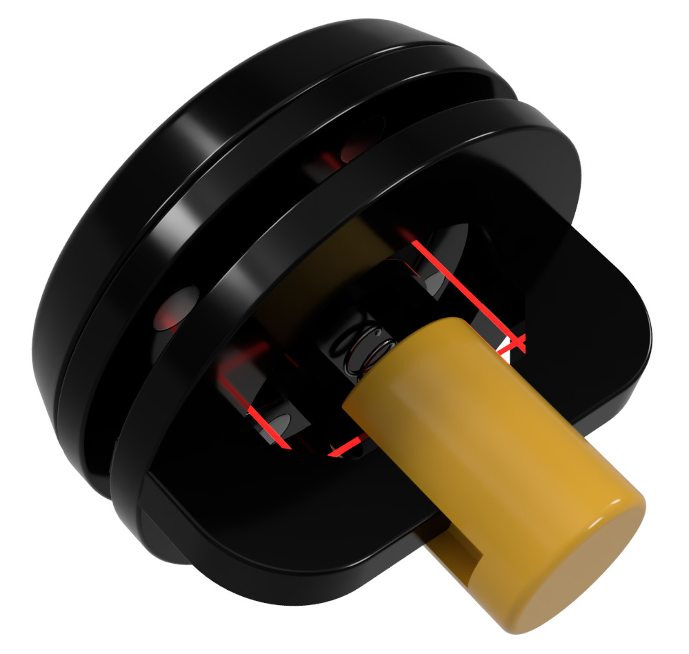
First iteration for 3D model
This render I made during week 2. It gives some insight to what the end product could look like but I'm sure it will actually look way different.
Notes from week 3 and 4
The work from these weeks wasn't really related to the final project. However, one thing I am still pondering on where to use substractive manufacturing in my project.
Manufacturing methods
Couple of options here:
- 3D print the chassis and lasercut the rings that the magnets sit in
- Laser cut most of it and only use 3D printing where necessary
- 3D print the insides and design and mill a nice wooden shell
Microcontroller
This project doesn't set any strict requirements for the microcontroller so I can use for example the any of the three Seeed XIAO boards presented in week 4.
It's possible that I'll try and use MicroPython but C would be just as appropriate.
The magnets
As mentioned in this section I need slightly bigger magnets that we currently have in stock at our Fab Lab.
I do believe the neodymium magnets can have some strenght differences even in the same size but for my need I just need the bigger ones.
Luckily there is a local shop here in Oulu that sells all kind of electronics parts and other diy stuff, including neodymium magnets. I also checked other stores and the most common size is ⌀ 10 mm X 3 mm. And the next biggest one would be 18 mm in diameter. That would be too cumbersome to include in the design so I think the ⌀ 10 mm X 3 mm will be sufficient. I can always use more magnets. For start I would expect 6 per side to be enough.
Preliminary Bill Of Materials
This is the preliminary BOM:
| Item | Purpose | Quantity | Unit Price | Link |
|---|---|---|---|---|
| Magnet ⌀ 10 mm X 3 mm | attaching | 12-20 | 1.1€ | spelektroniikka.fi |
| Mirror* | reflect laser | 2 | ||
| Spring | for button | 1 | ||
| Seeed Xiao | brains | 1 | 5€ | |
| Laser | emittor | 1 | ||
| Light sensor | detector | 1 | ||
| Buzzer | sound | 1 | ||
| Circuit board | electronics | 1 | ||
| Battery holder | power | 1 | ||
| Total price | ~20€ |
*possibly acrylic with a mirror film could be used.
Timeout
At this point I paused the final project development for couple of months to allow time for my other studies and for the completion of the weekly assignments. In the meantime I did also come up with other final project ideas but ultimately I reached the point where there's no time to pivot to another project.
Final implementation
From here on the documentation will be structured more by topics rather than purely by chronological order as it has been up until this point.
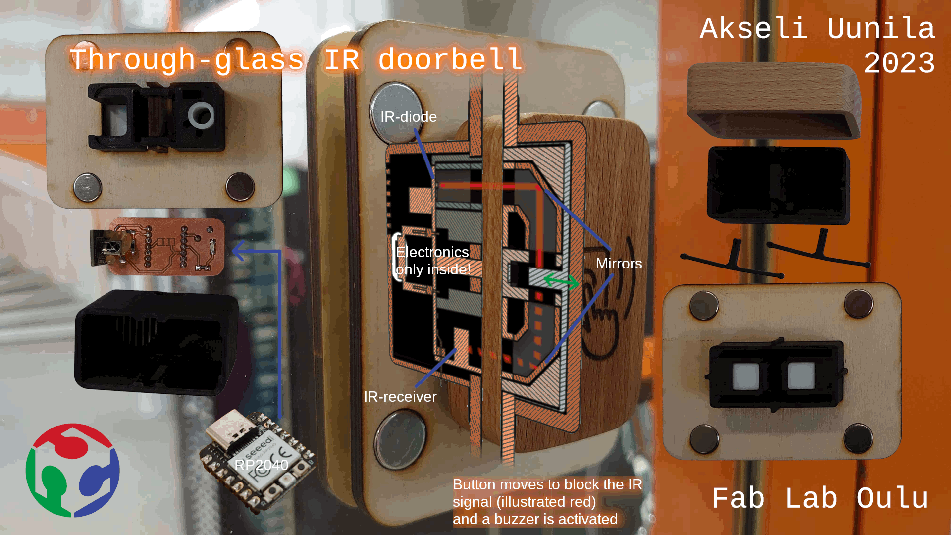
Video
Here is the presentation video of the final result.
And also the slide:
BOM
This is now the final bill of materials.
| Item | Purpose | Part ID | Quantity | Unit Price | Link |
|---|---|---|---|---|---|
| Magnet ⌀ 13 X 5 mm | attaching | - | 8 | ~1 € | Fab Lab |
| Seeed Xiao | brains | any | 1 | 5 € | Seeed Studio |
| IR diode | emittor | HIR11-21C | 1 | 0.95 € | Digikey |
| IR receiver | detector | TSOP38238 | 1 | ~1 € | Digikey |
| Buzzer | sound | CEM-1203(42) | 1 | 0.68 € | Digikey |
| Circuit board | electronics | - | 25 x 50 mm | <1 € | Fab Lab |
| Resistor 49.9 Ω | limit current on diode | 49A9 | 1 | 0.09 € | Fab Lab (digikey) |
| PLA (black) | insides | - | 68 g | 1.4 € | (generic) |
| Plywood 4 mm | Magnet frame | - | ~200 cm2 | <1 € | Mahogany.fi |
| Plywood 0.4 mm | Magnet frame | - | ~200 cm2 | <1 € | Mahogany.fi |
| Wood | button cover | - | ~100 cm3 | €€€ | self-provided |
| Mirror-like material | reflect the IR signal | - | 2 cm2 | <1 € | example |
| Total price | ~15 € |
Some details of the sourcing were discussed in week 16.
Design
The two-part design has all the electronics on the inside and on the outside only the light-blocking button. This necessitates a channel for the IR light to pass through and to be directed back on the inside sensor.
Below in the todo list are separated the design parts which need to be integrated into the corresponding units. Only thing that needs to be matched with the separate parts are the positions of the IR emitter and receiver and their channels and the positions and orientation of the magnets.
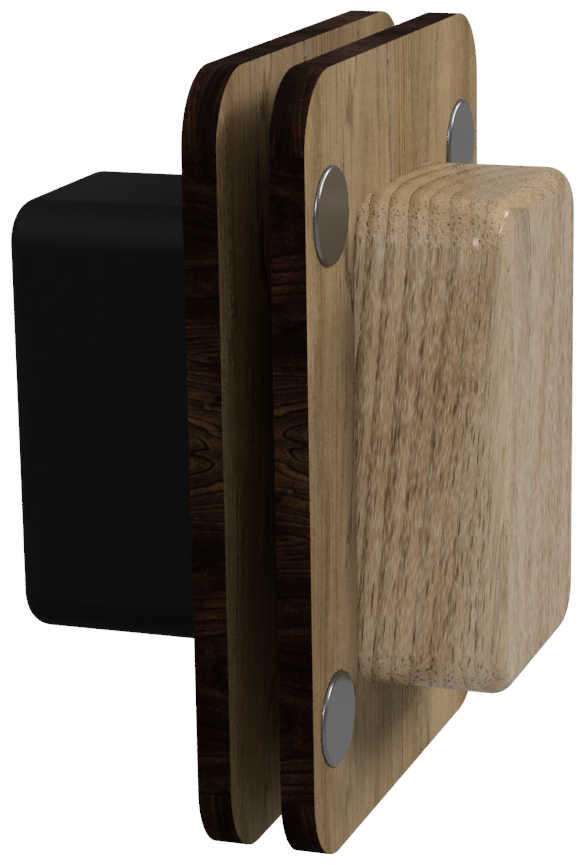
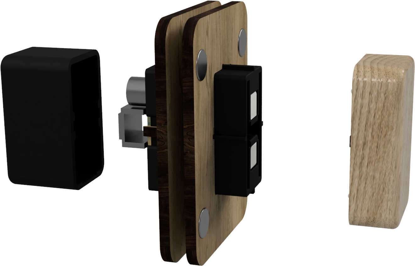
This is the final project design rendered:
Button
The button is rather big, smashable block that was supposed to have a tactile click but it wasn't recognizable. However I am happy with the wooden cover which looks nice. It has a plate with a hole in it that blocks/lets light through when pressing the button.
See this section for the making of the button cover.
Springs
The springs hold the button to the static body and snap in and out of each part. That's why I didn't use normal metallic springs. The springs are made from PLA as all other plastic parts. That works fine for the project, but for longevity those could be some other material.
Infra-red pass-through
So as earlier discussed infra-red (IR) was selected as the carrier of the signal.
My initial plan was to just have a hollow "light channel" made out of white PLA and make the other parts from black PLA. However, as the intensity of the IR is very low the white PLA alone wasn't enough to relfect the signal. Good thing is that I planned for this and the walls of the channel were both in a 45 degree angles, so I could add a mirror-like film on those faces.
The material I used was some plastic-mirror film that I believe is used with the vinyl cutter. Here any such material should work, even foil could be reflective enough but I did not test that. The BOM has the example which is quite similar to what I used. Those are usually soft enough to be cut with scissors.
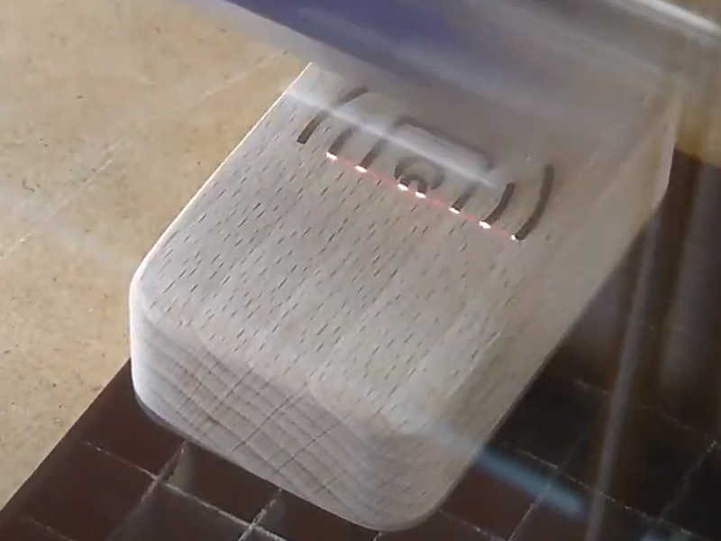
Here is a section analysis showing the principle.
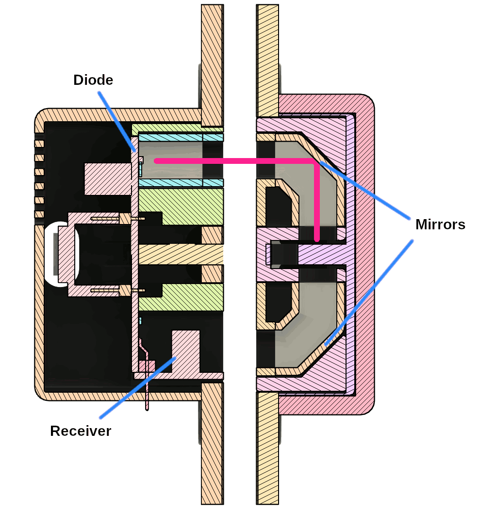
In the image the button is pressed down and IR signal cannot get through.
Magnet mounting
The two parts (inside and outside) attach together via the magnets (four on each side). You can see these magnets too in the above image. For the glass wall in our Fab Lab, which is about 5 mm, the mounting was rigid enough to let the adjacent door slam shut and the device stayed in place. However it was still a little too easy to move and then the other side could fall. I have a thin veneer between the magnets and the glass. That had suprisingly good friction, but to increase it even further some kind of soft tape (rubber, silicone) could be added.
2D design
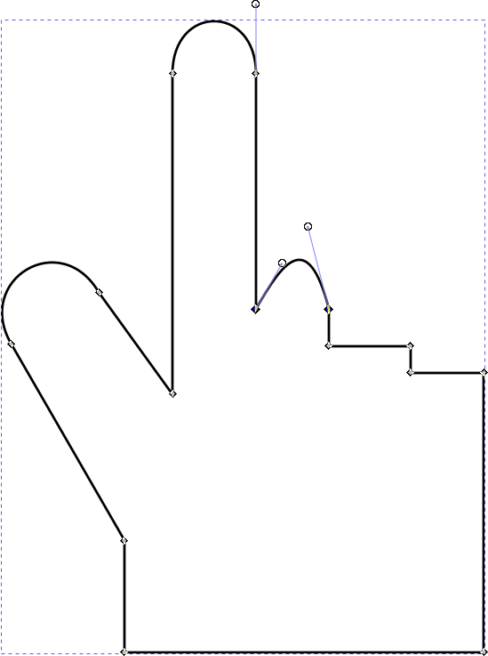
I drew this icon in inkscape to engrave on the wooden button.
![]()
,-Magnet%20frames%20thin)
I took some insipiration from searching "doorbell icon" but I drew the design completely myself.
See this section for the engraving.
Electronics
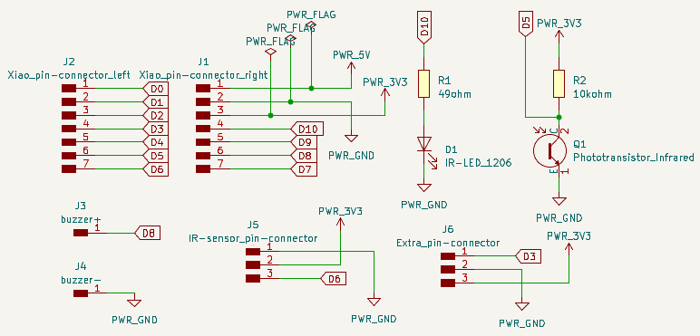
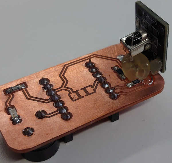
PCB
Here are the final schematics for the board I made:
And the PCB layout:
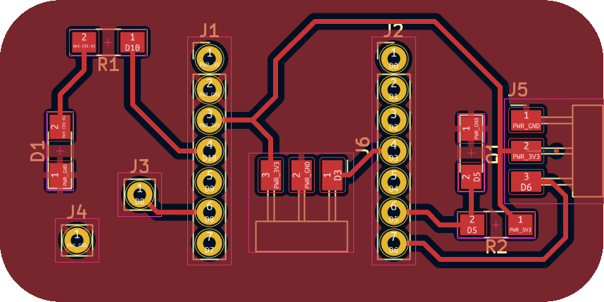
This board design evolved across the prototyping phase. I documented the designing on week 6 (first iteration) and the manufacturing on week 8 (second iteration).
This final version was basically the third iteration. The changes are rather trivial, I resized the board from 50.8 x 25.4 mm to 50 x 25 mm Added/removed/moved the same components or pin connectors.
Here I was milling the final version of the boardand soldering the components to it.
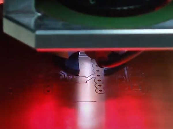
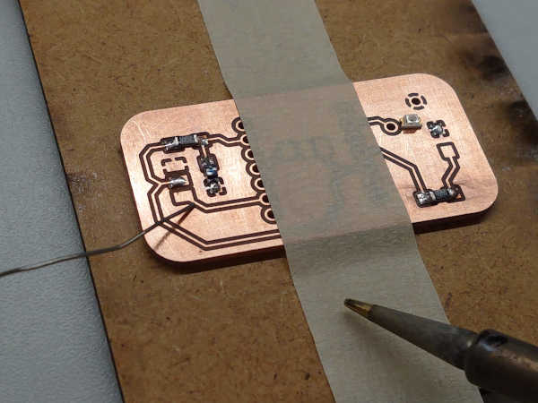
You can see the milling in action on the video.
A little problem
At the very final strech I had everything ready but I broke the PCB. The pads came off which were holding the IR receiver module.
Any sensible person would probably go ahead and make an new board. I didn't have the time / didn't want to make a new board at that point...
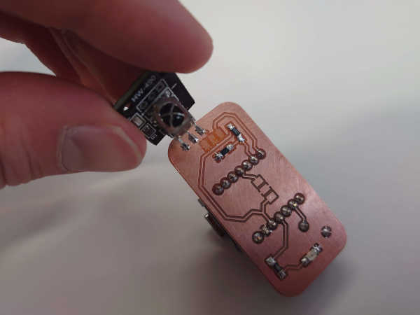
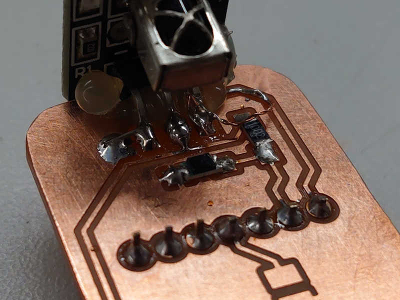
That's why you see a little hot glue on the final result.
Note that that's only fixing something that was working, not changing the design.
Buzzer
I used a magnetic buzzer and the Arduino tone() function to play a tune when the button is pressed. A piezo buzzer could also be used but I have understood that those play tunes less nicely.
IR
For the infrared signal I am using IRremote library to send and receive a 32-bit signal. This makes the system robust even if there was other IR signals present. However, there should not be much light pollution from outside as the enclosure prevents that.
Physically, I have a regular IR diode and an IR receiver as defined in the bill of materials. The diode is powered directly from the I/O pin without any amplification from a transistor, for example. This makes the signal rather weak, but also uses very little energy so it is desired.
Even though I used the separate IR receiver I left the IR phototransistor just in case if the receiver would not work.
More details mainly from week 11.
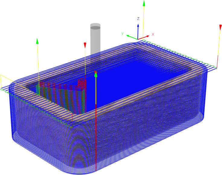
Milling
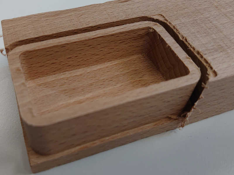
To add a little style I made a cover for the button from Beech wood. I used a desktop milling machine for this. See week 12 for the details of the process. This was exactly the same process, only difference is that I reduced the speed to 30%.
First I made the toolpaths.
Then milled the wooden piece from the underside.
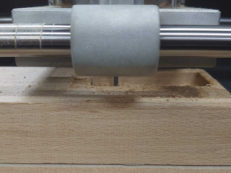
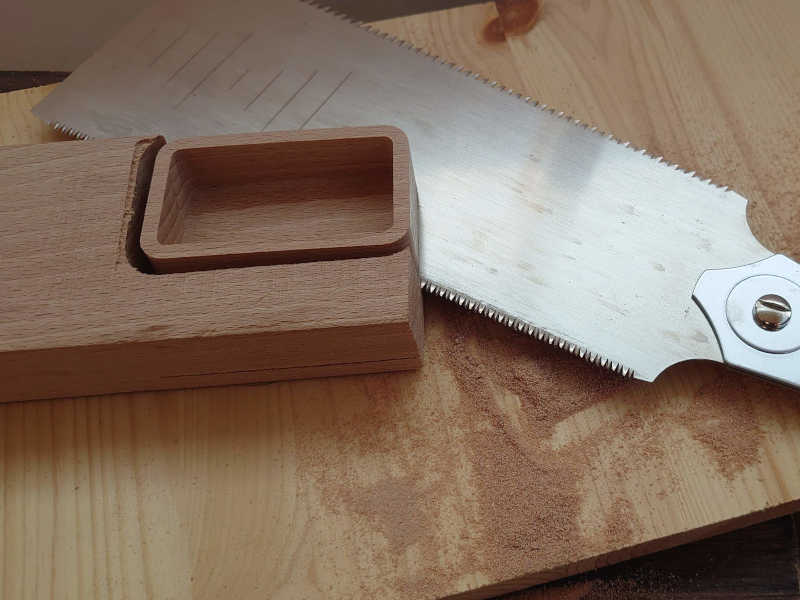
To separate the part I used a hand saw (japanese, fine teeth).
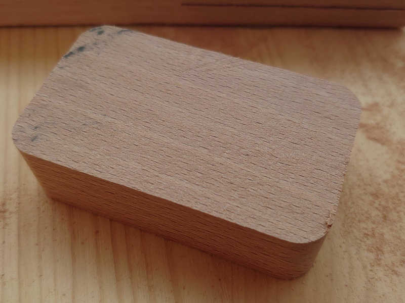
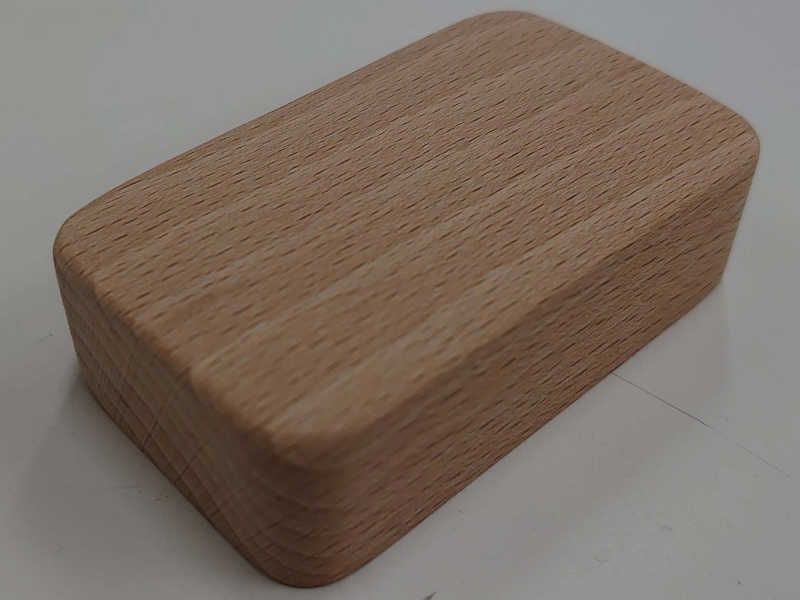
Finally I sanded the piece to round the corners and smoothen the surface.
Engraving
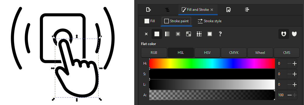
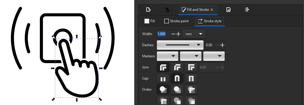
To finish the button cover I engraved a symbol that I designed on it.
To engrave I made sure the width was thick (1 mm) and the color is full black.
To export as pdf, I use "Save a copy as" (Ctrl + Shift + Alt + S) and select pdf there.
To center the engraving I had set the page size to match the wooden piece. Then I could align it with a separate scrap mdf piece.
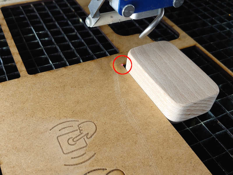
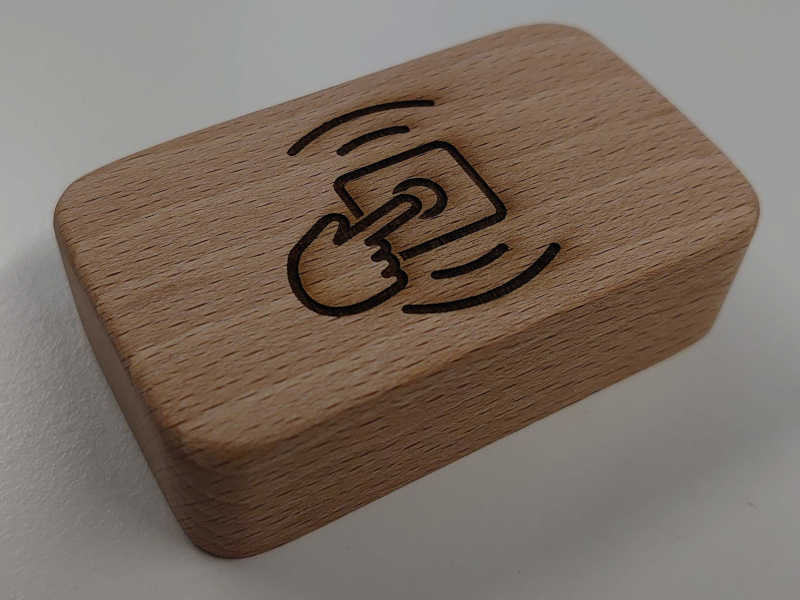
In the final video and slide you can see the button is a little darker. This is because I applied some boiled linseed oil (BLO) as a finish.
Programming
Here is the complete source code:
"Future work"
Althought this project was rather simple and it's purpose more educational than anythin else, there are still lots of directions this could be taken and also places for improvements.
The project could be developed further in any of these ways:
-
It could have IoT functionality.
This would expand the usecases so much as it makes sense to store the electronics inside, especially when the device can access your network, while still allowing input from outside.
-
Could be battery powered
The microcontroller code would need lots of optimizations for energy efficiency for this to be viable. Still that would make the most sense for this kind of product.
-
The button could be different
It could be just touch based or something else like that but here I mean that the design could have shorter travel and clickiness to make the button more tactile. This could be done by better mirrors and smaller tolerances or by havin some sort of mechanical advantage. With a small movement of the button there should be a light blocker that moves enough to completely block the signal.
Some minor improvements to the current design include:
-
Buzzer could have a transistor to amplify its sound.
-
Button could be supported better so that it doesn't pivot and seize.
-
Code could always be optimized.
-
After the mirrors were added there is not a significant benefit from the white PLA light channels. Those could be part of the main bodies and printed as one.
-
There could be some LED or other feedback that the button press has indeed been registered.
Time spent
I kept track of the time used for Fab Academy on a spreadsheet and the total was about 390 hours. Weekly average comes down to around 20 hours.
Generally it should be pretty accurate as almost all work done was recorded on that sheet. However, with any even slightly creative work, it occupies the mind even when you are "not working".
This graphs shows that there were more intense times too.
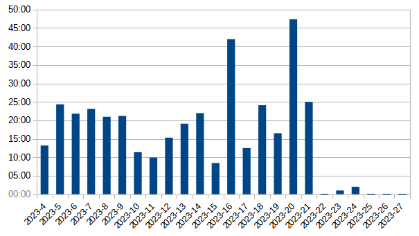
At the end I had something else to do so I had to finish early. However there are also Fab Academy related stuff I was not so strict to record on the last couple of weeks.
The units are hours:minutes and the dates represent calendar weeks. However, the week is split by Wednesdays as thats when the Fab Academy assignments begun.
Source files
-
Code files
-
pitches.h (from Arduino examples)
-
3D files (.step)
-
Inside parts
-
Outside parts
-
-
2D files (.svg)
-
Magnet frames thick parts (4.4 mm)
- Includes a clip that holds the PCB
-
- For engraving
End of documentation.