11. Input devices
This weeks work is intertwined with electronics production week and input devices week. On electronics production week I made the circuit board which has both infrared output and input. So this week I will be trying out reading the input from the IR receiver.
Group work
For this weeks group work we probed both digital and analog sensors with an oscilloscope to see the output.
I was mostly interested in an IR phototransistor which I could use in my final project. However, we were not able to reliably measure the IR phototransistor (The images on the group page is of the visible light photoresistor). The signal from the IR phototransistor was very noisy and there were no evident changes when we used an IR remote controller as the source of IR signals. This could just be that the voltage changes were so small. And/or it could be that the circuit wiring is somehow incorrect.
I think for future IR endeavours I will use an actual IR sensor as all the tutorials I came across use those as well.
Testing the buttons
I used the following script to test the buttons. The NeoPixel related stuff is explained in embedded programming week.
#define NEOPOWERPIN 11 // Provides voltage for the built-in NeoPixel
#define NEOPIXELPIN 12 // Datapin for the the built-in NeoPixel

#define BUTTON1PIN D2
#define BUTTON2PIN D3

Adafruit_NeoPixel pixels(NUMPIXELS, NEOPIXELPIN, NEO_RGB + NEO_KHZ800);

void setup() {
    pinMode(NEOPOWERPIN, OUTPUT); // initialize digital pin NEOPOWERPIN as an output.
    digitalWrite(NEOPOWERPIN, HIGH); // Power for the NeoPixel

    pinMode(BUTTON1PIN, INPUT_PULLUP);
    pinMode(BUTTON2PIN, INPUT_PULLUP);

    pixels.begin();
}

void loop() {
    int red = 0;
    int green = 0;
    int blue = 0;

    if (!digitalRead(BUTTON1PIN)) {
        // Button 1 is pressed
        green = 100;
    } else {
        green = 0;
    }

    if (!digitalRead(BUTTON2PIN)) {
        // Button 2 is pressed
        red = 100;
    } else {
        red = 0;
    }

    pixels.clear();
    pixels.setPixelColor(0, pixels.Color(red, green, blue));
    pixels.show();
}
! in the if statements.
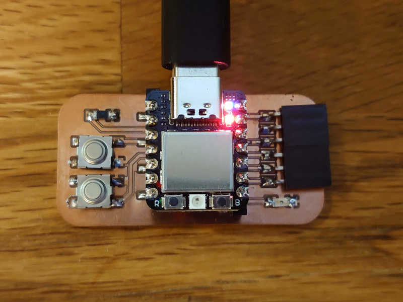
This is what it looks like without any buttons pressed.
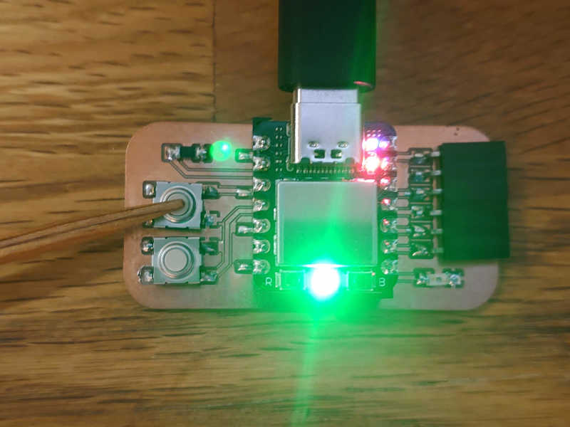
First button pressed, green light.
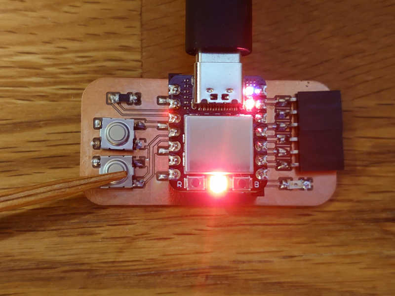
Second button pressed, red light.
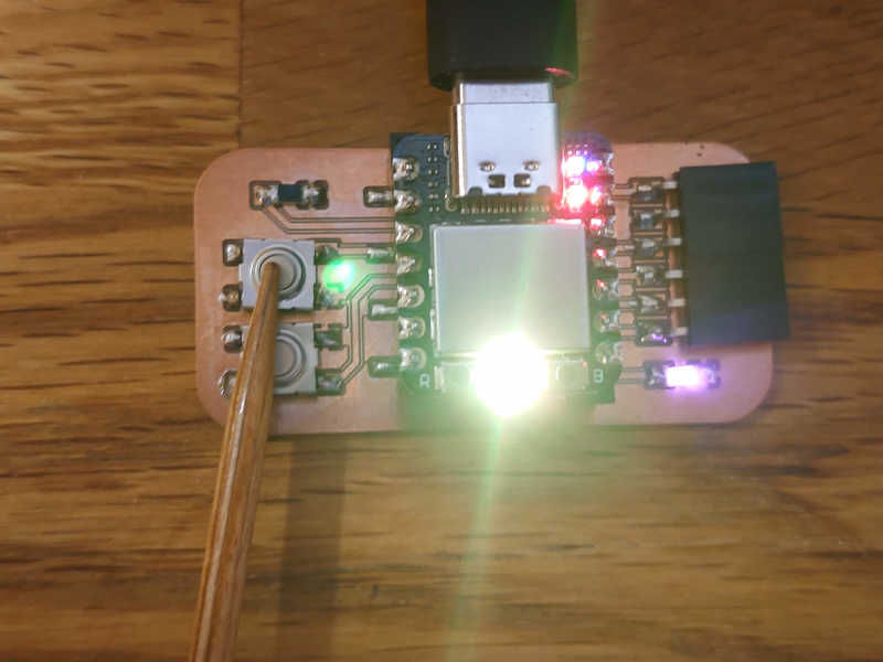
Both buttons pressed, yellow light (seems white in camera).
So this way the buttons can be used to control things, like the NeoPixel.
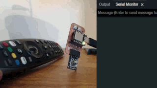
IR receiver
I decided to ignore the IR phototransistor for now and go straight into using the separate IR receiver (HW-490) which comes in many common and cheap "arduino sensor kits".
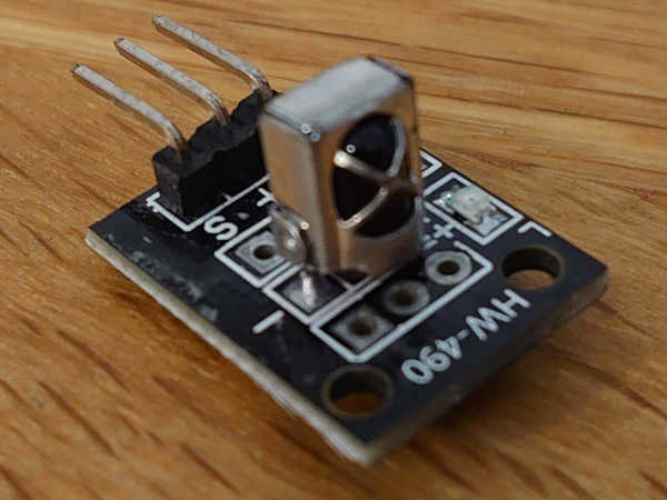
It has three pins: a voltage (+), ground (-) and data (S).
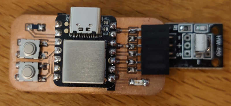
To much of my surprise, the sensor can be just plugged in directly to my board! (Which has the Seeed XIAO SAMD21 this time)
Which is so convenient.
To read the sensor I used this IRremote library which had also a simple example on the page. I only changed the pin identifier:
#include <IRremote.h>

#define RECEIVER_PIN D10

IRrecv irrecv(RECEIVER_PIN);

decode_results results;

void setup()
{
  Serial.begin(9600);
  irrecv.enableIRIn(); // Start the receiver
}
void loop() {
  if (irrecv.decode(&results)) {
    Serial.println(results.value, HEX);
    irrecv.resume(); // Receive the next value
  }
}
Now, that example code prints the HEX values of the signals transmitted from an IR device.
There are some standards in the protocols that for example TVs use. I have an LG TV which has this "magic remote". I was not sure what is the defaul protocol in the receiver, but I tested it directly.
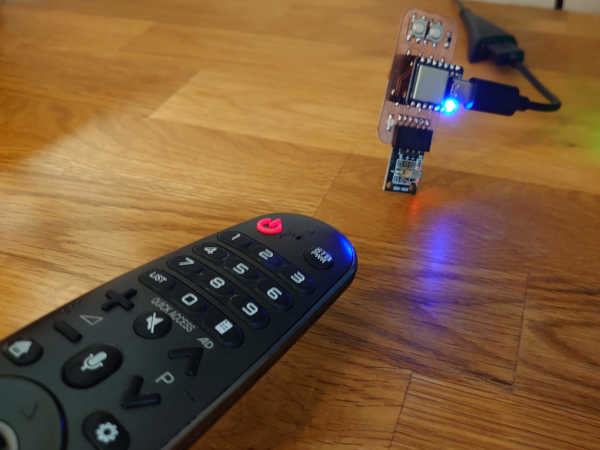
Sadly, all of the buttons in my remote produced FFFFFFFF.
However, surprisingly when I opened my phone near the receiver,
it printed A0F22FDA constatly when the screen was open.
I figured this is from the proximity sensor in the phone
as it shouldn't have anything else related to IR.
Also if the signal was disturbed it would display something else.
This could be used to detect my phone screen opening,
not sure how useful that is though.
Reading the signals
This newer, more sophisticated example provides much more information.
#include <IRremote.hpp>

#define RECEIVER_PIN D10

void setup()
{
  Serial.begin(9600);
  IrReceiver.begin(RECEIVER_PIN, ENABLE_LED_FEEDBACK); // Start the receiver
}

void loop() {
  if (IrReceiver.decode()) {
      // Serial.println(IrReceiver.decodedIRData.decodedRawData, HEX); // Print "old" raw data
      // USE NEW 3.x FUNCTIONS
      IrReceiver.printIRResultShort(&Serial); // Print complete received data in one line
      IrReceiver.printIRSendUsage(&Serial);   // Print the statement required to send this data
      IrReceiver.resume(); // Enable receiving of the next value
  }
}
Now when I press the buttons on my remote it tells the protocol is NEC and separates the address and command, among other things. For example when pressing the powerbutton it prints this:
Protocol=NEC Address=0x4 Command=0x8 Raw-Data=0x0F708FB04 32 bits LSB first
Send with: IrSender.sendNEC(0x4, 0x8, <numberOfRepeats>);
Protocol=NEC Address=0x4 Command=0x8 Repeat gap=40000us
And when opening my phone screen:
Recording the necessary signals
These colored buttons are rarely used for anything anymore so those could be useful for custom applications.
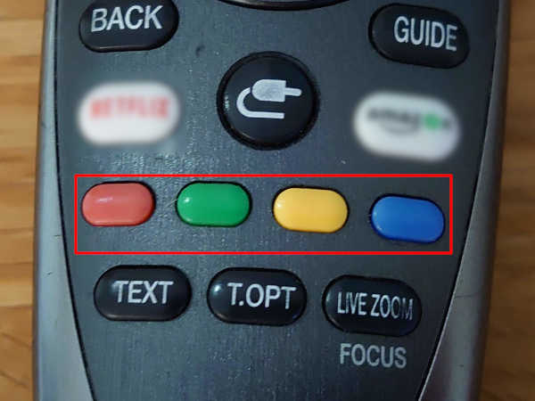
Pressing the button and using the previous example allowed me to gather this information.
| Button | Raw-data | Command |
|---|---|---|
| Red | 0x08D72FB04 | 0x72 |
| Green | 0x08E71FB04 | 0x71 |
| Yellow | 0x09C63FB04 | 0x63 |
| Blue | 0x09E61FB04 | 0x61 |
Also, all have the address of 0x4.
Result
With the help of the documentation
I knew that I can access the data from IrReceiver.decodedIRData
and that allows me to do this:
And here is the result:
By the way, I also watched this video for reference but most of the code was written by referring to the github page of the library.
Well, this is nice library which makes it trivial to read (and likely send) IR signals both for controlling existing devices and for custom projects. I would expect that for the final project I would need to either go lower level or implement some more complex functionality.
Anyway, that's it for this assignment. I will be taking advantage of this in week 9 which is the output week.
End of week 11.