7. Computer-controlled machining
This week our task was to "make something big". I designed and manufactured a material organizer for laser scrap pieces.
Group work
We went through the safety training in the group work and we manufactured a clothes hanger that we then measured.
The measurements can be found from the group page. There were some variations in the measurements and the designed dimensions. However, I would contribute that to inaccuracies in the measurements rather than the machine. Of course, there are some variations in the range of less than 0.1 mm but measuring those with any wood based material is quite challenging.
Even though I have used the CNC machine in question many times I took the safety training seriously. I don't want to be the example of an overconfident "I know what I'm doing" person. And so I operated the machine with caution as I normally would.
Setting up
To create too paths for a cnc machine you need the post processor for that machine. You also need the tool library but you can also create this yourself if you know what tools you have available.
Our instructors provided these:
Which you need to download and then import in the Fusion 360 manufacturing workspace:
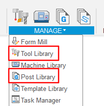
Both menus have import button and it as simple as selecting the correct file. I went to further detail in this video from week 3.
Modeling
I will use fusion 360 for this.
Below is a scrap material "organizer" I have made previously for our Fab Lab. It's a little.. overutilized.
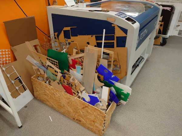
I will make a new design, which will be simpler and larger but still fit in the one large OSB sheet that we were provided.
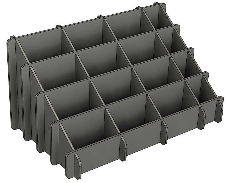
The design is rather simple in terms of 3D modeling. 3D modeling is covered more in-depth on week 2. The joints are probably the simplest there can be. However, there are some new aspects that are specific for CNC milling.
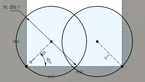
Dogbones
Because the tools are round and the diameter is rather significant (compared to laser) inside corners will not be sharp. This would cause fit issues if not handled properly.
That can be mitigated with dogbones which mean the tool cuts "in" the corner so that it will "touch" the inside corner. It results in removing slightly more material thats needed but usually that's only a slight esthetic drawback.
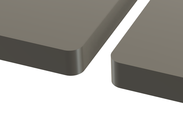
I made dogbones in the model by cutting extruded circles from the corners:
This is what it looks like in the model:
As the slots are quite narrow for a 8mm tool the dogbones will combine. I offset the faces to account for this. I used interference analysis to see how much the parts overlap:
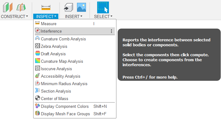
After selecting the bodies and pressing compute it shows where the volumes overlap.
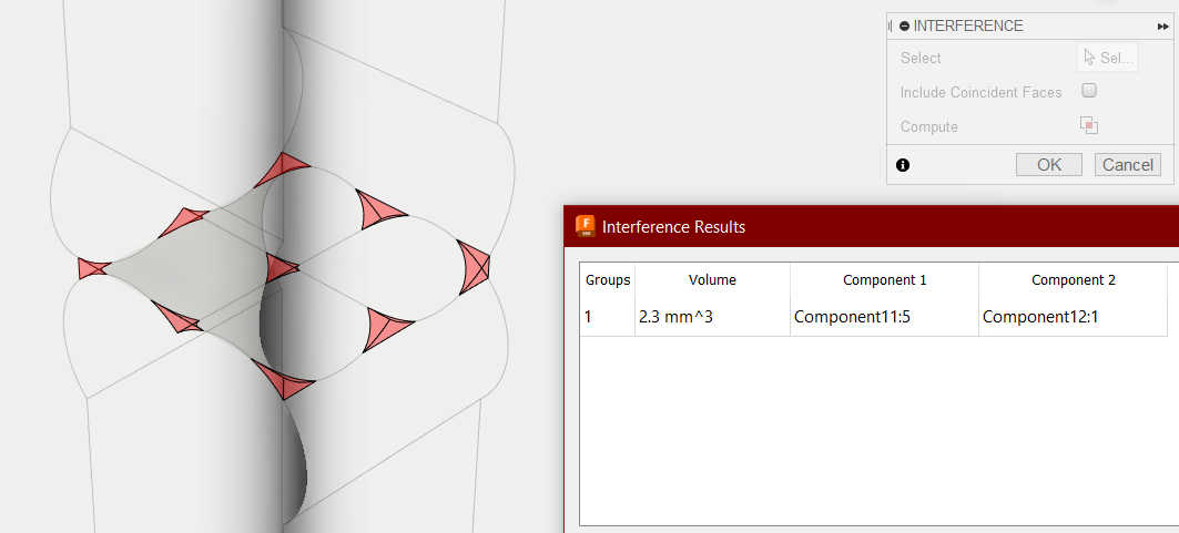
This slight overlap is good as the material will compress easily for that minimal amount.
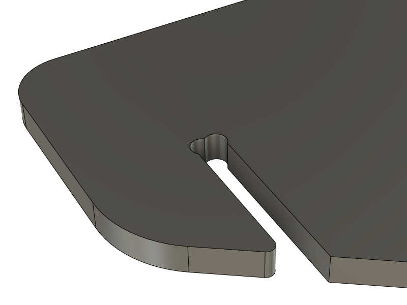
I also added fillets to all of the slot openings to make assembly much easier:
Now the model is ready for the next step. The source file for this is at the bottom of this page.
Creating toolpaths
This is the step where the file that controls the actual CNC operation is created.
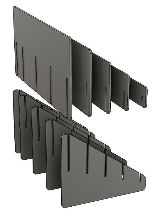
Arrange parts flat
First we need to place the parts in a flat plane to match the flat OSB sheet that will be used as material.
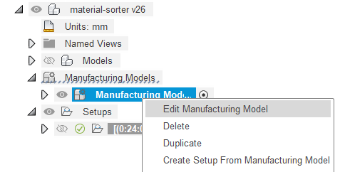
TIP: Instead of doing this in the model it's much better to create a manufacturing model:
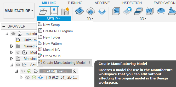
This allows making separated modifications to the model that are only needed for the manufacturing.
Now that that's sorted we can actually do the arranging.
For designs with very few parts it's suitable to just use the move tool (shortcut M)
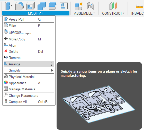
but for anything more complex there is a tool in Fusion for this, Arrange.
For this first make sure every body is it's own separate component.
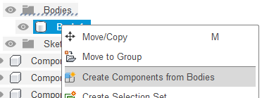
Then use the arrange tool:
Select all of the components.
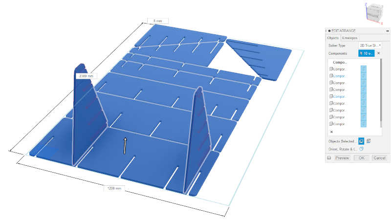
Then select the X/Y plane and set the workpiece dimensions.
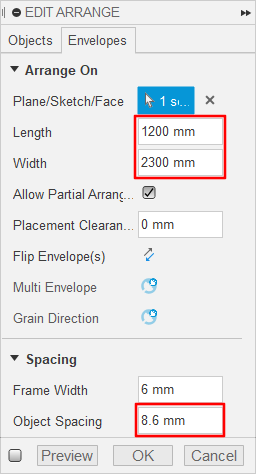
Also make sure the object spacing is more than the tool width you are going to use.
I had to move the parts manually as the automatic arrangement was not the most optimal. I was able to place almost all of the parts in the sheet:
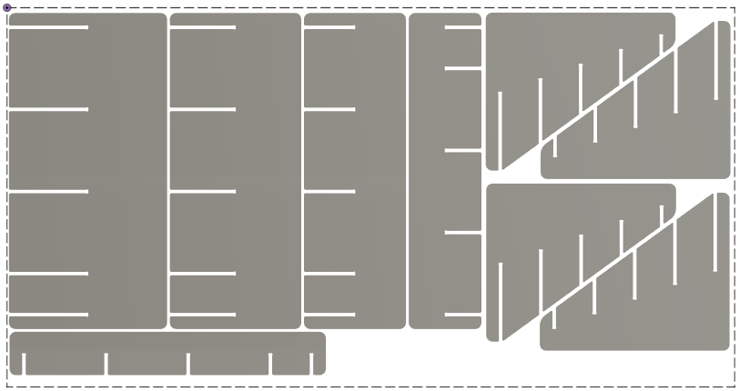
The last missing triangle divider is sold separatedly..
Now we can actually make some toolpaths for this arrangement.
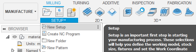
Setups
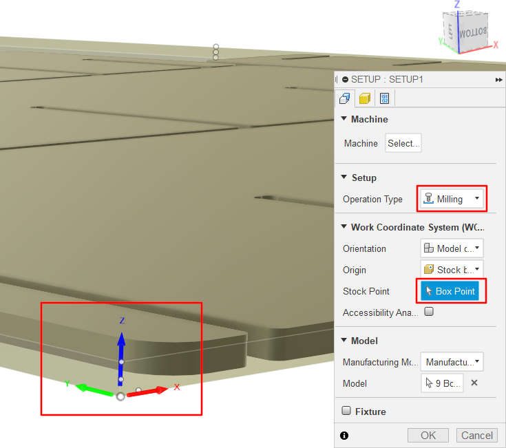
Start by creating a Setup. Setups are used to define the workpiece/stock, orientation and operation type. For this purpose one setup is enough but if you do for example double-sided CNC milling another setup can be used for the other side.
Because we are using a vacuum table I will select the bottom corner as the origin.
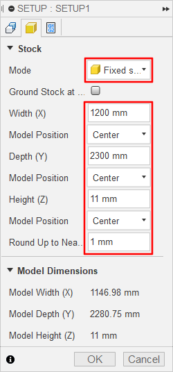
And in the stock tab I set the dimensions as the size of the OSB sheet we will be using.
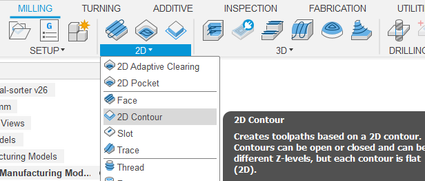
Toolpath
Different milling strategies work for different object. As this design doesn't have any pockets or 3D features, I only need this 2D Contour.
I used the 8 mm flat tool from the provided tool library.
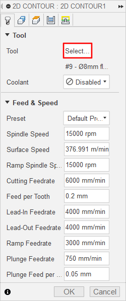
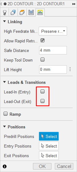
In the Linking tab just make sure leads are turned of as those are only needed with metals.
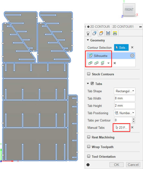
From the Geometry tab I selected Silhouette and added some manual tabs to prevent the smaller cutoffs from flying away. Those are shown as the dots in this image:
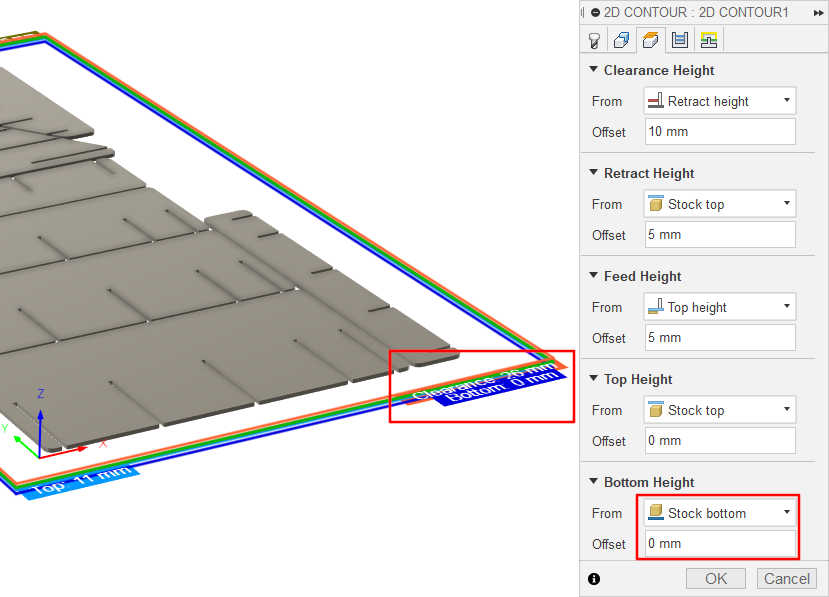
Then for the Heights I set the bottom to "stock bottom"
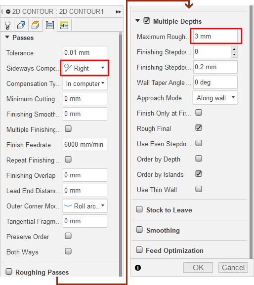
Lastly, in the Passes I set the direction to "Right" or more commonly "Conventional milling" As that gives better surface finish for woods and similar materials.
Also by default the contour would be a single pass but it should be done in steps. I used 3 mm as the maximum stepdown.
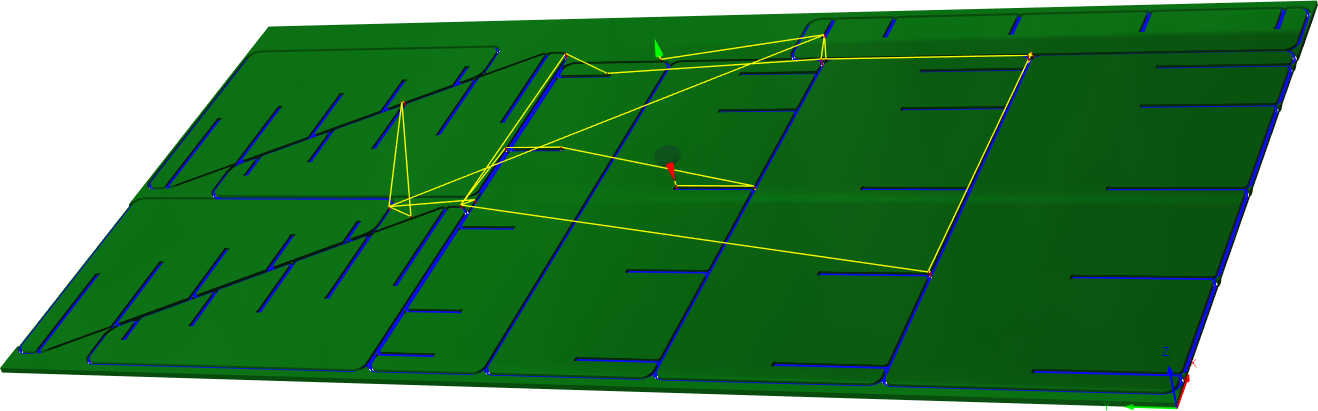
After clicking ok Fusion will generate the toolpath and then show this preview.
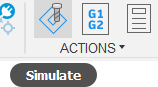
For more accurate preview and checking the simulate tool is essential.
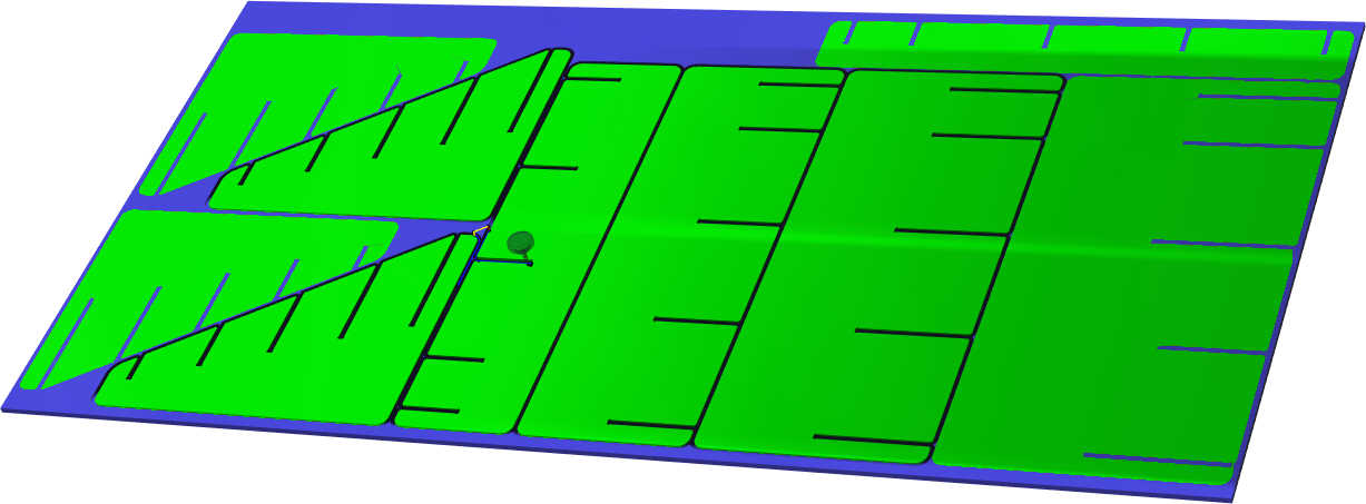
It will also warn about possible collisions but of course the responsibility is on the maker.
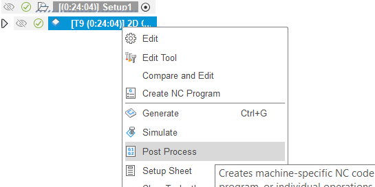
Exporting
To export the NC code you need the post processor as mentioned in this section. Then select the setup or toolpath(s) that you want to export. You should export different files for each tool to make the tool changing easy.
There will be pop-up menu but the default settings are good after selecting the correct post processor.
Source file is at the bottom of this page.
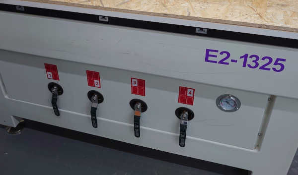
Machining
Our fablab has this Rensi E2-1325 CNC milling machine. It has a vacuum table. Apparently air flows through mdf...
The steps for the machining job are:
- Power up machine
- Main power switch on
- Power on
- Start up PC
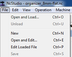
- Open NcStudio and confirm autohome
- Load nc file from usb stick
- Change the correct tool
- Position workpiece on the vacuum table
- Turn on vacuum table
- Calibrate the Z axis
- Zero the X and Y axes to position the job
- Simulate job for assurance
- Start machining
- Make sure you know how to stop it!
- Turn on dust collector
- Click
startfrom NcStudio
- Watch the operation
- Adjust feeds and speeds if needed
- Clean up after yourself
For jobs using multiple tools, repeat steps 3. and 6.
Next I will go to the details of the steps with images.
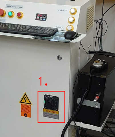
Powering up the machine
First switch on the main power:
Then power up the machine from that green button
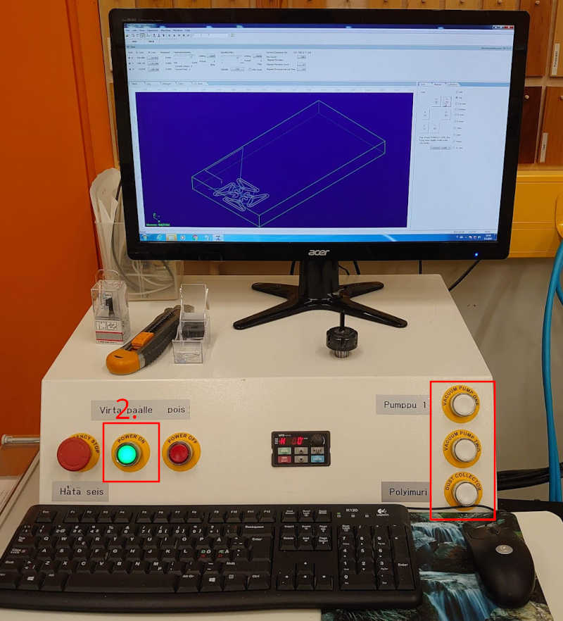
Those vacuum buttons on the right will be used later.
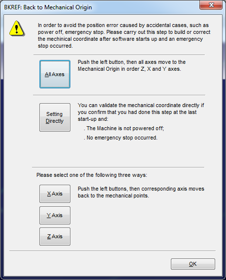
Starting up the computer
Once the machine is powered go ahead and start NcStudio. It will ask to "autohome" so click on All axes.
After that you can Open and Load your .nc file.
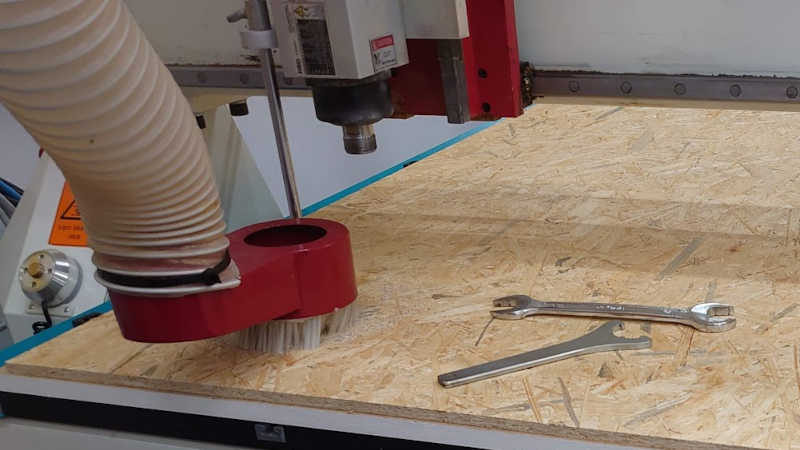
Changing a tool
First lower the dust collector cover and remove the chuck and collet from the spindle.
I will be using the 8 mm flat endmill which I used when creating the toolpaths.
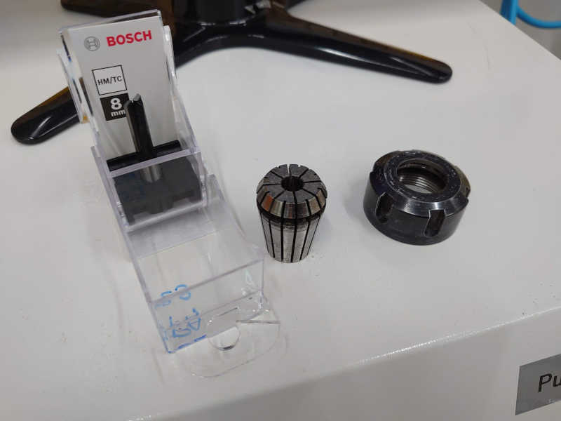
First the right sized chuck will be inserted into the collet.
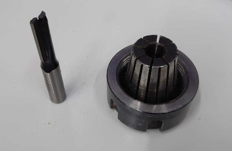
And then the tool slides in.
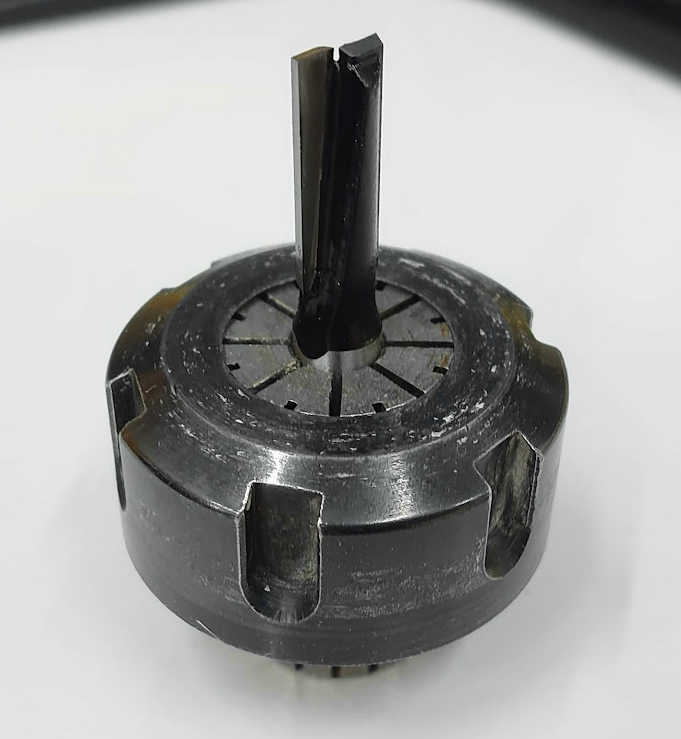
This whole pack can then be threaded to the spindle.
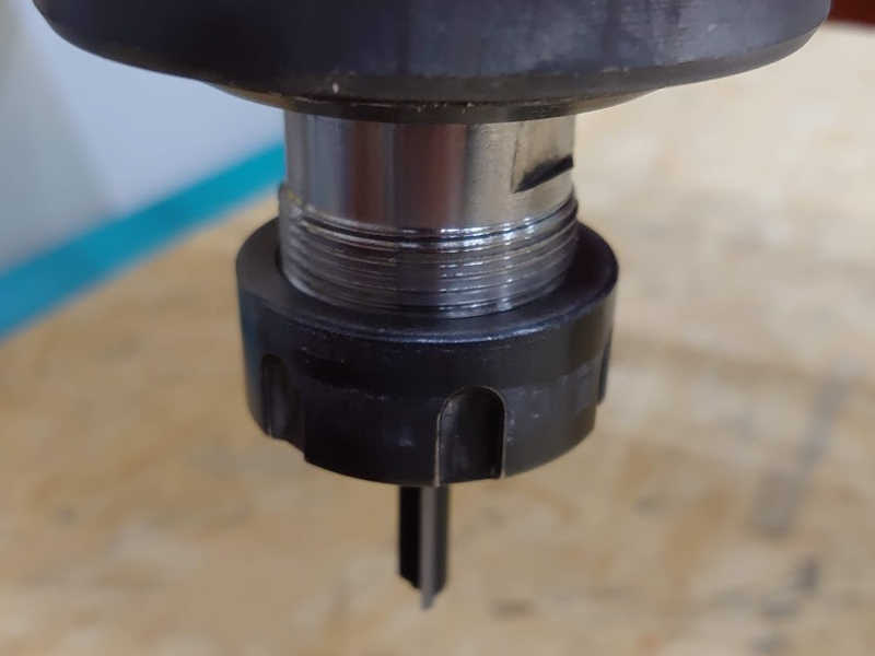
It should be tightened with the wrenches to a moderate tightness.
Calibrating the Z axis
First, start the vacuum and check the valves are open! This is important because the vacuums pulls the table down significanly.
Those valves can be used to restrict airflow to certain sections of the table if the workpiece is smaller.
We zero the Z axis (height) to the top of the vacuum table (bottom of the workpiece) So when done correctly the tool shouldn't cut into the table and it wont have to be milled flat that often.
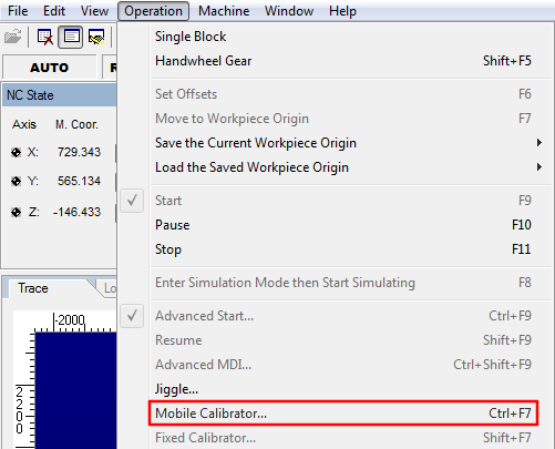
To do this the machine has this thing called "Mobile calibrator". The machine will lower the toolhead until it hits the metal top of the puck.
Make sure the table is dust-free (the dust in the image fell after the puck was placed down). Position the toolhead manually to about 5 mm over the puck:
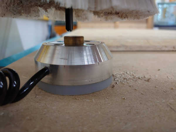
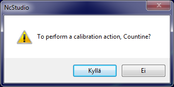
And start the calibration from the PC
When clicking "Yes" on the prompt the toolhead will start to lower. So make sure the puck is positioned correctly. It can be held by hand if the cable is trying to pull it away.
This will need to be repeated if the tool is changed.
Zeroing X and Y axes
The X and Y axes are zeroed manually from the NcStudio. This is done by eyeballing the position of the cutting tool to the edges of the workpiece. (Or where ever the origin in the file is)
This method is sufficient for us as the workpiece has more than couple millimeters of extra space.
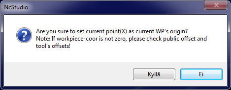
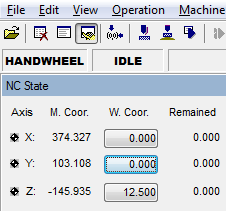
Each axis can be zeroed separatedly. Click on the corresponding "W. Coor." button.
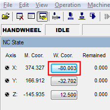
It has a confirmation prompt, click "Yes".
After zeroing both axes:
Start machining
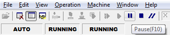
Before you start make sure you know how to stop the machine!
The best way to stop the machine is to press F10
as this allows you to continue machining.
In risk of any injury or damage to human or machine do not hesitate to hit the emergency button.
Next to it there is also the stop button F11 which you could use if you notice the operation failed for some reason.
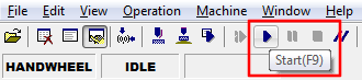
To start the machine press F9 or click the start button.
During machining
During the machining you should observe the process both visually and audiolially. If there is are excess noises you should probably lower the feed speed. If the machine is making dust rather than chips you are going too slow with the feed in relation to the spindle speed.
You can adjust the feeds and speeds (relatively, 0% to 100+%) from the sliders in the NcStudio.
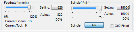
The actual (100%) values are defined earlier in Fusion360. You can see the values in the second image of this section.
Issues
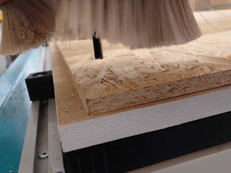
As mentioned in calibrating the Z apparently the vacuum should be on as the corner of the table rests higher without the vacuum...
This resulted in the Z being zeroed slightly too high (almost a millimeter):
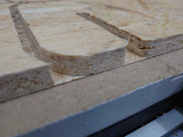
Luckily, it was not too hard to go through the slots with a hand saw.
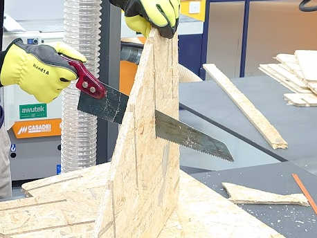
Though next time I will certainly double check the Z axis calibration..
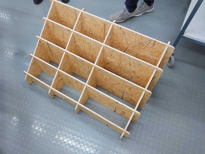
Assembly
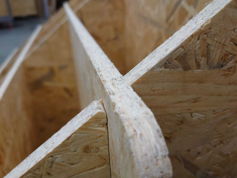
After that tedious "post processing" The parts slide on very nicely:
Some of the last pieces needed a little help of a mallet. After that the parts seated very firmly.
Result
And here is the thing assembled.
The product is very versatile as it can be used in atleast three more orientations:
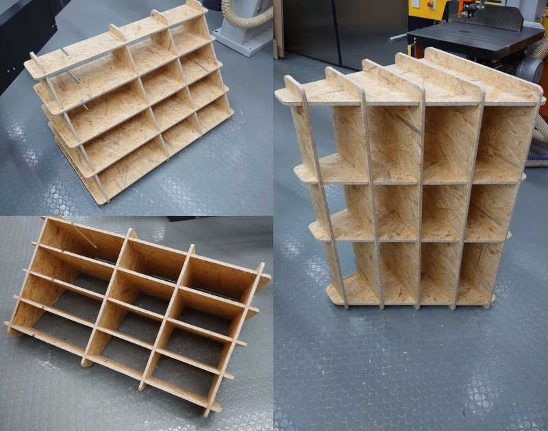
There would have been a slot for one more vertical divider but it didn't fit on the sheet so I didn't make it.
Source file
Here is the Fusion 360 source file that includes the toolpaths:
- Fusion 360 file (1221 KB)
End of week 7.