9. Output devices
This weeks work is intertwined with electronics production week and input devices week. On electronics production week I made the circuit board which has both infrared output and input.
And for the input devices assignment which I made before this one, I used an IR Receiver to read signals from a remote.
So this week I will be trying out controlling the IR LED on my board.
I went through the programming procedure in embedded programming week.
Group work
In this weeks group work we used a multimeter and an USB tester to measure power usage of NeoPixel led and the microcontroller.
The main takeaway was that RGB leds typically consume a fraction of the power when not using a full white color which makes sense. This just means that sometimes it would be ok to use for example the NeoPixels from a low-current power source like the microcontroller pins if the brightness is limited from the program.
IR LED testing
To test if the IR LED on the board actually works I wrote this simple script in Arduino IDE.
#define IROUTPUTPIN D0

void setup() {
    pinMode(IROUTPUTPIN, OUTPUT);
}

void loop() {
    digitalWrite(IROUTPUTPIN, HIGH);
    delay(1000);
    digitalWrite(IROUTPUTPIN, LOW);
    delay(1000);
}
It toggles the IR LED on and off with a 1 second delay.
And as you can see the IR LED is ligthing up.
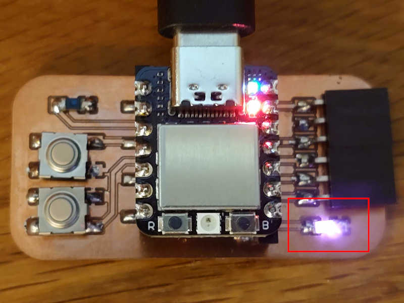
That is visible to a phone camera but not to the naked eye.
Sending IR signals
Refer to input week for that was written before this.
I will next try to emulate a TV remote with my board. As a reminder I have an LG brand TV.
The tests presented in that input weeks page gave me directly this function to use for sending:
Using the code from the input week I found that the
command for my remotes "select" or "OK" button is 0x44
For the sending I again referred to the documentation of the library.
Mainly it states that I have to define the IR output pin before including the library.
I should also mention that here
it's explained why the library is included as .hpp instead of .cpp (or just .h as is usually done).
I don't quite grasp the differences, but it's done due to lacking features for compilation options in Arduino IDE.
And also that if in doubt, three is a good amount of repeats for the signal. But I don't think that should be used for something like select as I want to do that only once (we will find out). It also possible that the TV only acts on the command once. Therefore I should probably start with this:
Result
Now I could write this code to send two different commands with the two buttons. Please note that also the buttons were tested in input week.
Testing it and.... it doesn't work?
My TV isn't turning on even though I can see the IR LED lighting up through my phone camera.
When I moved the transmitter really close to the TV (like 30,48 cm for example), and it works!
Seems that the IR signal is very weak. When I researched some more I understood that IR diodes need a lot of current (eg. 100mA at 1.45V). That means that when powering it from a regular I/O pin it's severely underpowered (Those pins can give around 40mA max). This could be fixed by using a transistor for amplifying the signal or, as the documentation suggests, putting couple of the IR LEDs in series and omitting the resistor. This would give more light energy for "free" as the energy that is currently "wasted" on the resistor could be used by another diode. The page says that 5V can supply 3 diodes and I would expect 2 to be suitable for 3.3V. Now, if I really wanted to make a TV remote as my final project, I would certainly need to make these changes to the PCB but as my project should not need but only a very weak signal this should be fine.
I then went even further and modified the code to allow reading and saving a command with one button and sending it at will with the other button.
Now when testing this it works... but there is a slight problem.
I noticed that my TV and remote are so "smart" that when the TV is powered up those connect without using the IR. My guess is that they used something like 2.5GHz radio signal similar to wifi and bluetooth. Weirdly enough, the remote sends IR signals from the button presses if it doesn't have the other connection to the TV.
I understand why they would do this but it means is that I cannot demonstrate changing the saved command while the TV is on.. Therefore, the following has to do for now.
So here I'm reading the "volume up" command.
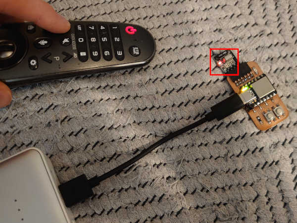
Then I pressed the button 1 on my board to save this command (The IR receiver can read the signals all the time).
And after turning on the TV with the remote, I pressed and held the button 2 on my board to increase volume.
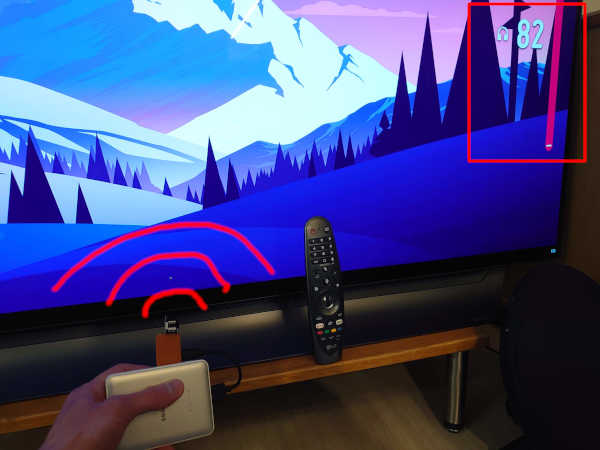
The signal is very weak and has to be really close but it works!
End of week 9.