Final project
Final Project
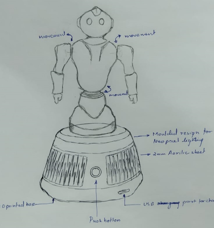
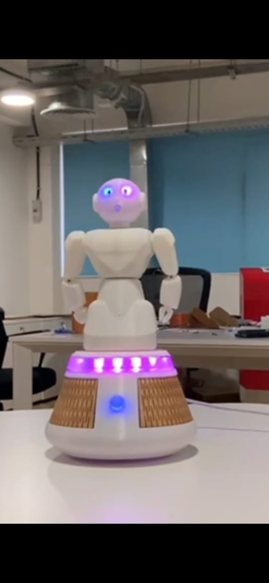
At that moment, I recalled our mentor, Shaeen Palayi, mentioning the design of a similar robot. I decided to search for a relevant design that could serve as a reference. Fortunately, I found an appropriate design and imported an image of it into Fusion 360. Using the image as a guide, I began sketching and incorporating the necessary elements into my own design. This allowed me to overcome the obstacle and proceed with the project.
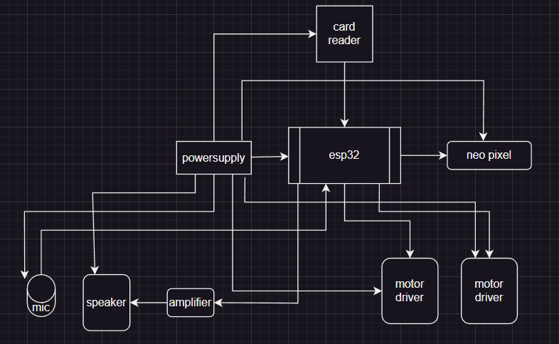
During the 16th week of the Fab Academy, as part of the “Application and Implication” assignment, I created a block diagram of the electronic circuit using an online application called Flow Chart Maker and Line Diagram. This tool allowed me to visualize and plan the overall structure of my circuit by representing it in a block diagram format.
After completing the seventeenth week of the Fab Academy, I proceeded with the design phase of the entire object. During the design process, I utilized various techniques to create the desired shape and structure.
One approach I employed was designing the entire body as a solid block.One approach I employed was designing the entire body as a solid block.
Additionally, I utilized the shell command extensively. This command enabled me to make all the parts of the object hollow.
Fusion Design
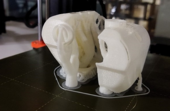
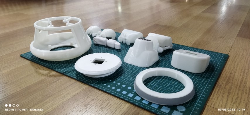
After completing the design phase of the robot, I moved on to the 3D printing process. To ensure ease of assembly and disassembly, I designed the robot parts in a modular manner.
For the assembly of the robot, I incorporated the use of screws in some parts. This allowed for a secure and stable connection between components, ensuring that they would stay in place during operation.
In addition to screws, I also utilized press-fit connections for certain parts.Press-fit connections simplified the assembly process and reduced the number of fasteners required.
By combining both screw-fastened and press-fit connections, I ensured that the robot parts could be easily assembled and disassembled when necessary. This modularity facilitated maintenance, repairs, and potential future modifications to the robot.
3D printing
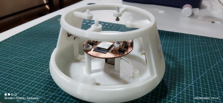
Bottom base
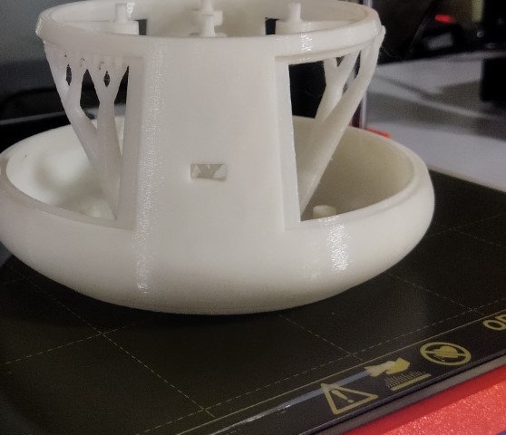
The bottom base of the robot accommodates the main PCB (Printed Circuit Board) and the switch PCB.
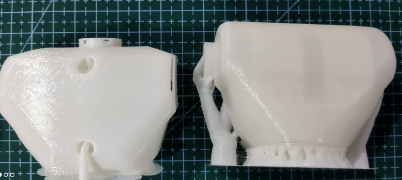
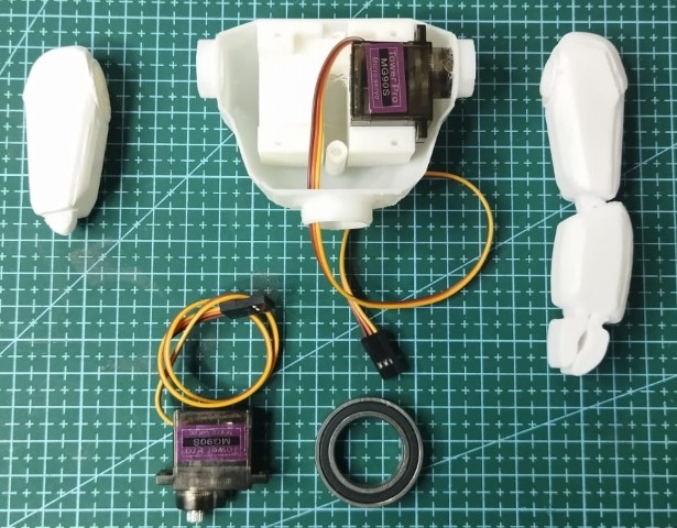
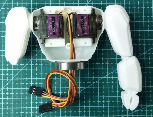
Body
The body part of the project securely holds two servo motors using a clamp mechanism.
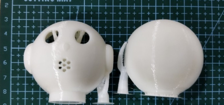
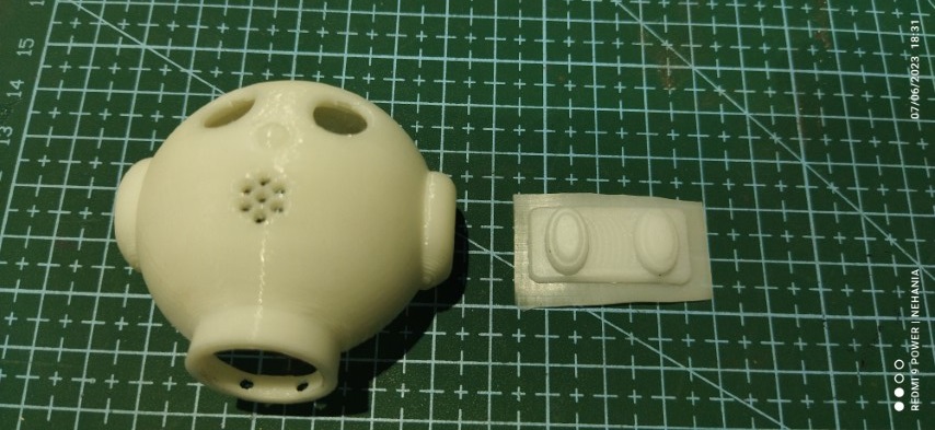
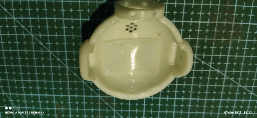
Head
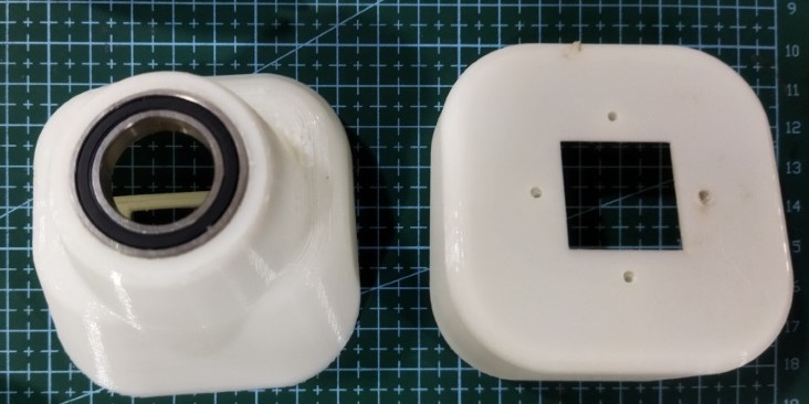
Midpart
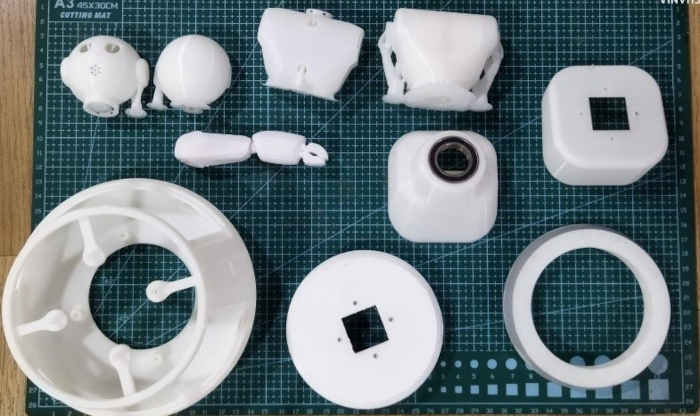
3D printing
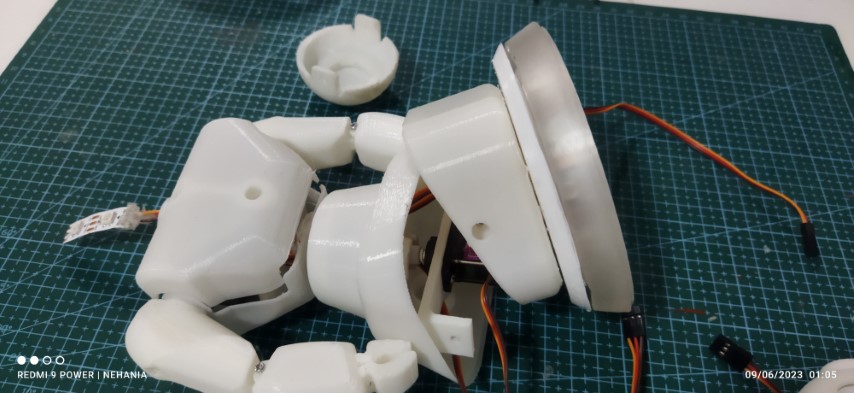
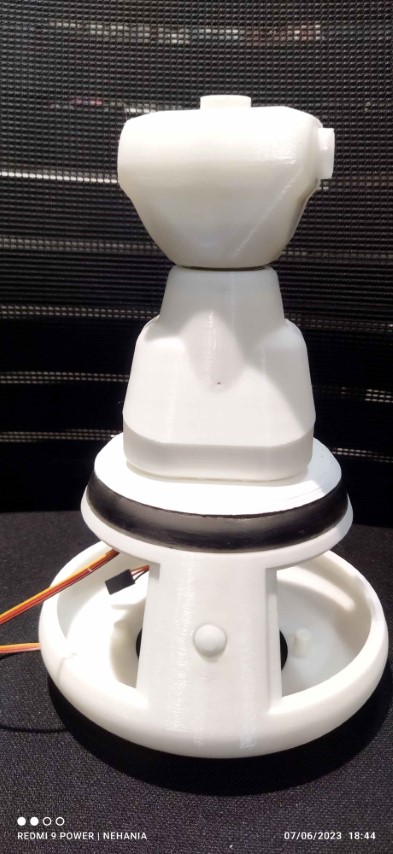
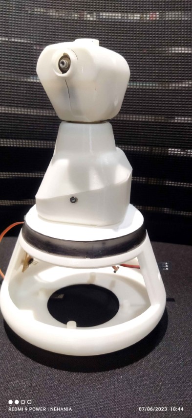
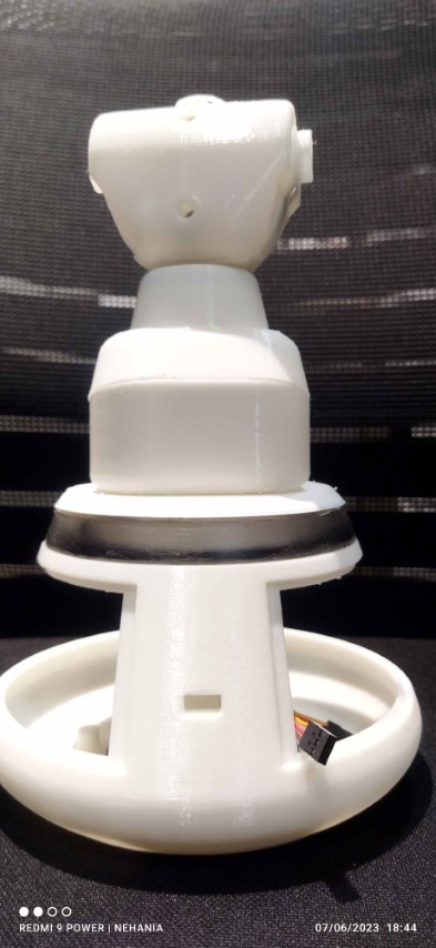
All the parts 3D printed are arranged for test assembly
Casting
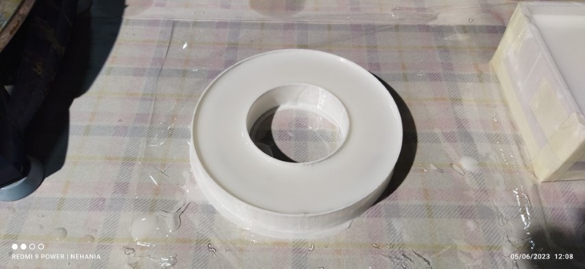
I am now at the stage of casting the mold. I want to ensure that the NeoPixel, located just below the midpart of the robot, is clearly visible. To achieve this, my plan is to cast a resin ring around the NeoPixel, allowing its light to shine through.
![]()
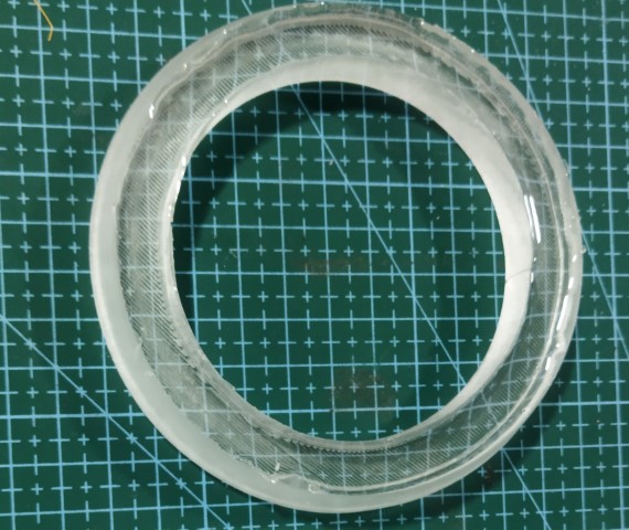
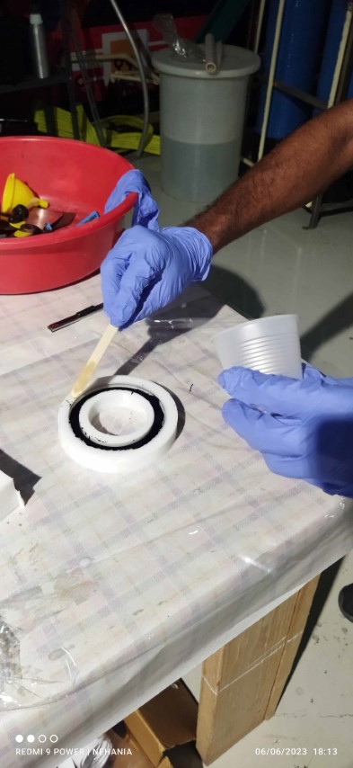
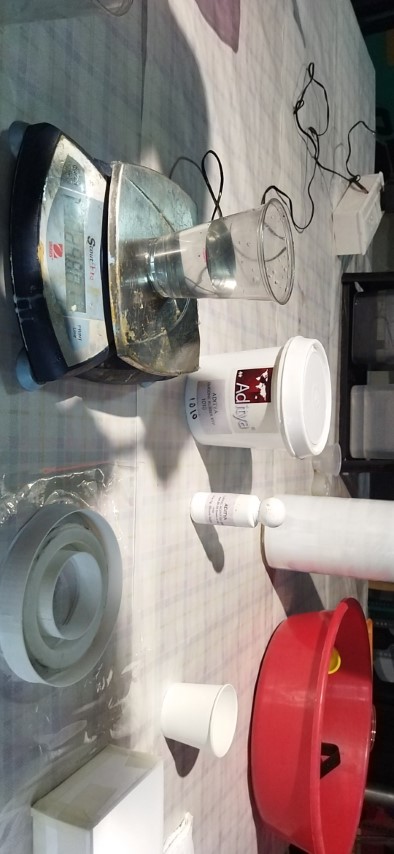
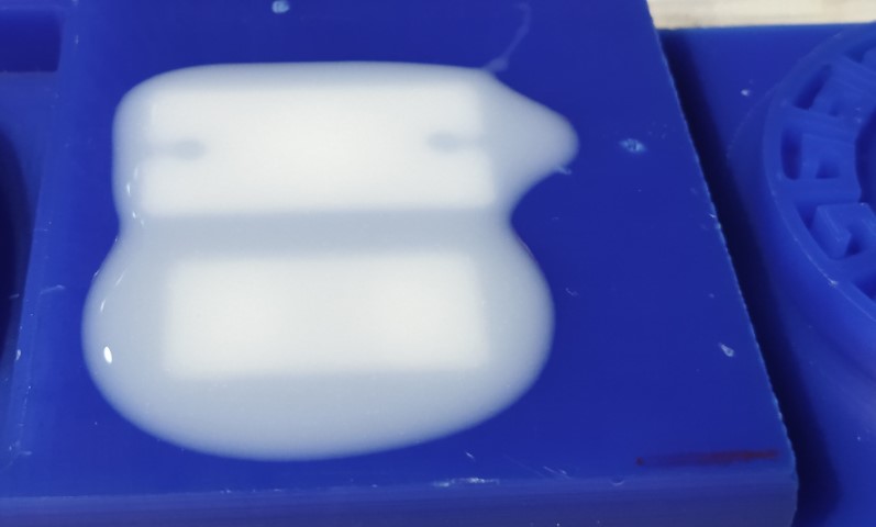
For that I made a 3D printed ring insted of milling.Applies some metal putty to get the surface smooth. After that I made a 3D printed case for pouring the sylicon mould. Keeping the 3D printed ring inside the case and poured the silicon rubber mold. I encountered an issue where the 3D printed ring floated on top of the silicon. However, I am able to find a solution to this problem,I suddenly press the ring with the stick and hold it for some time so that it will stick to the bottom of the case. Unfourtunatly I foget to take the picture. Finaly it works and I got the mold
I casted two resin rings, one with black bottom layer to resist the neo pixel light passing to the base. this was avoided because, the shade highlights and looks odd.So I casted a clear resin ring.

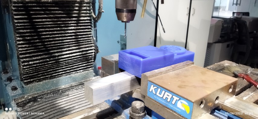
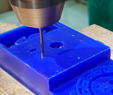
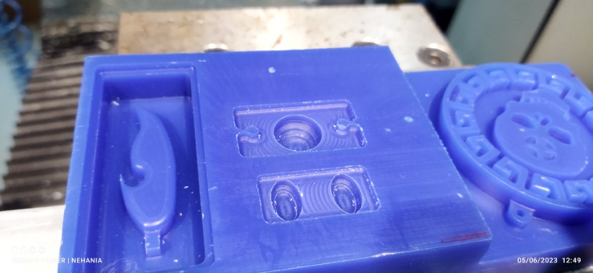
Milling Mold
Now its time to mill the eyes and switch of robot.
Now its time to cast with silicon rubber mixture
Fixing eyes inside the head
Casted slicon eyes pad is cut in to shape and placed inside the head and applied some hot glue.
Same process was repeated in the switch casting. Here O laminated the switch pad in between the switch PCB and bottom case whis is screwed to the base.
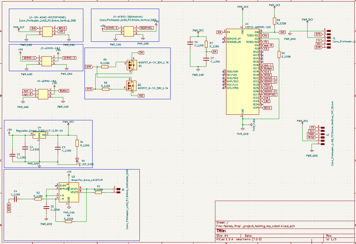
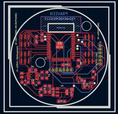
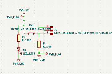
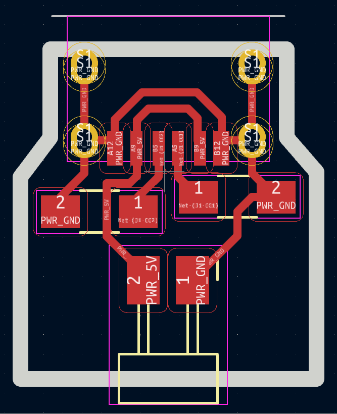
Designing PCB in KiCad
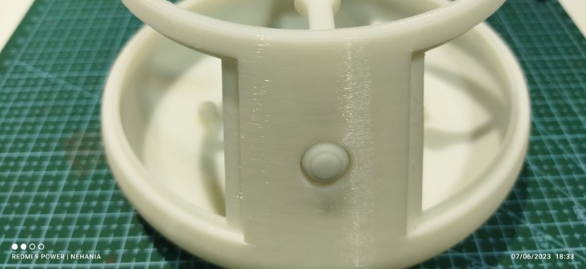
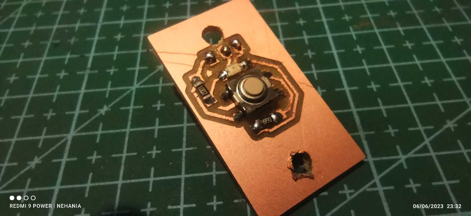
Power switch board
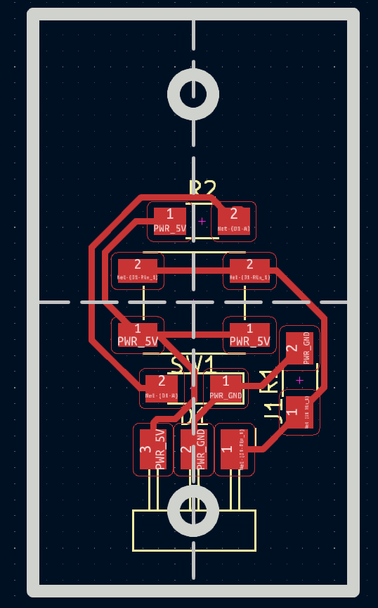
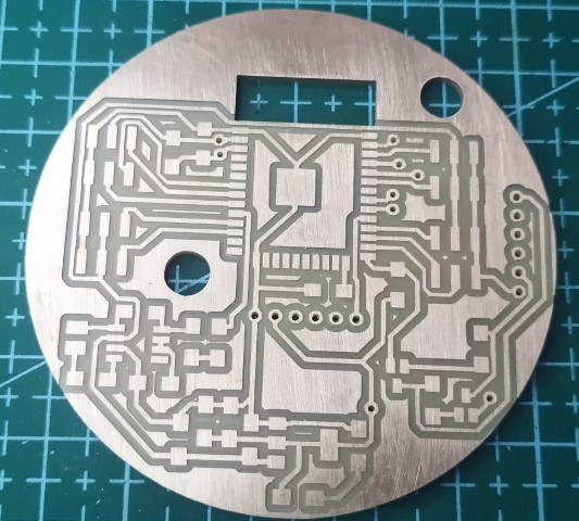
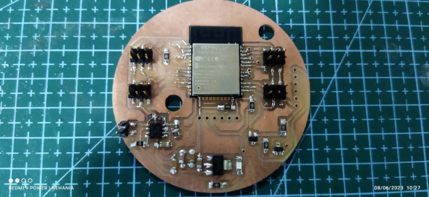
Main Board
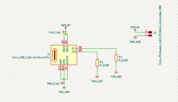
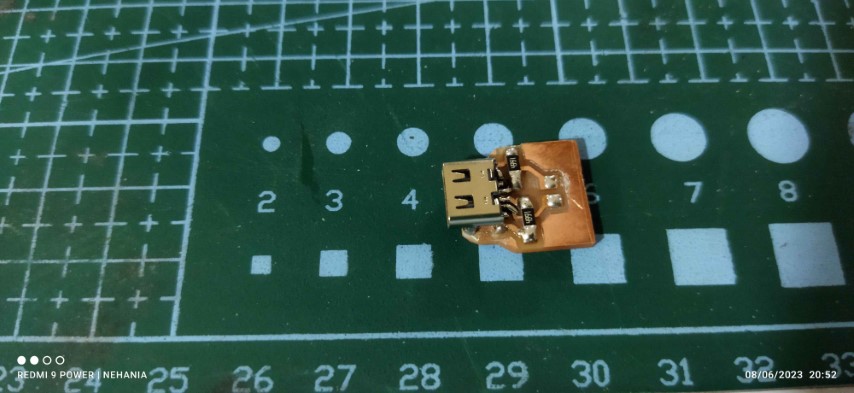
USB C type
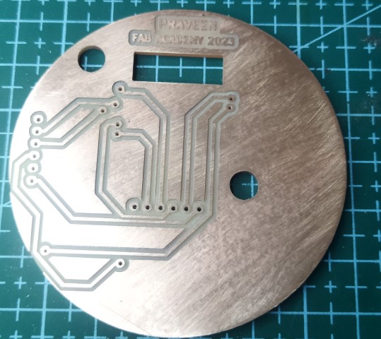
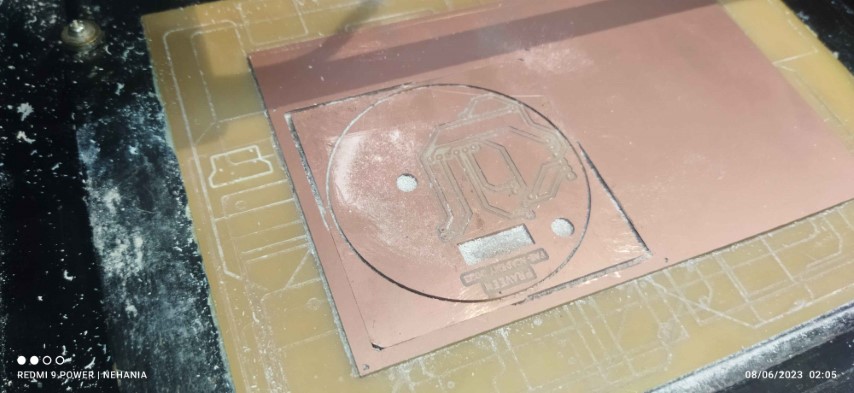
PCB Milling.
Now its time for to mill the PCB. I decided to print three board, one main board and the other for switch and another for fixing the USB C type.

 .
.
BOM
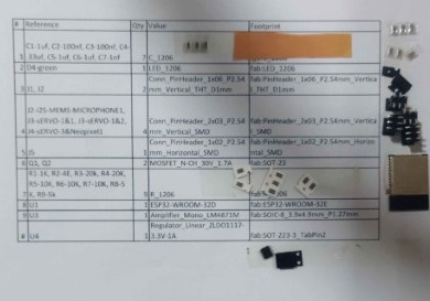
| Sl No | Part Name | Quantity | Price | Total | Source |
|---|---|---|---|---|---|
| 1 | 2mm Black Acrilic sheet | 1’ x 1’ | - | - | Fab Inventory |
| 2 | Neopixel | 250mm | Rs.450 | Rs.450 | Online store |
| 3 | Push Botton | 1nos | - | - | Fab Inventory |
| 4 | ESP 32 Wroom 32 | 1 nos | - | - | Fab Inventory |
| 5 | SPI based SD card reader | 1nos | - | - | Fab Inventory |
| 6 | Speaker3W | 1 nos | - | - | Fab Inventory |
| 7 | Audio amplifier module | 1nos | - | - | Fab Inventory |
| 8 | USB Mini | 1nos | - | - | Fab Inventory |
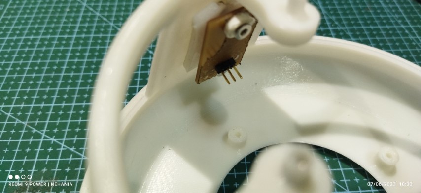
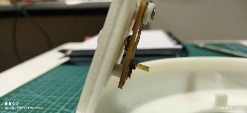
| 9 | 1NMP441 omnidirectional microphone | 1Nos | Rs.267 | Rs.267 | Online |
| 9 | miscellaneous | - | - | - | Fab Inventory |
Soldering
Laser cutting
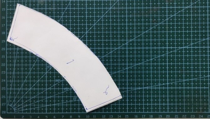
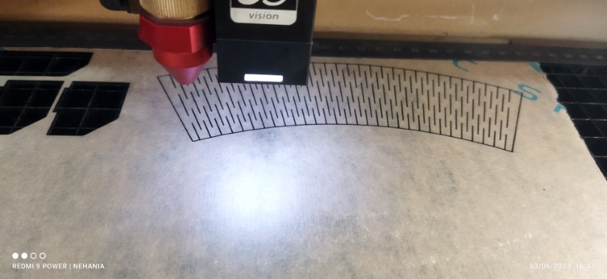
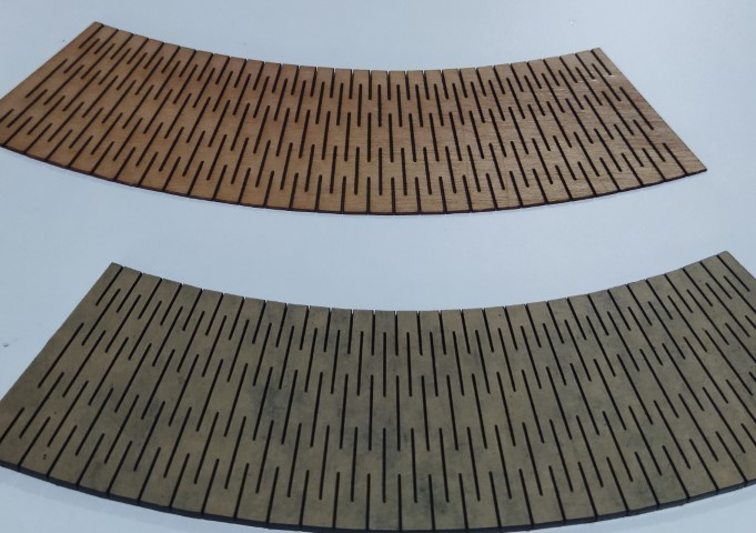
I prefered laser cutting for side panel of robot base. I faces a difficulties for drawing the side panel due to the cone shape. So I develop a sketch tracing from the base and placed over the cutting pad. From here I take the dimension and draw in living hinges in fusion.The dimension of living hinges are made maually. After some trial and error I got the perfect one which fix pefectly.
Assembly
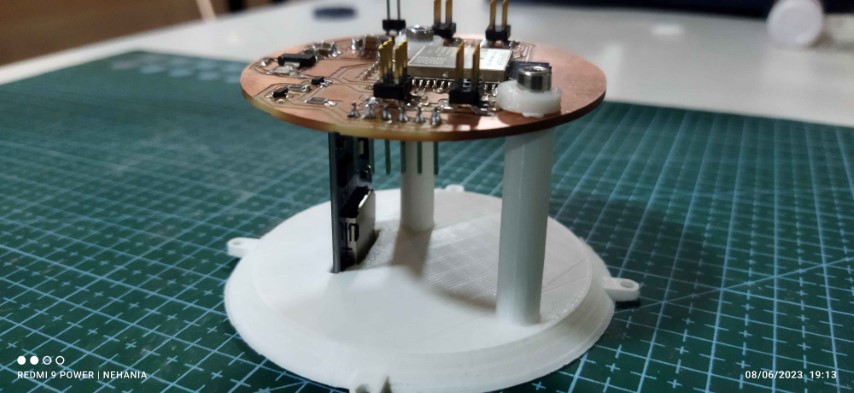
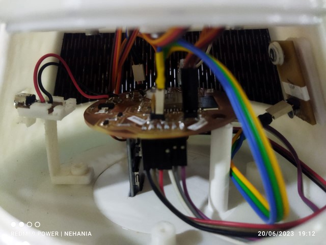
Fixed the main board over the bottom bace cover, whic can be screwed to the base of robot.
Now two servo motors are placed inside the chest of the robot for hand movement.
One servo motor is place inside the midpart for the movement of hip part.
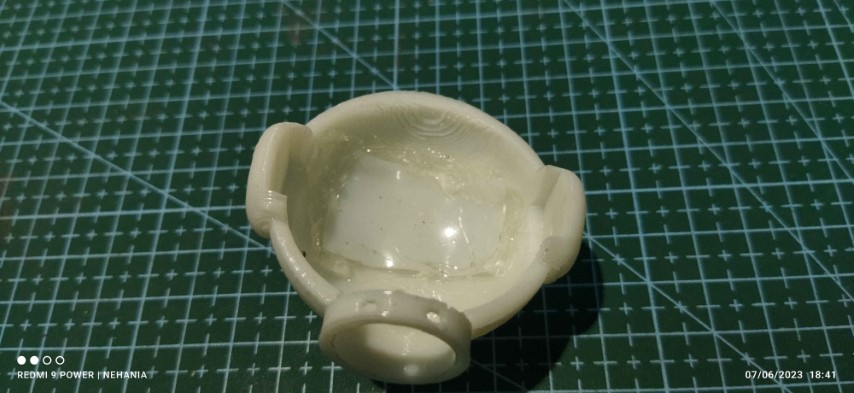
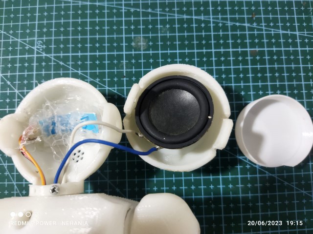
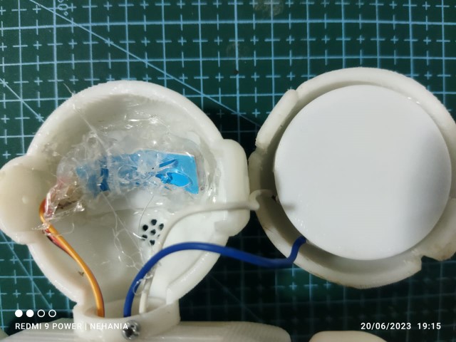
Fixing the speaker and neo pixel inside the head. Neo pixel is place at the back of the eyes pad and hot glued. there is a cavity for acoomadating the speaker and I placed a cap over the speaker to get a clear sound.
Below inage showing the wires connecting to power switch and USB port.
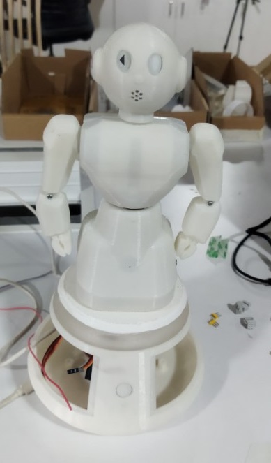
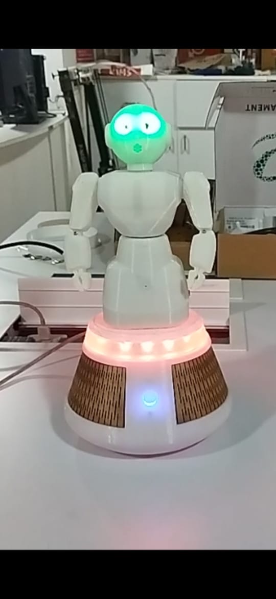
Below images are the semi test assembly, here you can see the black shaded neo pixel ring.The last image show the ring is replaced wiht clear one.
Programming
#include <Wire.h>

//Button
#define button 17
bool bPush = false;
//Neo Pixel LED
#define neoPixel 27

// How many leds in your strip?
#define NUM_LEDS 16

//i2s mic
#define I2S_WS 33
#define I2S_SD 35
#define I2S_SCK 32


//Servo pins
#define leftArm 21
#define rightArm 22
#define waist 26


#include
#include "SoundData.h"
#include "XT_DAC_Audio.h"
#include


Servo LeftArm;
Servo RightArm;
Servo Waist;
int pos = 0;  // variable to store the servo position
int prepos = 1;
bool dir = true;

int period = 1000;
unsigned long time_now = 0;
unsigned long time_early = 0;
unsigned long loop1 = 0;
unsigned long loop2 = 0;
bool dirLED =true;

int count1 =0;
int count2 =0;
    static uint8_t hue = 0;


#define NORMAL_SPEED 1   // These are the playback speeds, change to
#define FAST_SPEED 1.5   // see the effect on the sound sample. 1 is default speed
#define SLOW_SPEED 0.75  // >1 faster, <1 slower, 2 would be twice as fast, 0.5 half as fast

XT_DAC_Audio_Class DacAudio(25, 0);  // Create the main player class object.
// Use GPIO 25, one of the 2 DAC pins and timer 0

XT_Wav_Class WarOfWorlds(WarOfWorldsWav);  // create an object of type XT_Wav_Class that is used by
// the dac audio class (above), passing wav data as parameter.

// SpeedArray contains the order in which the code will playback the sample at the designated speeds
float SpeedArray[] = { NORMAL_SPEED, FAST_SPEED, SLOW_SPEED };
CRGB leds[NUM_LEDS];

void setup() {
  LeftArm.attach(leftArm);
  RightArm.attach(rightArm);
  Waist.attach(waist);
  FastLED.addLeds(leds, NUM_LEDS);
  FastLED.setBrightness(84);
  leds[14] = CRGB(0,255,0);
  leds[15] = CRGB(0,255,0);
  for(int i=0; i<=13; i++)
  {
    leds[i] = CRGB(255,0,0);
  }

  FastLED.show();
}

void fadeall() {


   if(count1<=NUM_LEDS)
   {
     count1++;
   }
   else
   {
     count1=0;
   }
   leds[count1].nscale8(250);

   loop1=time_now;

}

void loop() {

  time_now = millis();

  if (digitalRead(button) && !bPush) {
    bPush = true;
  }

  playMusic(0);

  // if( bPush)
  // {
  //      for (pos = 0; pos <= 180; pos += 1) { // goes from 0 degrees to 180 degrees
  //   // in steps of 1 degree
  //   Waist.write(pos);              // tell servo to go to position in variable 'pos'
  //   delay(15);                       // waits 15ms for the servo to reach the position
  // }
  // for (pos = 180; pos >= 0; pos -= 1) { // goes from 180 degrees to 0 degrees
  //   Waist.write(pos);              // tell servo to go to position in variable 'pos'
  //   delay(15);                       // waits 15ms for the servo to reach the position
  // }
  // }

  if (pos != prepos) {
    LeftArm.write(pos);
    RightArm.write(180 - pos);
    Waist.write(pos);
    prepos = pos;
  }
}


void playMusic(int speed) {
  DacAudio.FillBuffer();  // Fill the sound buffer with data, required once in your main loop
  if (WarOfWorlds.Playing == false && bPush) {
    WarOfWorlds.Speed = SpeedArray[speed];
    DacAudio.Play(&WarOfWorlds);
  }
  if (WarOfWorlds.Playing == true) {
    Move();
    // cyclon();
    bPush = false;
  }
}

void Move() {
  if ((time_now - time_early) >= 15) {

    if (dir) {
      pos++;

    } else {
      pos--;
    }
    if (pos >= 180) { dir = false; }
    if (pos <= 0) { dir = true; }
    time_early = time_now;
  }
}

void cyclon()
{

    // Now go in the other direction.
 if ((time_now - loop2) >= 10)
 {

   if (dirLED) {
      count2++;

    } else {
      count2--;
    }
  if (count2 >= (NUM_LEDS)-1) { dirLED = false; }
    if (count2 <= (NUM_LEDS)-1) { dirLED = true; }
   leds[count2] = CHSV(hue++, 255, 255);
        // Show the leds
        FastLED.show();
        // now that we've shown the leds, reset the i'th led to black
        // leds[i] = CRGB::Black;
        fadeall();

   loop2=time_now;
 }


}
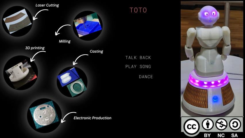
Slide
Video
(Download fusion Design step Files.)
(Download KICad Design Files for main PCB.)
(Download KICad Design Files for power switch PCB.)
(Download KICad Design Files for USB C type PCB.)
licence

This work is licensed under a Creative Commons Attribution-NonCommercial-ShareAlike 4.0 International License.