13. Networking and communications
If various devices and systems to communicate and exchange information with each other , networking and communication protocols are essential. The method of putting these protocols into operation requires developing the software and hardware components that enable thé devices to send, receive, and interpret data in a uniform way.
Individual assignment:
  design, build, and connect wired or wireless node(s)
  with network or bus addresses
Group assignment:
send a message between two projects
Communication
There are several types of communication that are used in electronics and technology, including:
Serial Communication: In serial communication, data is transmitted one bit at a time, over a single wire or channel. Examples of serial communication protocols include UART, SPI, and I2C.
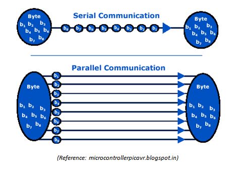
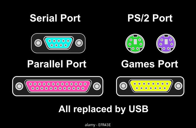
Parallel Communication: In parallel communication, data is transmitted simultaneously over multiple wires or channels. Parallel communication can be faster than serial communication, but it requires more wires and is more susceptible to noise and interference.
Wireless Communication: Wireless communication involves the transmission of data over a wireless medium, such as radio waves, infrared signals, or microwave signals. Examples of wireless communication protocols include Bluetooth, Wi-Fi, and cellular networks.
For this week I am planning to make a communication using nRF24L01 transceiver module.
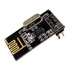
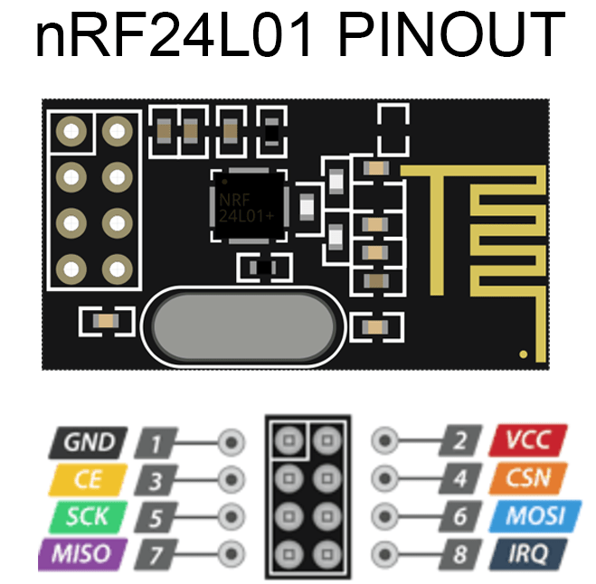
nRF24L01
The nRF24L01 transceiver module is designed to operate in 2.4 GHz worldwide ISM frequency band and uses GFSK modulation for data transmission. The data transfer rate can be one of 250kbps, 1Mbps and 2Mbps.t is commonly used in wireless communication applications such as wireless sensor networks, remote control systems, and wireless mouse and keyboard devices.It can be interfaced with a microcontroller using a SPI interface and has a range of up to 100 meters in open space.
The nRF24L01+ transceiver module works by transmitting and receiving data wirelessly using radio frequencies in the 2.4 GHz band. The module consists of a radio transceiver, a microcontroller, and an antenna.
To transmit data, the microcontroller sends a packet of information to the transceiver. The transceiver then encodes the packet and modulates it onto a carrier frequency in the 2.4 GHz band. The resulting signal is then transmitted via the antenna.
To receive data, the transceiver module listens for incoming signals using its antenna. When a signal is received, the transceiver demodulates it, decodes it, and sends it to the microcontroller. The microcontroller can then process the data and take appropriate actions based on the received information.
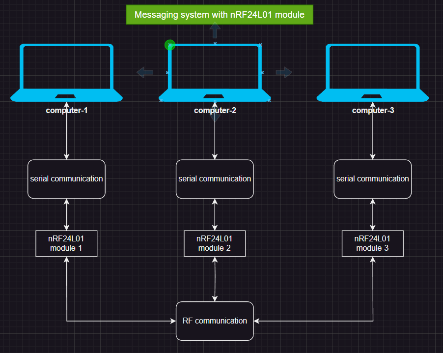
What I want to do is to talk to three boards that are connected to different laptops. So I made three PCB which can connect to nRF24L01 module so that every board can be communicated each other. A block diagram shows how this work is shown below.
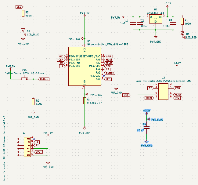
PCB Designing in KiCad
This time I decided to go with ATtiny 1614 microcontroller chip. I made 3nos of board. nRF24L01 transceiver module works in 3.3V. So used a voltage regulator. A botton is connected to trigger the nRF24L01 transceiver module.
Schematic
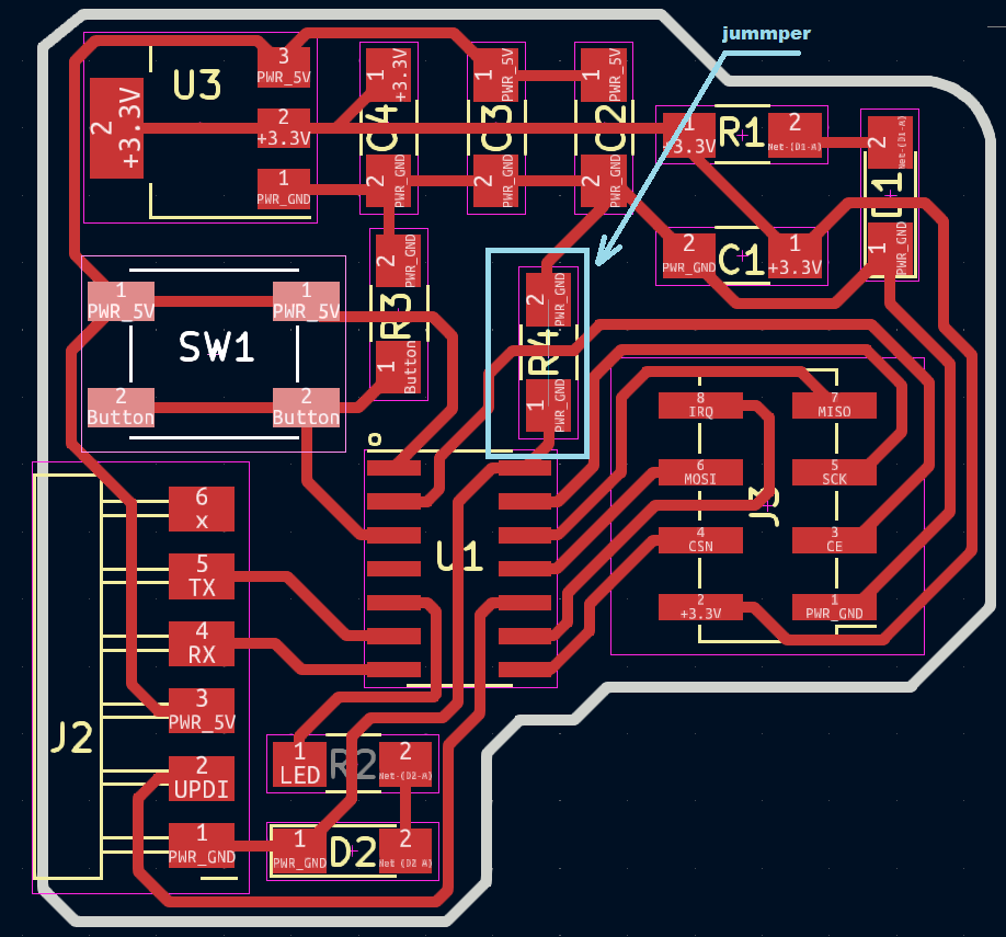
Board Routed
This time I used autorouting method in KiCad.This give me an idea of the routing and later I removed it and redraw manually.Here I used a jummper to avoid collision.
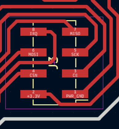
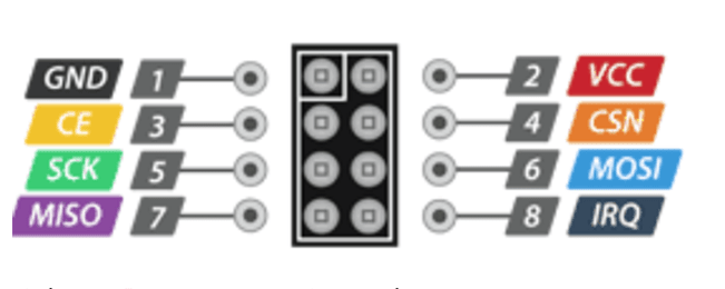
I made a mistake while routing the circuit board. I accidentally reversed the connector pin where the nRF24L01 module connects to the board, causing the antenna to face inward towards the board instead of outward. Please see the board conneter and the piout diagram below.
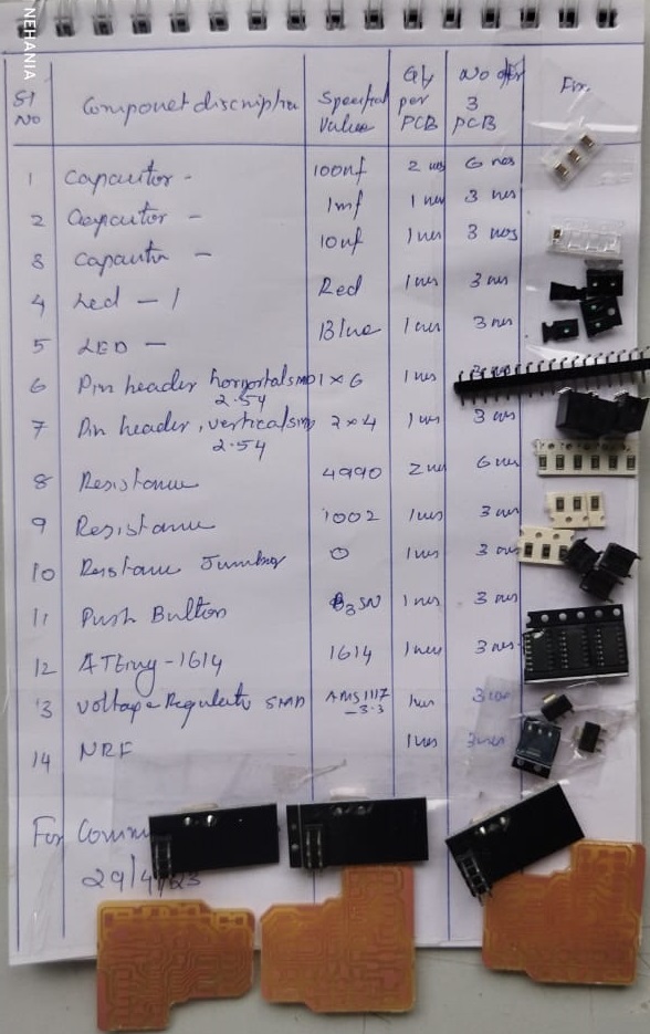
Components
Milled and Soldered the board
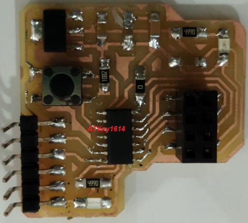
PCB
I had made 3 boards for the communication
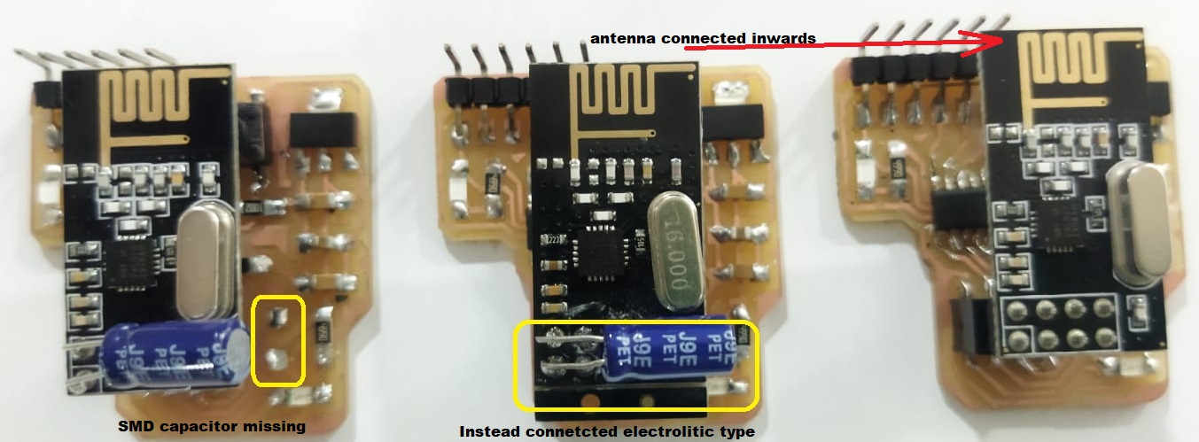
Due to non avaliablilty of SMD type 10mF capacitor in our inventory, I fixed electrolitic type capacitor which is avaliable in our inventory.
Programming Hello World
Programming the board to get “Hello World ” printed in serial printer. My computer was connected with both module and sserial printed hello world.
// transmitter Include Libraries

#include SPI.h>
#include nRF24L01.h>
#include RF24.h>

//create an RF24 object
RF24 radio(0, 6);  // CE, CSN

//address through which two modules communicate.
const byte address[6] = "00001";

void setup()
{
  radio.begin();

  //set the address
  radio.openWritingPipe(00001);

  //Set module as transmitter
  radio.stopListening();
}
void loop()
{
  //Send message to receiver
  const char text[] = "Hello World";
  radio.write(&text, sizeof(text));

  delay(1000);
}
//receiver Include Libraries
#include SPI.h>
#include nRF24L01.h>
#include RF24.h>

//create an RF24 object
RF24 radio(0, 6);  // CE, CSN

//address through which two modules communicate.
const byte address[6] = "00001";

void setup()
{
  while (!Serial);
    Serial.begin(9600);

  radio.begin();

  //set the address
  radio.openReadingPipe(0, 00001);

  //Set module as receiver
  radio.startListening();
}

void loop()
{
  //Read the data if available in buffer
  if (radio.available())
  {
    char text[32] = {0};
    radio.read(&text, sizeof(text));
    Serial.println(text);
  }
}
Communication via nRF24L01
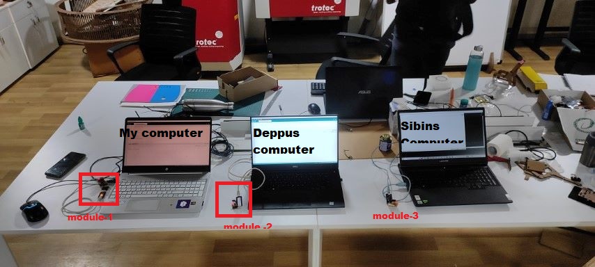
Now I prepared a set up to communicate with my friend Sibin, Deepu and myself computer. All three computers are connected with nRF24L01 transceiver module.
Triggering
Deepu triggered by pressing the button.The term “triggering” means, which send messages from one nRF24L01+ transceiver module to the other when the button is pressed so as to test the communication between the two modules.In my case i made it successfully. Here I face some difficultly in pressing the button, because the button I place comes under the RF module, which I mentioned in earlier paragraph.
In the below video you can see the serial communication done with computer to pcb and from pcb to other pcb by using RF.
//Include Libraries
#include  SPI.h >
#include  nRF24L01.h >
#include  RF24.h>

#define Button 1
#define Led 3

//address through which two modules communicate.
const byte address1[6] = "00001";
const byte address2[6] = "00002";
const byte address3[6] = "00003";

String Owner= "Preaveen :";
const byte address = address1;

char c;
String s;
//create an RF24 object
RF24 radio(0, 6);  // CE, CSN


bool send= false;

void setup() {
  while (!Serial)
    ;
  Serial.begin(9600);

  radio.begin();

  //Set module as receiver
  radio.openReadingPipe(0, address);
  radio.startListening();
}

void loop() {
  while (Serial.available() > 0) {
    c = Serial.read();
    if(c=='\n')
    {
      sendText(s);
      s="";
    }
    else
    {
      s = s + c;
    }

  }

 if(digitalRead(Button)== HIGH)
    {
      sendText("1Button triggerd");
      delay(100);
      sendText("3Button triggerd");
      delay(100);
    }


  if (radio.available() > 0) {

    char text[32] = { 0 };
    radio.read(&text, sizeof(text));
    Serial.println(text);

     digitalWrite(Led,HIGH);
      delay(200);
       digitalWrite(Led,LOW);
      delay(200);
       digitalWrite(Led,HIGH);
      delay(200);
       digitalWrite(Led,LOW);

  }

  delay(1000);
}

void sendText(String Text) {

char switchInput=Text[0];
  switch(switchInput)
  {
    // case '1':
    // send=true;
    // radio.openWritingPipe(address1);
    // break;
    case '2':
    send=true;
    radio.openWritingPipe(address2);
    break;
    case '3':
    send=true;
    radio.openWritingPipe(address3);
    break;

  }

  if(send){
    Text.remove(0, 1);


    radio.stopListening();
    Serial.print(Owner);
    Serial.println(Text);
    char text[32] = "";

    for (byte i = 0; i < Owner.length(); i++) {
      text[i] = Owner[i];
    }


    for (byte i = 0; i < Text.length(); i++) {
      text[(Owner.length()+i)] = Text[i];
    }
    radio.write(&text, sizeof(text));

    radio.openReadingPipe(0, address);

    radio.startListening();
    send = false;
  }
   Text = "";

}
The codes sets up three different addresses that can be used to communicate between two nRF24L01 modules. It defines a sendText() function that takes a string as an argument and sends it over the radio to a specific address. The function is called in the loop() function when a message is received from the serial port or a button is pressed.
The setup() function initializes the serial communication, the nRF24L01 module, and sets the module to listen on the default address.
The loop() function continuously checks for new data on the serial port and sends it over the radio if it receives a newline character. If the button is pressed, it sends two messages over the radio. If a message is received over the radio, it prints the message to the serial monitor and blinks an LED to indicate that a message was received.