9. Output Devices
Objective
Individual assignment: Add an output device to a microcontroller board you’ve designed,and program it to do something.
Group Assignment: Measure the power consumption of an output device. (Group Assignment link.)
Individual Assignment
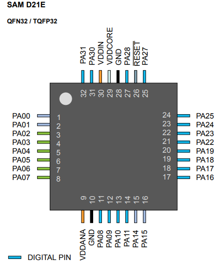
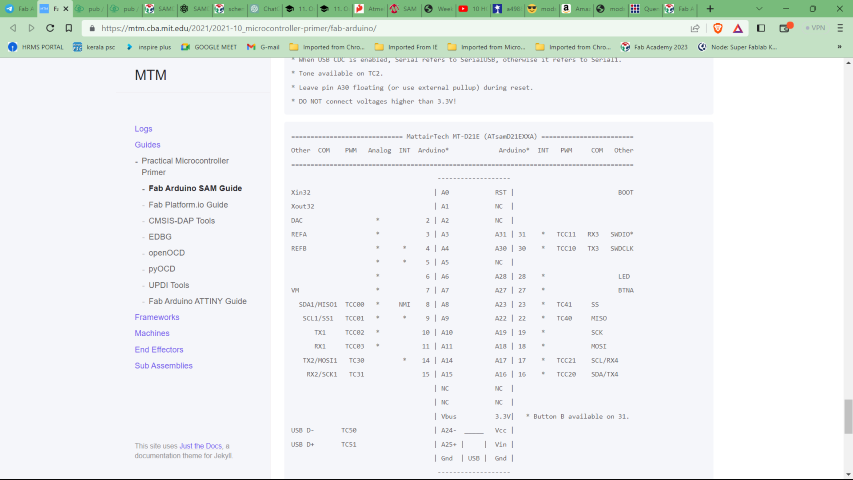
In this week I start to make a microcontroller board using SAMD21E17A controller IC.Pinout diagram show below.(pinout link.)
The SAM D21E microcontroller/ chip is a member of the Atmel/Microchip SAM D21 series. It is based on the ARM Cortex-M0+ 32-bit processor and includes a variety of peripherals, including as UART, SPI, I2C, ADC, DAC, and PWM.
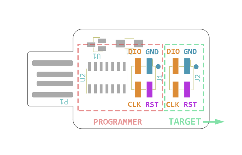
The Programmmer SWD D11C
D11C-based programmer with SWD connector.
My development board
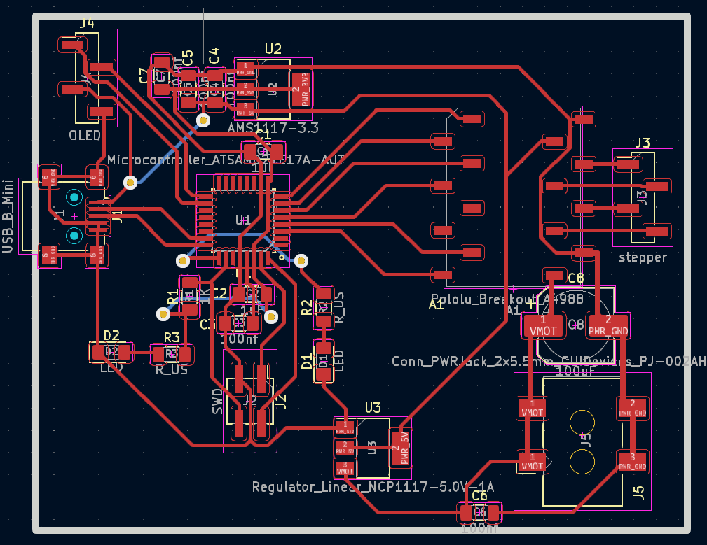
My idea is to create a development board that can interface with various components such as OLED displays and stepper motor.
Here also I choose kicad to design my board.
For stepper motor I used A4988 driver which is avaliable at our fab inventory.
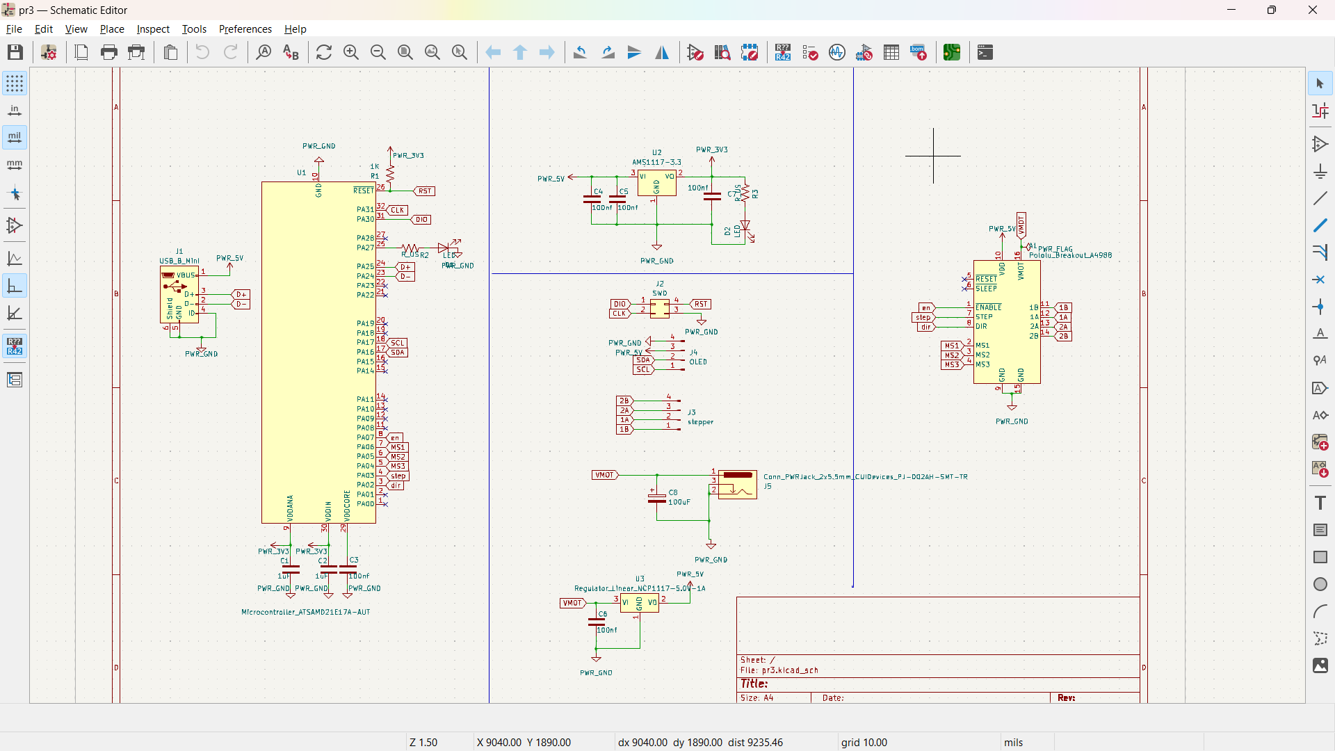
Following is the pin mapping of SAMD 21 for for arduino .
Board PCB
Here I used autotrace option.Three traces are shown as second layer. So I took the wire below the board.
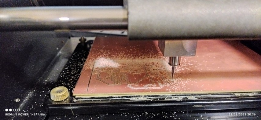
Milling the PCB
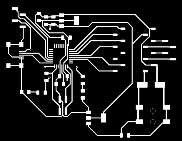
The image was exported from KiCAD and saved as SVG format. Later, the SVG file was edited in GIMP and exported again in PNG format.
Edge Cut
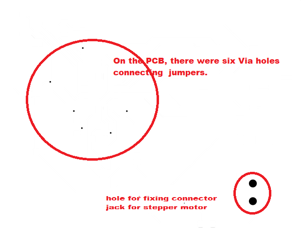
 Via Holes
Traces
PNG file in Fab mods
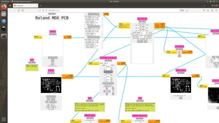
Milling on Roland MDX
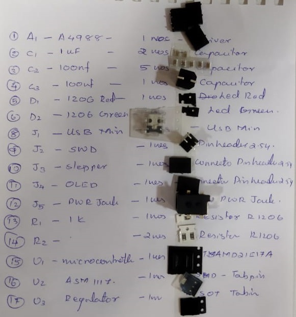
BOM
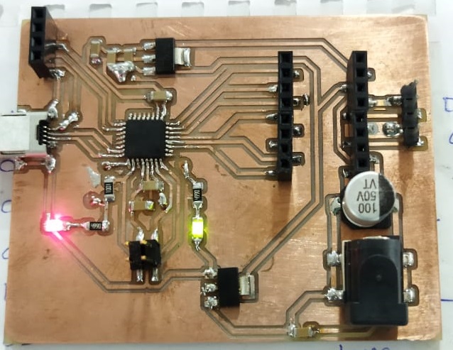
Soldering Components
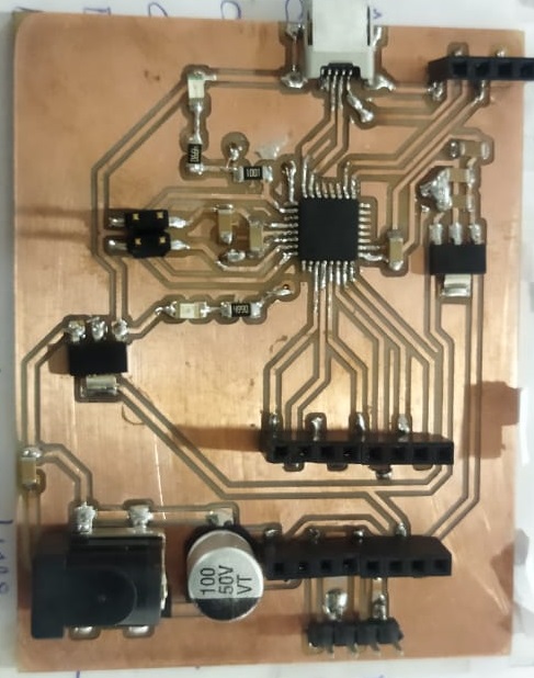
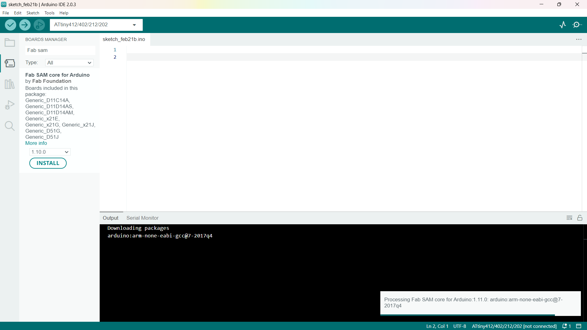
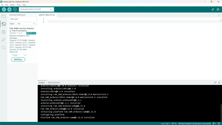
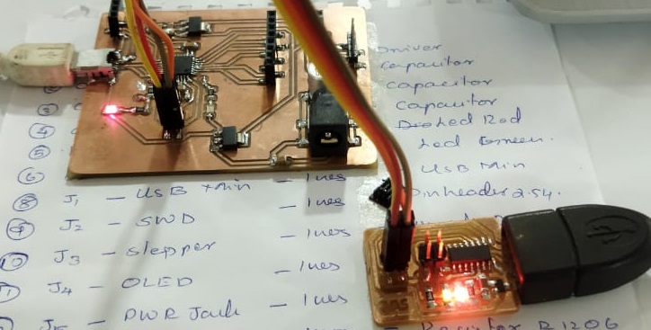
I was able to successfully connect my PCB for programming. I added the official library from Fab to the Arduino IDE and programmed my chip using a programmer that we developed during a group project. To confirm successful programming, I added a power LED to check the power supply to the microchip and an internal LED to verify the programming
Connected the pins to the programmer using F to F jumper wires .
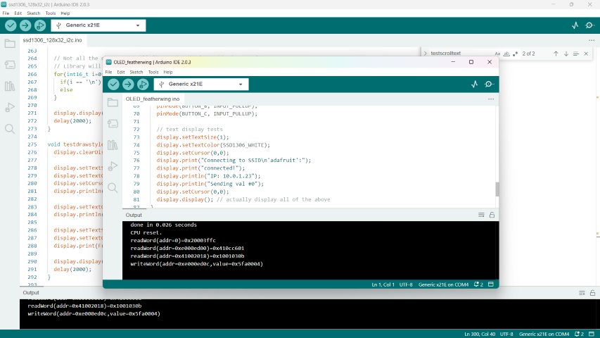
OLED
Adafruit SSD1306 Library
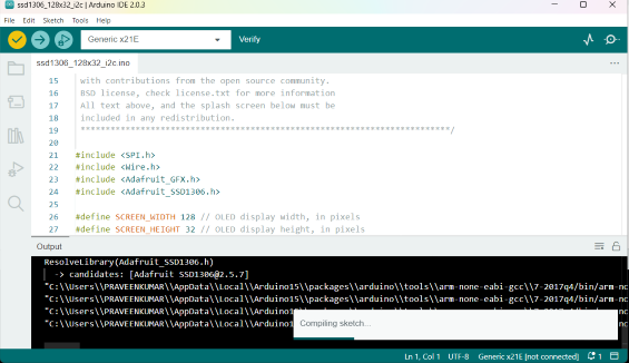
The Adafruit SSD1306 library is used to control OLED displays based on the SSD1306 controller. The SSD1306 controller is commonly found in small monochrome OLED displays with a resolution of 128x64 pixels or 128x32 pixels.
To use the Adafruit SSD1306 library, you need to follow these steps:
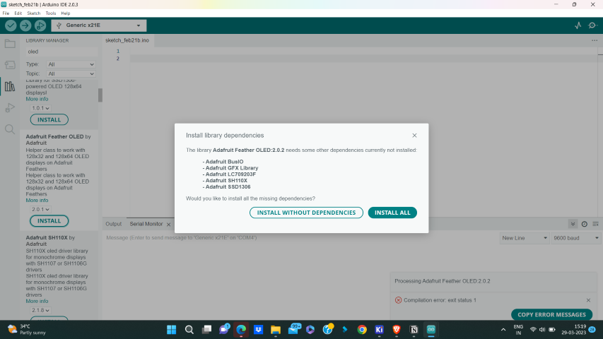
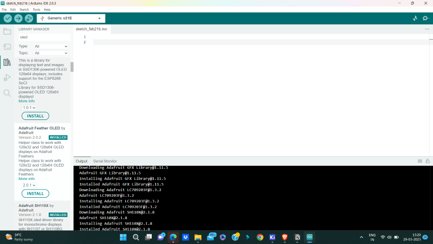
Install the library: Open the Arduino IDE, go to “Sketch” -> “Include Library” -> “Manage Libraries”. In the Library Manager, search for “Adafruit SSD1306” and click the “Install” button to install the library.
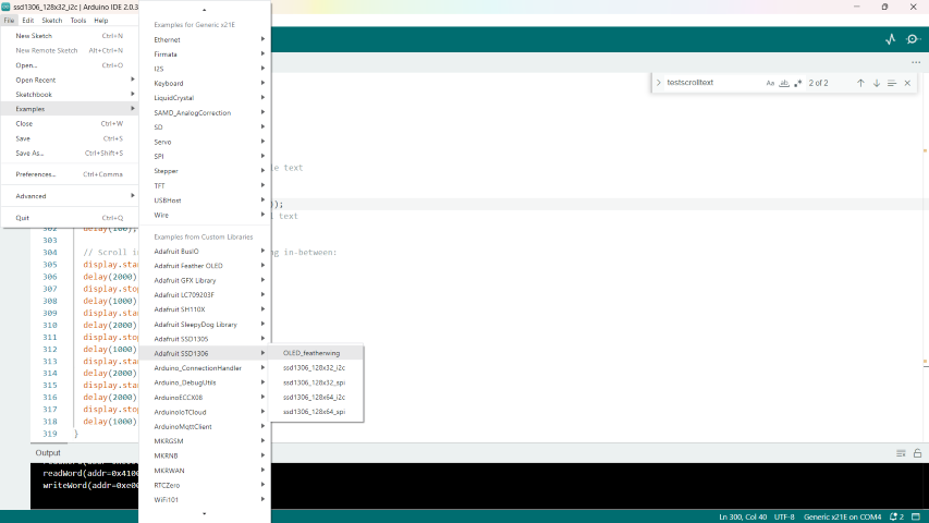
Open an example: Go to “File” -> “Examples” -> “Adafruit SSD1306” to open the library examples. You can select an example that matches your display resolution and desired functionality.
Upload the example: Select the correct Arduino board and port from the “Tools” menu. Then, click the “Upload” button to compile and upload the example code to your Arduino board.