12. Moulding and Casting
Individual assignment:
  Design a mold around the stock and tooling that you'll be using,
     mill it (rough cut + three-axis finish cut),
     and use it to cast parts.
  Extra credit: Use more then two mold parts.
Group assignment:
  Review the safety data sheets for each of your molding and casting materials,then make and compare test casts with each of them
  Extra credit: Try other molding and casting processes.
Let’s Start
I first explore the previous student’s Assignment to get the basic idea for this week assignment.
Designing in Fusion
I Started with a design which I got the idea from Celtic Knot Pendantby VegOilGuy from Ulimaker Thingiverse.
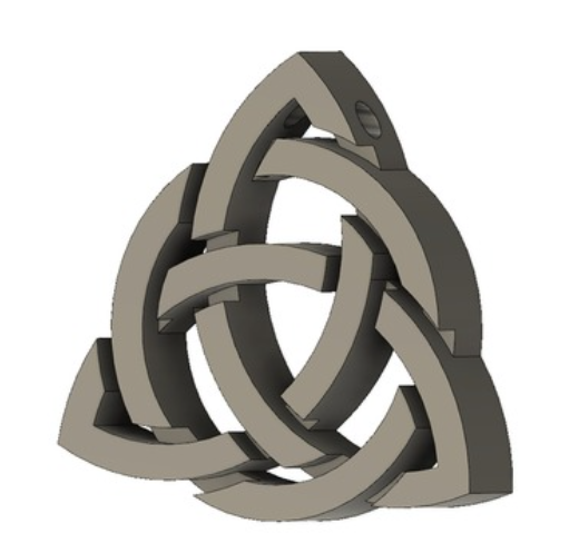
Later, I used Fusion 360 to develop the design as shown below. To prevent 2D projection, additional projection is offered.
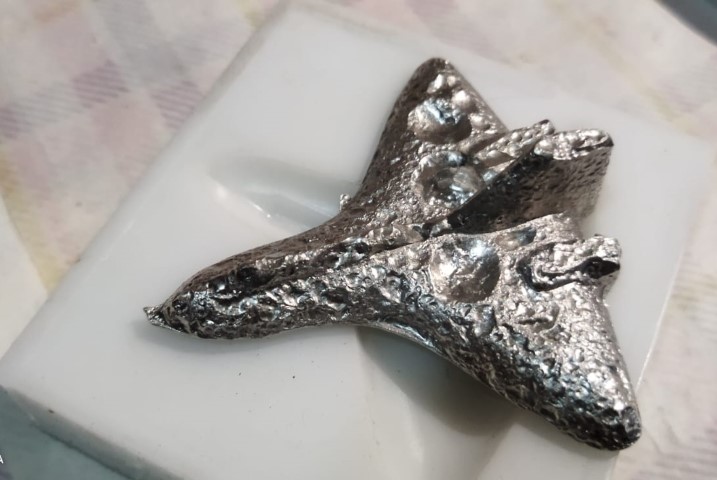
Later when I found my friend Sreyas is doing the drawing of a turbine blade, I switch over to a design of a fighter plane.
CAM
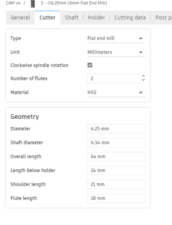
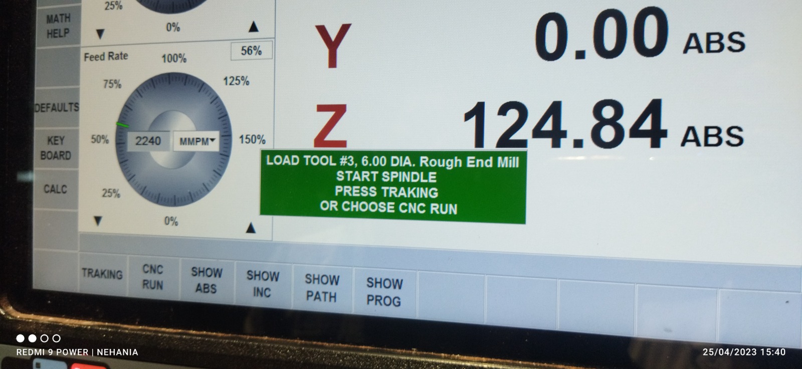
Loading tools in library.
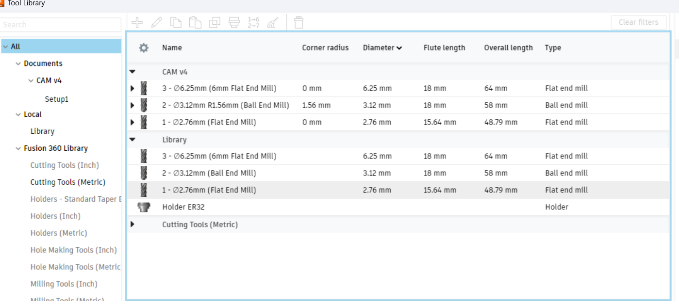
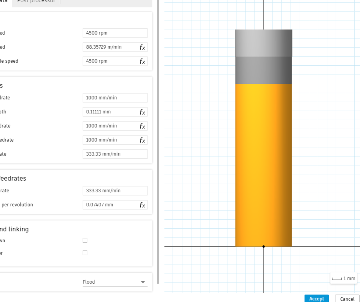
Adding tool spped and feed etc.
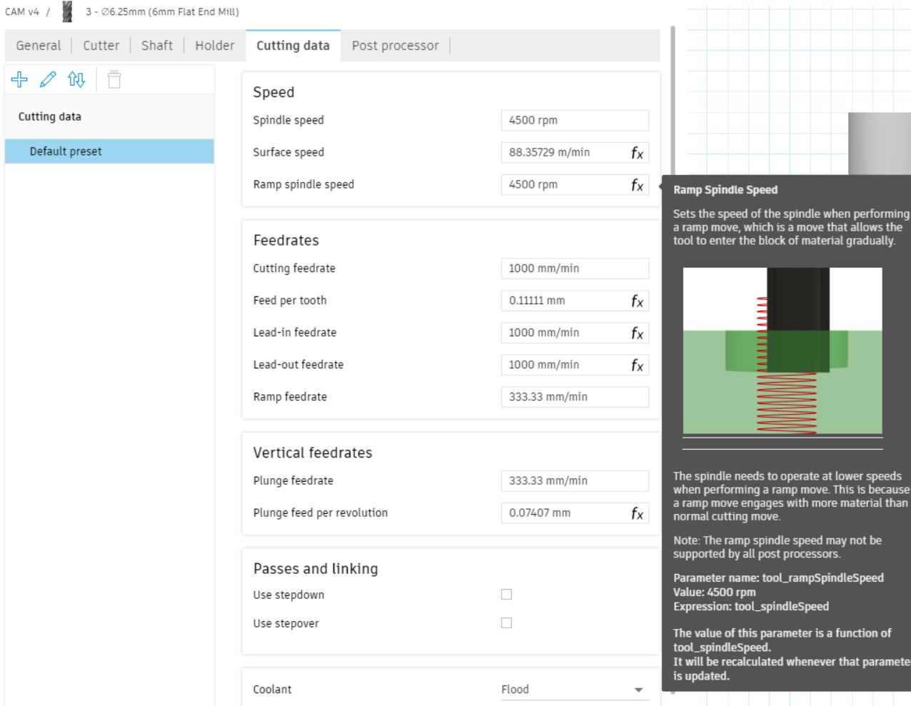
Please accept key proceed further.
First selecting the 3D adaptive clearing for removing large quantity of materials
Second i go for 3D Flat operation that finishes the flat areas.
Then finally I go for scallops operation for finishing the curverd area.
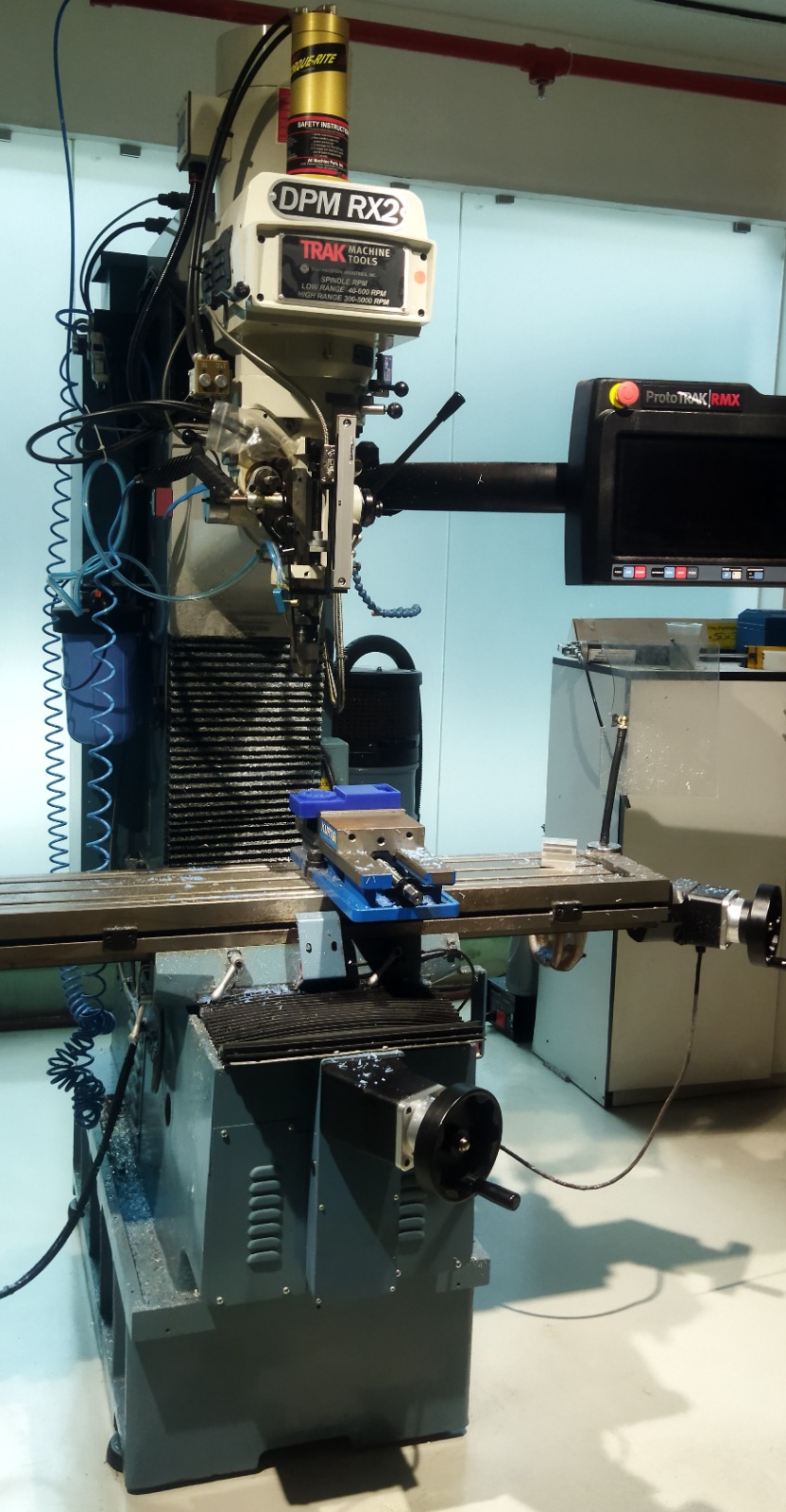
Operational steps for Milling machine DPM RX 2- Vertical Milling Machine are given below.
- Turn on MCB and wait for the machine to boot.
- Long press the reset button on the DRO to enable the controller.
- Place the wax block on the vise
-
Set X, Y origin at the corner of the wax block
-
Go to DRO → JOG
- Remove any tool in the spindle
- Insert the R8 drill chuck in spindle
- Start spindle at 800 rpm
- Zero X-axis
- Approach the wax block from X+ to X- till the edge finder became concentric
- Move the tool about 10 um in to the material and make sure the edge finder dislocatese at the edge
- Bring it 10um back to the original point
- Exit from JOG - press the X button and set the current position as 2(edge finder dia/2) and press the “set absolute” button
- Zero Y-axis
- Approach the wax block from Y- to Y+ till the edge finder became concentric
-
Move the tool about 10 um into to the material and make sure the edge - Find dislocates at the edge
-
Bring it 10um back to the original point
- Exit from JOG - press the Y button and set the current position as -2 (edge finder dia/2) and press “set absolute” button
- Press “program In/Out” → Select 1st GCODE file
- Go to “Tool Table”
- Remove any tool holder/tool in spindle → Press JOG and move the spindle - close to to the base point (Back of vise)
- Exit from JOG → Release the quill and press it against the base →
- Select base → Press “Set absolute ” to set the base point.
- Select the tool for the operation → If not create a new one by specifying the type and diameter
- Insert the tool holder and tool in the spindle → If the newly created tool →Press the tool against the base →Select “Z offset” → Press “Set absolute ” to set the tool offset.
- Set Z origin
- Move to → DRO → JOG
- Jog the tool just above the wax block
- Release the quill and press it against the wax → exit JOG → Press Z → Press “Set absolute ” to set the Z origin.
- Set safe retract → Move tool Z-axis_ a few CM away from the wax block
- Go to setup → select the Z to retract status button → Press “Set absolute ” to set the Z safe to retract height
- Considering the safety of machine and operator It is better to start GCODE Manuel feed
- Go to → “RUN” → “Start” → ”Tracking”→ Press Spindle “REV” → Press “FEED GO”
- Rotate the jog wheel to manually feed the machine (Rotate clockwise to advance in GCODE rotate anticlockwise to travel backward in GCODE) if everything is okey press “FEED STOP”
- Press “CNC Run” → Press “FEED GO”
2nd operation
- Tool Change → raise Z axis → hold hands on the tool holder → release tool by pressing the” tool” out button in the pneumatic control box.
- Insert the new tool
- Press “program In/Out” → Select 2st GCODE file
- Go to “Tool Table”
- Press JOG and move the tool close to the base point (Back of vise)
- select the tool for the operation → If not create a new one by specifying the type and diameter
- Insert the tool holder and tool in the spindle → If the newly created tool →Press the tool against the base →Select “Z offset” → Press “Set absolute ” to set the tool offset.
- Go to → “RUN” → “Start” → ”RUN CNC”→ Press Spindle “FWD” → Press “FEED GO”
- Fix R8 holder in spindle.
- Click on X button and click on jog. and click on spindle on Key
- Rotate the * until (((( kicks on the box.
- Click on Y button and click on jog. and click on spindle on Key
- Rotate the * until (((( kicks on the box.
-
Changing the tool
-
Pull up the z axis, and remove the chuck.
- Go to Tool Library, Click on the **, and touch the spindle on vice and click on Abs set.
- Fix 6 mm flat bit in the holder.
- Then add the detail of the tool in tool Library.
- Click on *** and at that time touch the bit on the top of vice block using jog and handle. and click the Abs set button.
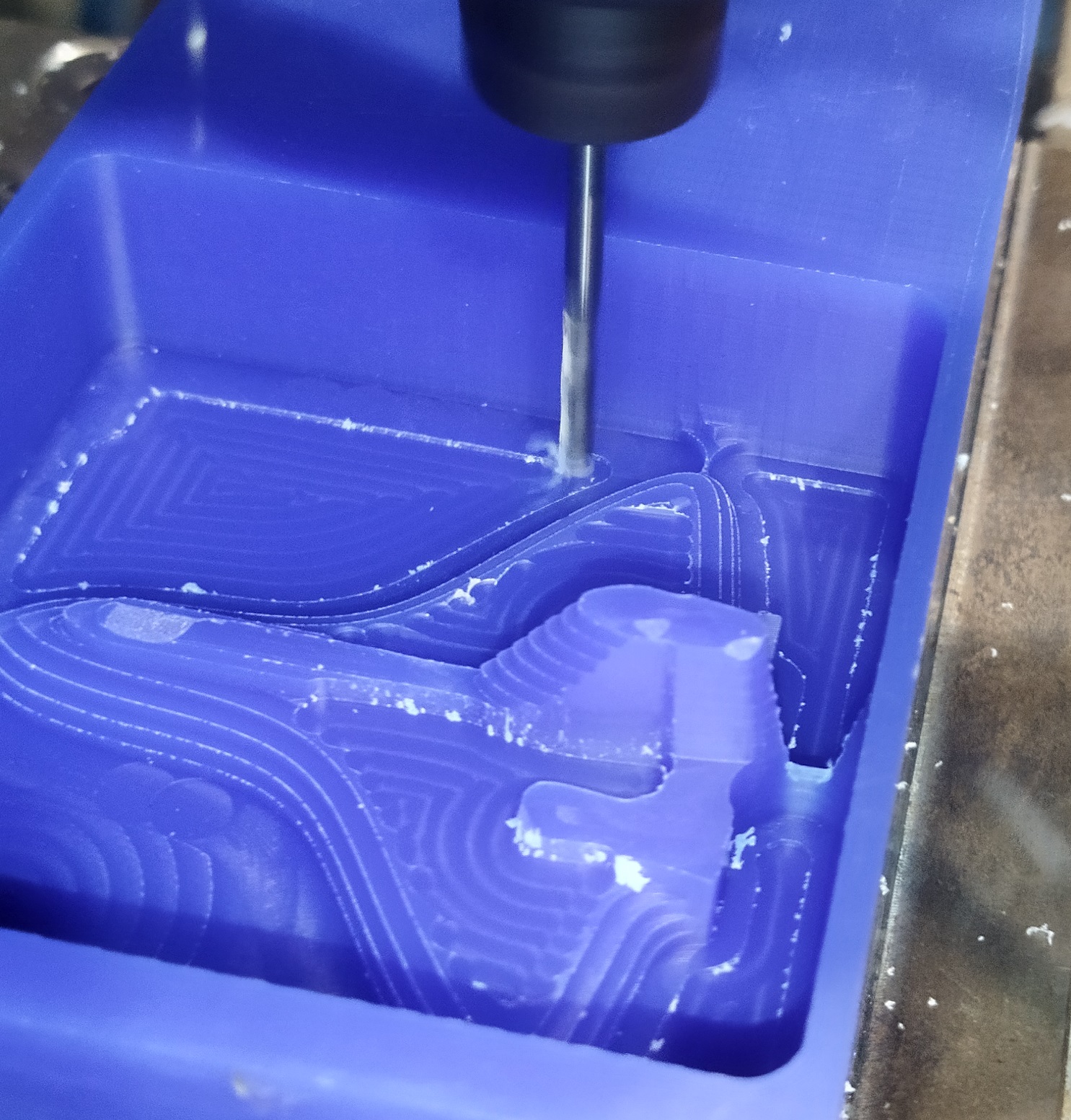
Milling.
- Click on run button.
- Check the tool path by clicking on Toolpath button. We can track the gcode by clicking track button. X spinle is for cafafds and Y spindle is for fine tuning.
Let’s Start the milling
Then I upload the files in the machine using pendrive
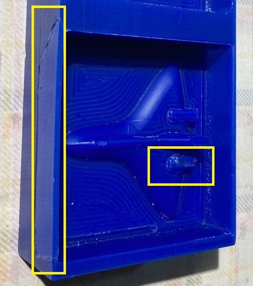
Milling was done wounderfully, but at a stage 3D flat milling by 3mm bit was failed. At that time I fail to notice the machining process, cause I am watching the monitor.When I saw the Stock, it was dislocated from the vice. At that time I couldint able to recognise the exact reason for failure.
Again I started the process from starting using the other end of the block.Here I found during the last seconds of the 3D flat milling, as the tool approches the side bottom edge wall, the tool started to loosen. When I was about to press the emergency stop, the milling tool bit hit the mould and got damaged.
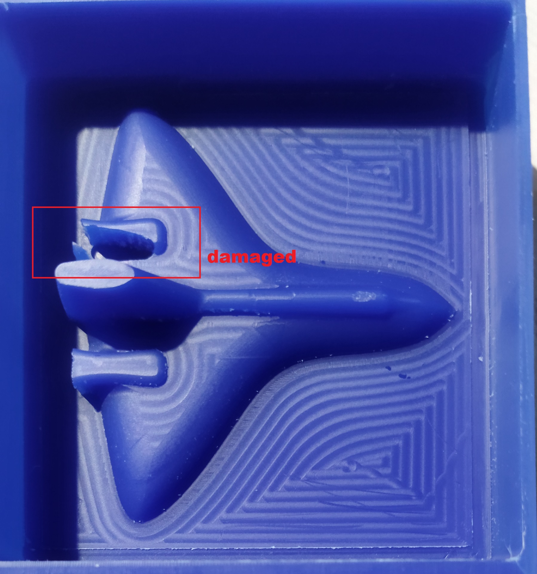
The tool was disengadged due to the complaint in toll holder. Later I replaced it with another one and done the balance process.
Also there was another problem for that. I didnt put enough thickness for the side wall. This causes side wall develepoed cracks. As the toll moves bottom, near to the side wall, the shank of tool touches and sice and the pressure created the tool to disengadge from the tool holder.
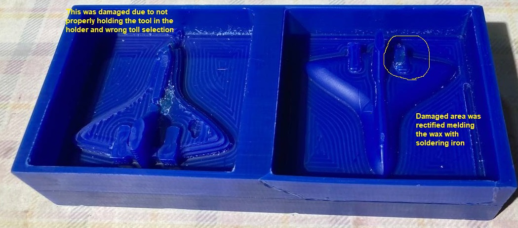
Later I repaired the damage by putting wax and melted with the hot soldering iron.Finaly the positive mould was created.
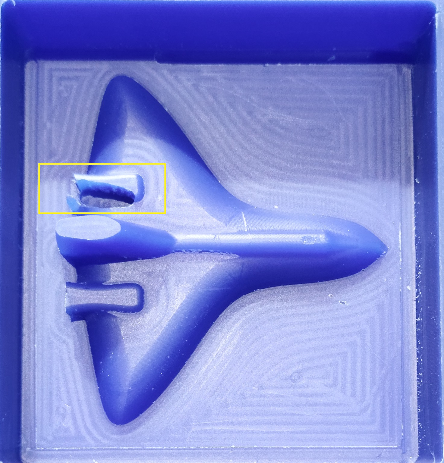
Side edges was also got brocken. This was due to keeping only 2mm thk side wall.
Moulding
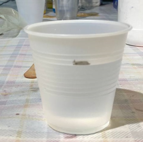
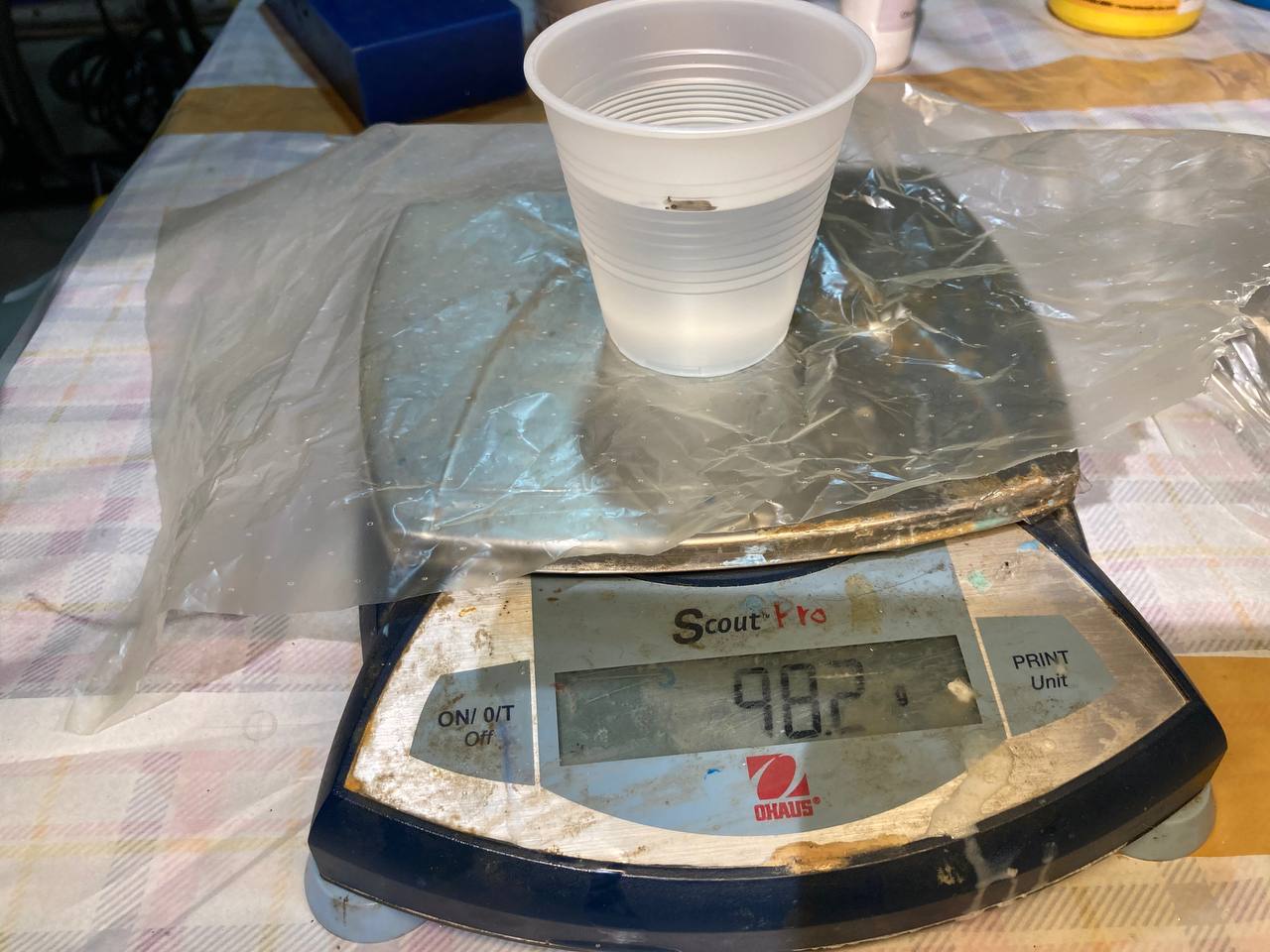
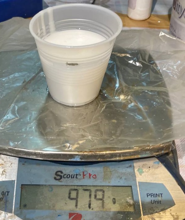
Now its time to make the positive mould. First we have to take the volume of positive mould. For that I filled the mold with water to measure the total volume of the negative side of the wax mold.Marked the volume by a marker over the glass.The took thé weight by a weighing machine. After this I cleaned wax mould by high pressure air to remove all the water particles.
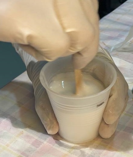
Here I used Adithy brand Silicon rubber and curing agent. The composition is for Silicon rubber 1010 M/gramL used 20-25 ML/gram of harder. In my case I used 97.9ML of silicon rubber and 2.1ML of curing agent.This was properlly mixed slowely to avoid entrapment air bubbles.
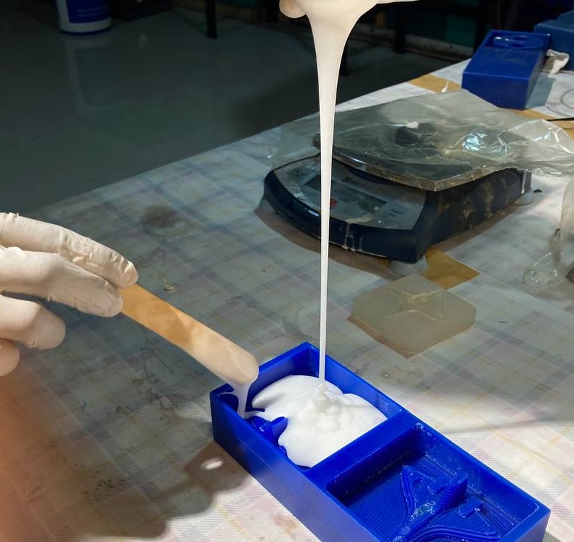
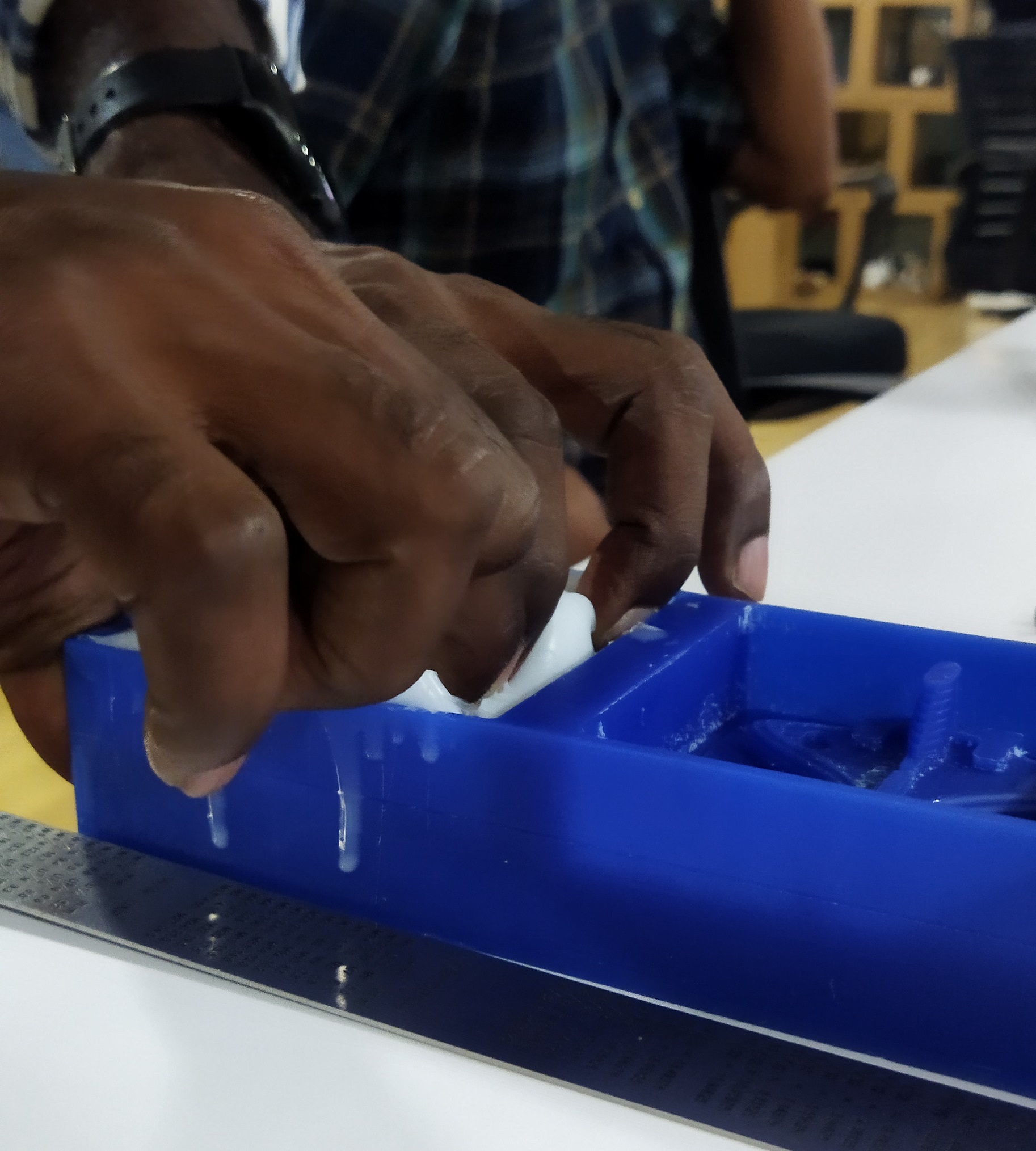
The slicon mixture is added slowly as shown in the image and allow it to solidify.I kept an overnight to set the mould.
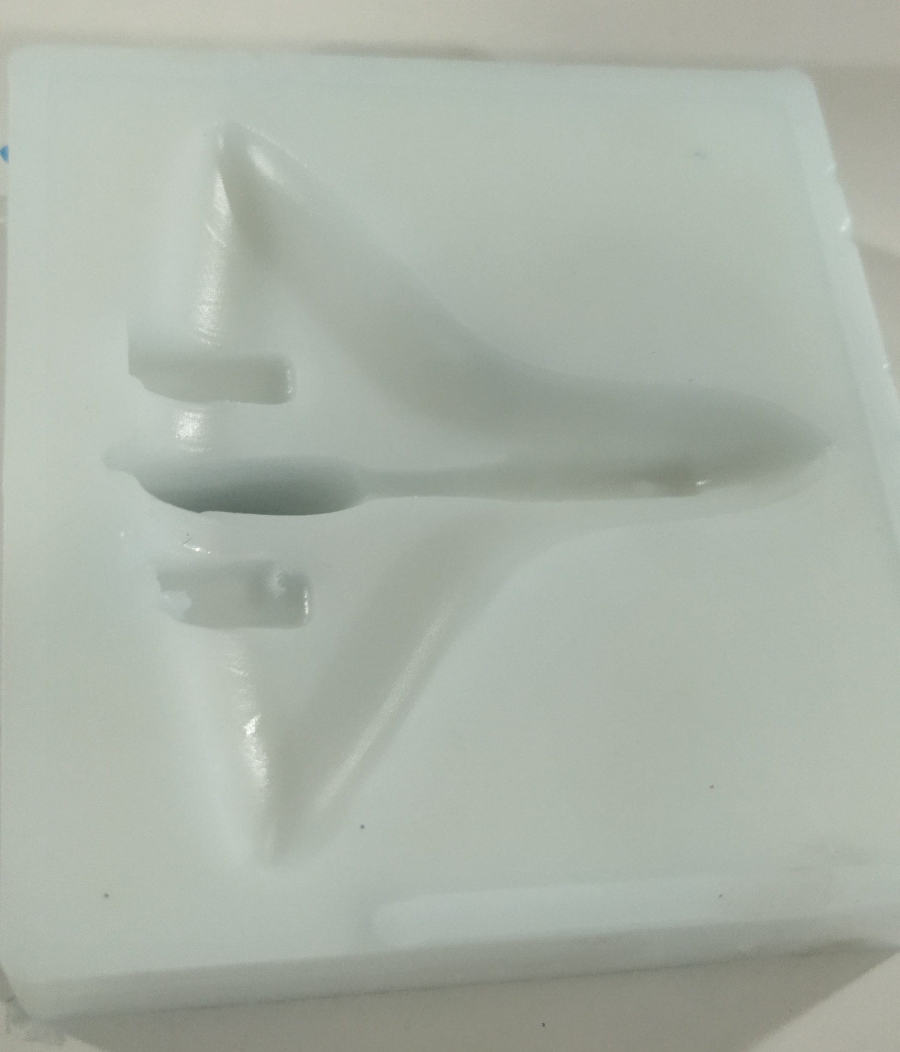
Morning I removed the Silicon mould is from the wax mould.
Casting
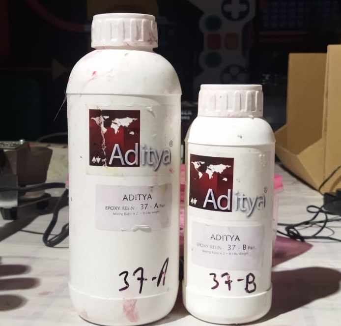
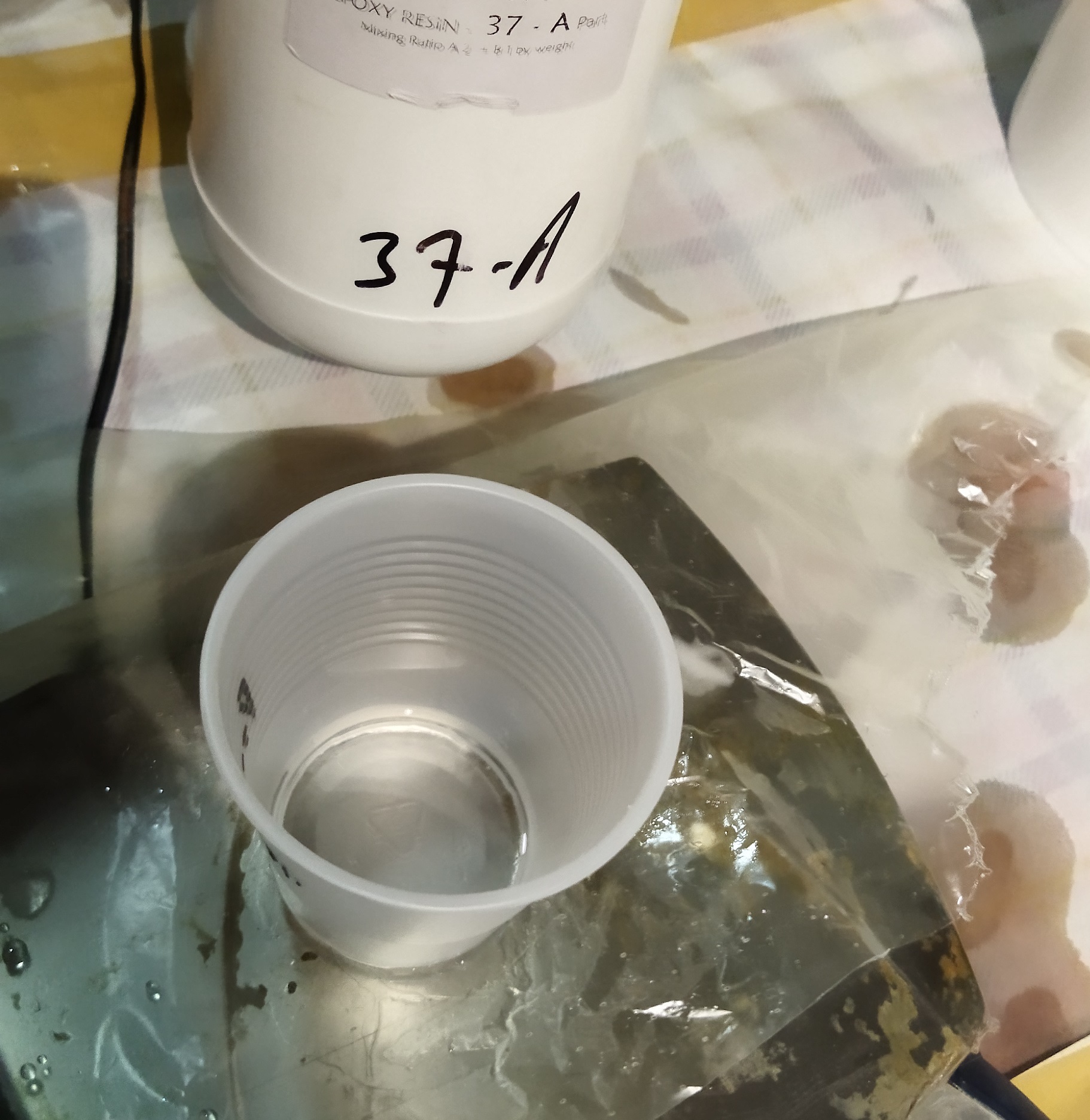
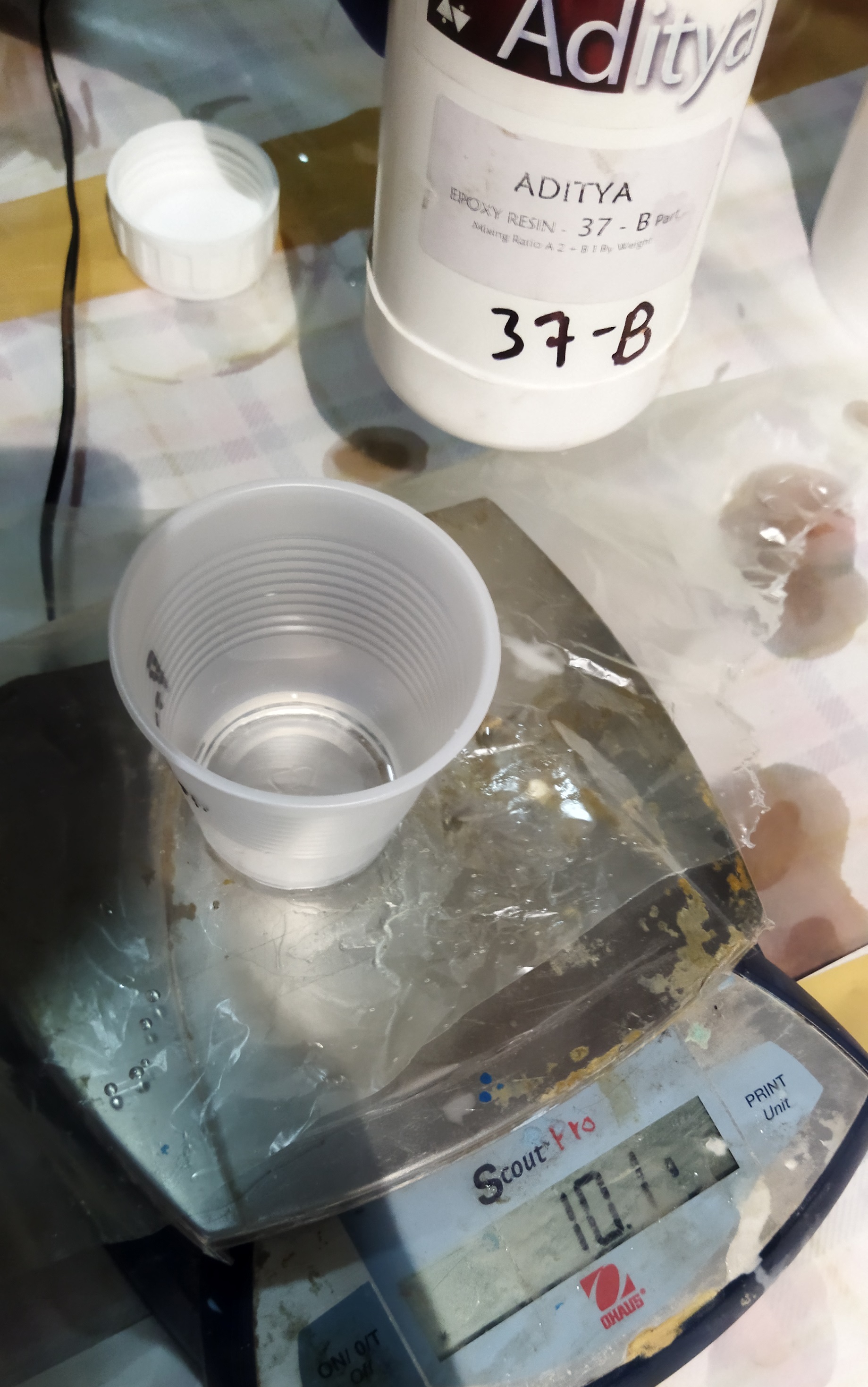
My planning is to cast this mould with Resin. Here we have Adithy brand in our lab. As per the composition Part B must be half the qualtity of Part A.
Here also I have to take the volume of cast and marked and weight as mentioned above in the silicon mould.
Part A and part B is mixed throughly and slowely to avoid air bubbles entrapment.
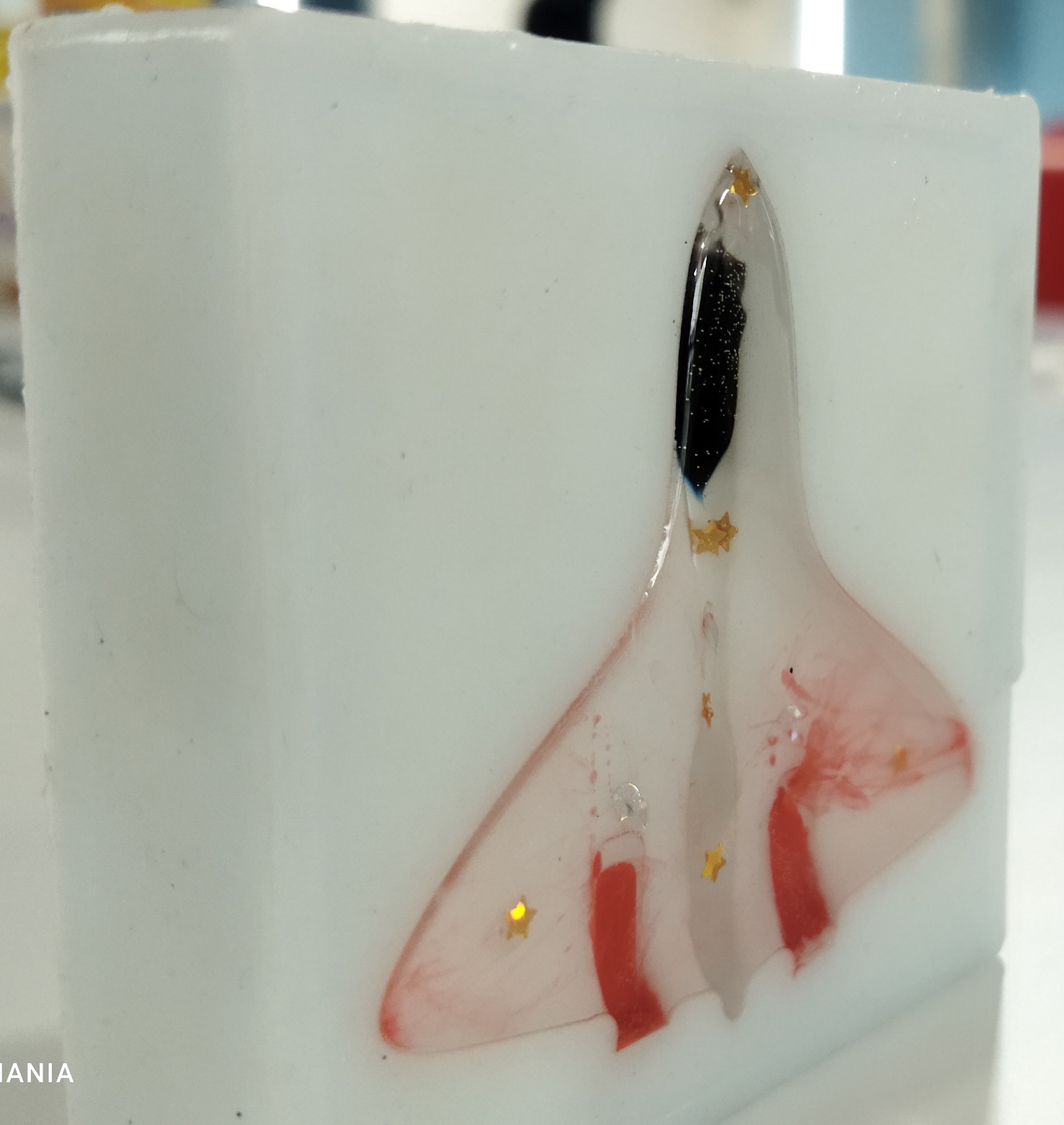
Then I poured in to the mould cavity. Allow it to solidify the compound. I kept it a fornight.
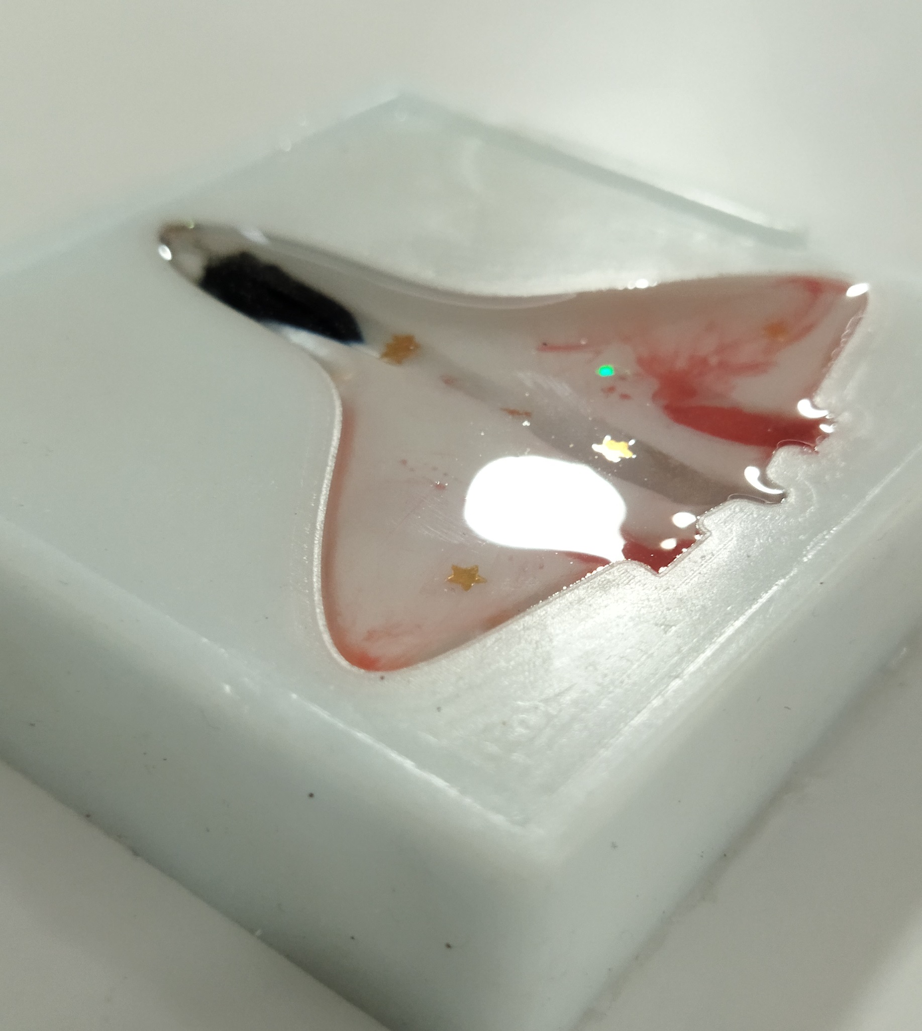
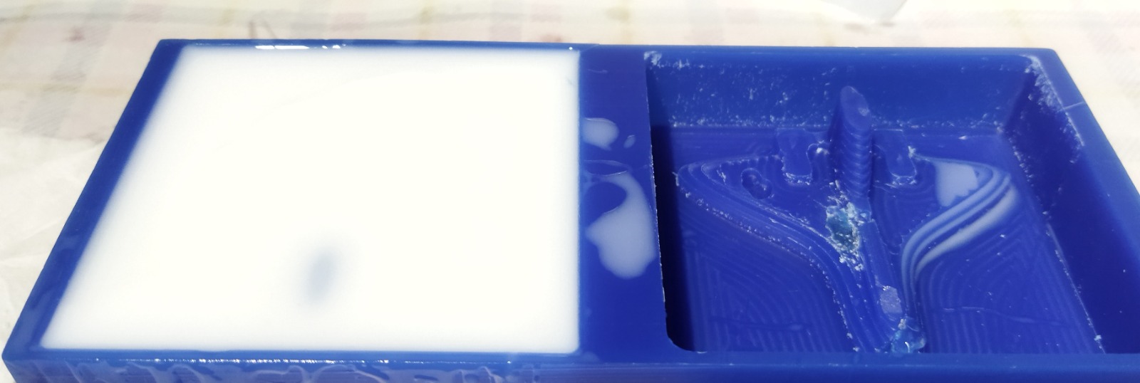
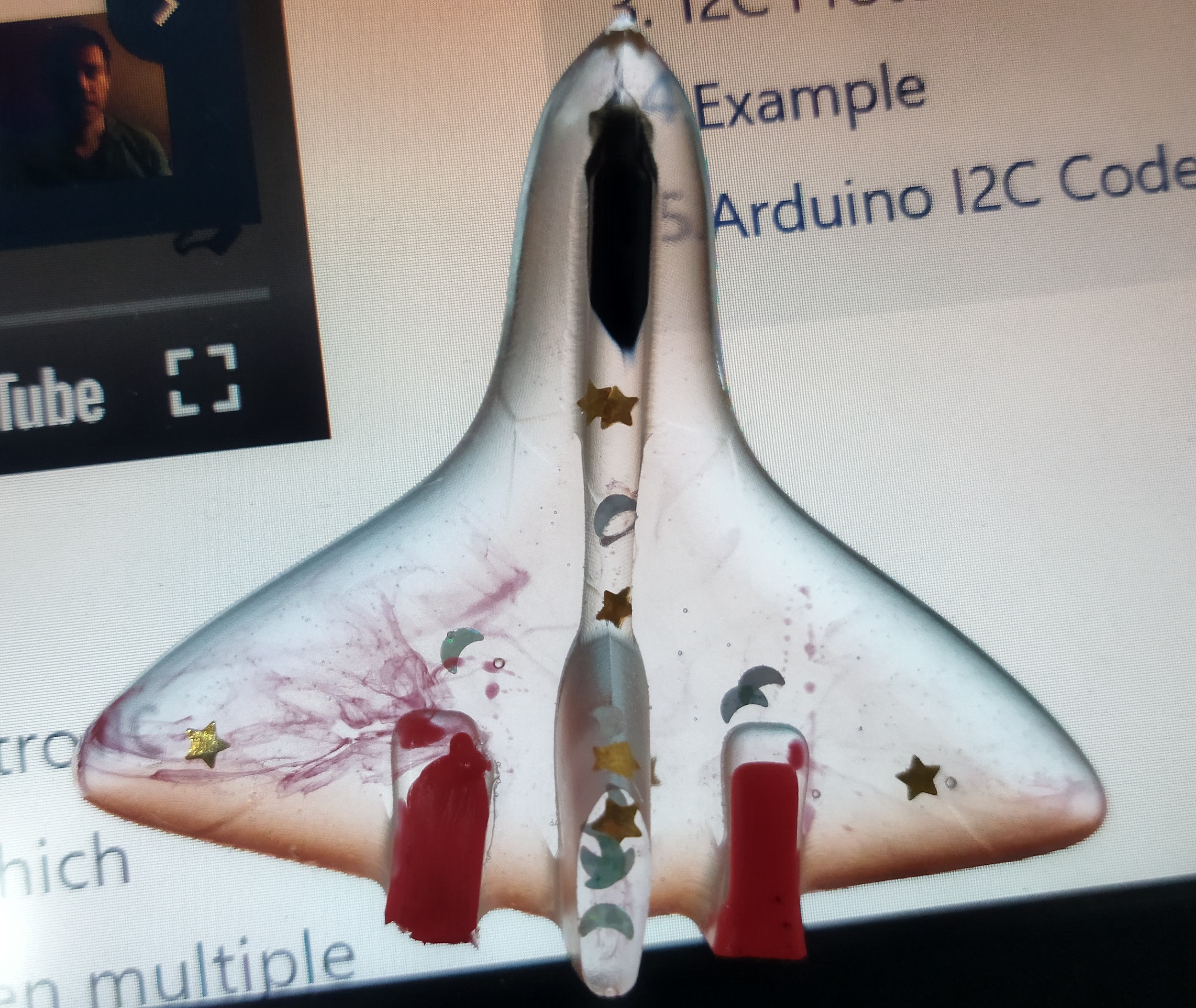
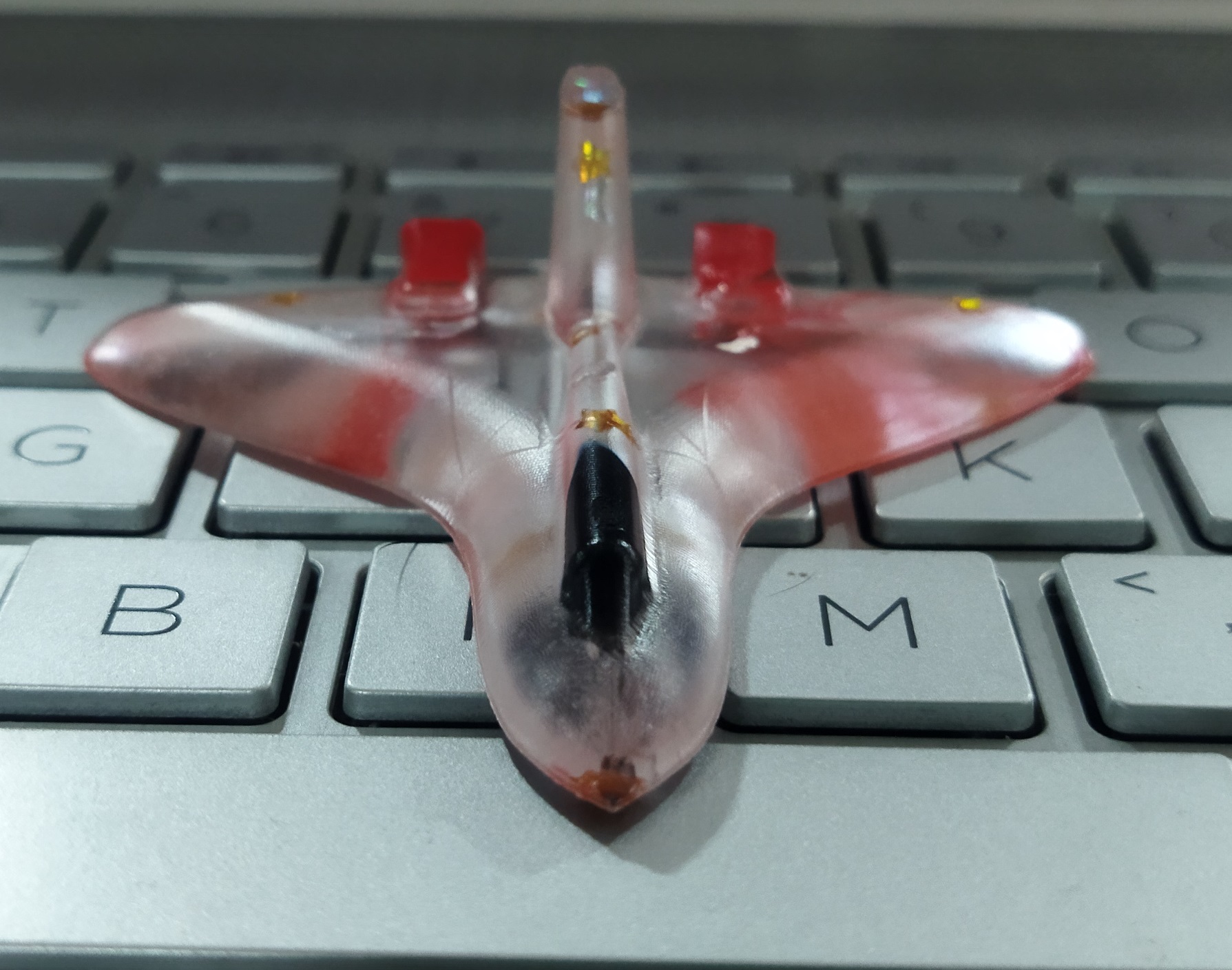
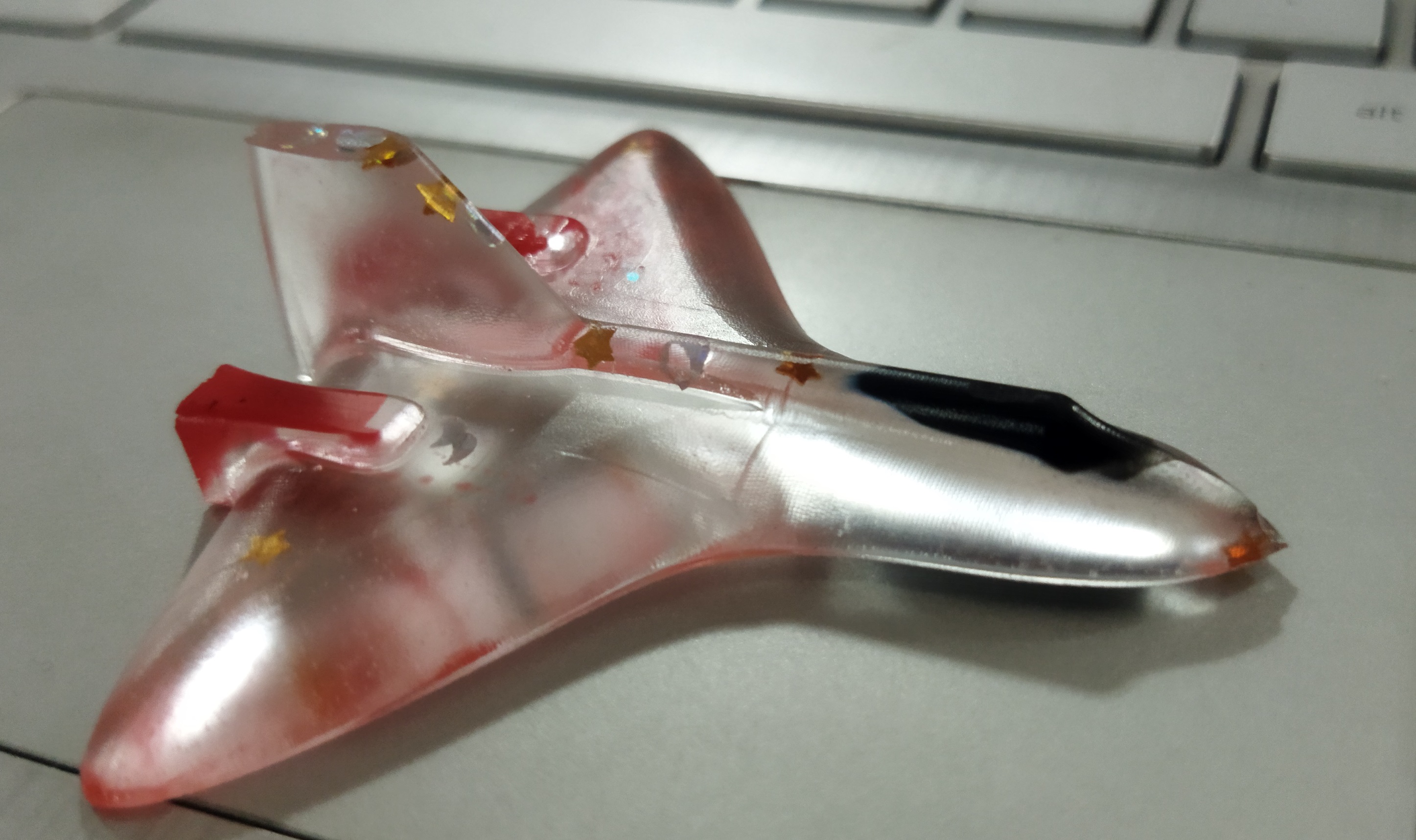
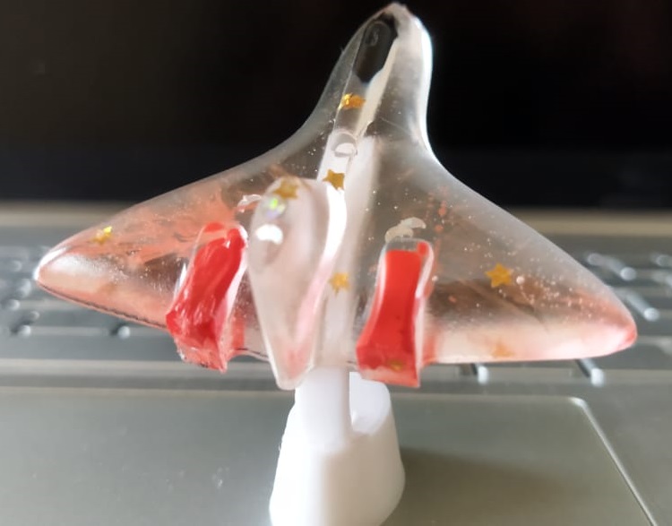
The colour you see is added extra. Initially I mixed some resign with black colour and pour to muold and allow it to solidify. Then I puored the blance with clear resin. some red colour and glits are also added at this time.
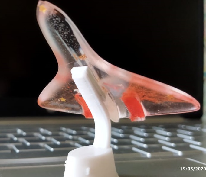
Made a 3D printed stand to hold the plane as shown.
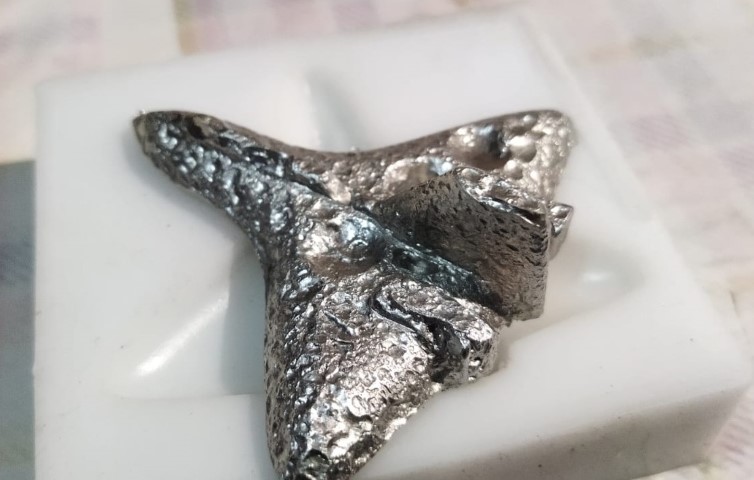
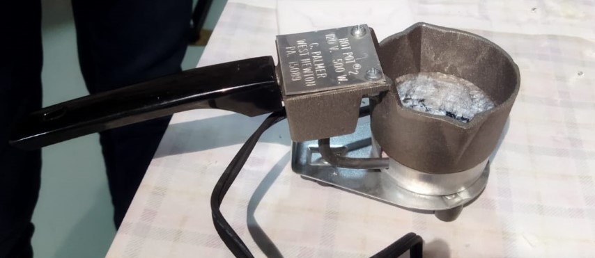
This time I cast it with Bismith(Bismuth is a brittle, silvery-white metal with a pinkish hue.
It has a relatively low melting point of 271.4°C (520.5°F), which is the highest among the non-toxic metals.)
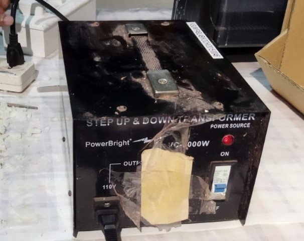
This is the oven uded to mentl the bismith metal.Its operated in 110V.
So a step down transsfprment is used.
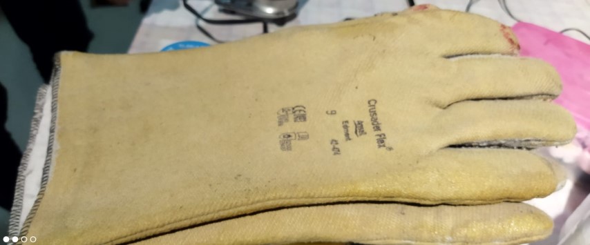
proper safty shall take before handling. Leather gloves and goggles.
My Instructor sayes due to some moisture, tehis type of sufrace is formed and saked me to pre heat the silicon mould with the hot gun.