3. Computer controlled cutting
Objective
Cut something on the vinylcutter design, lasercut, and document a parametric construction kit, accounting for the lasercutter kerf, which can be assembled in multiple ways
Group Assignment page.
characterize your lasercutter’s focus, power, speed, rate, kerf, joint clearance and types
Vinyl Cutter
A vinyl cutter is an entry level machine for cutting vector files with patterns and letters which are directly cut on the roll or piece of vinyl which is mounted and fed into the vinyl cutter through USB or serial cable. Vinyl cutters are mainly used to make signs, banners and advertisements.
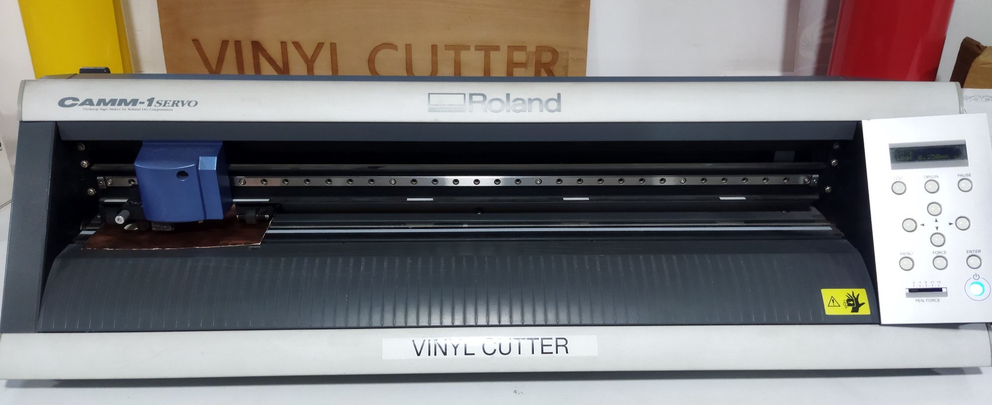
Roland CAMM-1 Servo
We have Roland CAMM-1 vinyl cutter machine i our lab.This is a simple machine like a printer. The knife can rotate on its axis and the Cutting Carriage moves to the left and right and the blade attached to it cuts the vinyl sheet. It has two rollers for moving the sheet back and forth. The sheet is cut by moving the knife over it. We can set the cutting velocity and cutting force depending on the material of the sheet we are cutting. For loading the sheet, there is a lever at the back side of machine. After loading the sheet, this lever is raised up for loacking.
Steps for cutting Vinyl
- First I downloaded an image in PNG.
- Transfer the file in CBA modes.
- Calculate and set the force for vinyl cutting .
- Switch ON vinyl cutter machine and load the vinyl roll.
- Set the orgin in vinyl cutter.
- Click the start button.
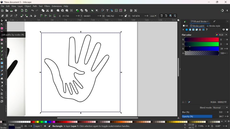
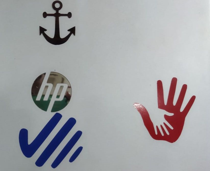
I downloaded the image in Inscape and tace the bitmap and edge detection was made. This file was saved in PNG and file was transfered to computer whic is connected to the viny cutter.
- Vinyl sheet was loaded in machine.
- Position the roller in correct position for adjusting the vinyl.
- Power ON the machine.
- Go to the ‘SELECT SHEET’ option and select ‘ROLL’.
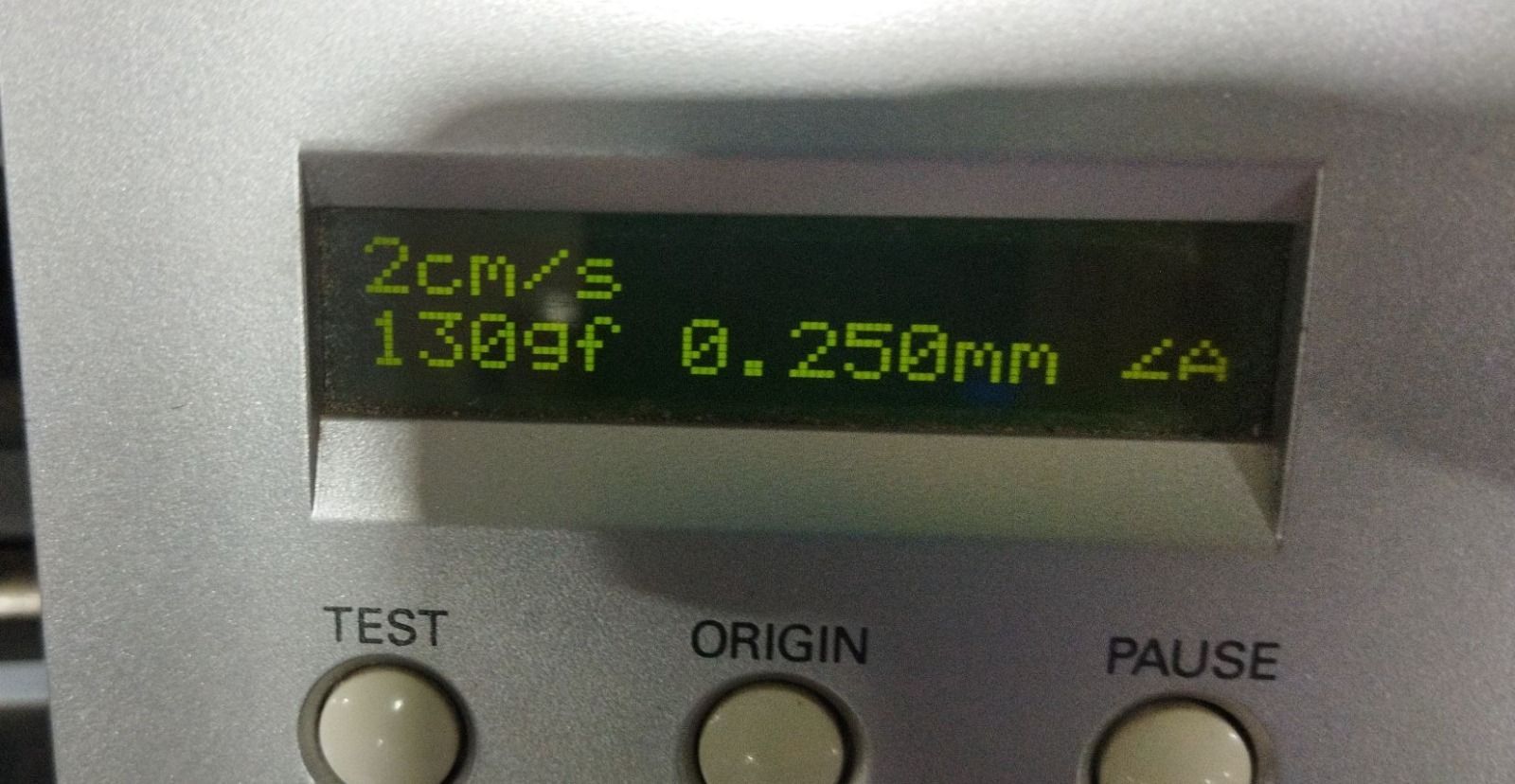
Cutting force and speed set in the machine.
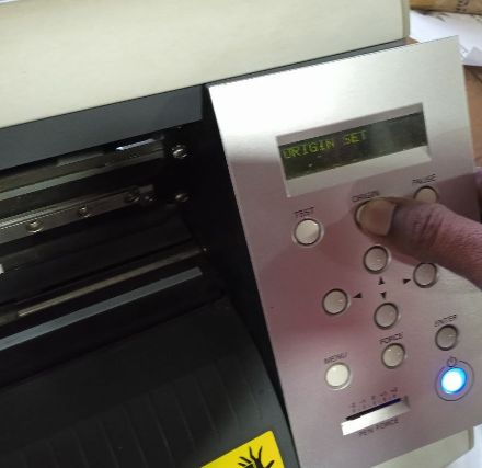
Orgine was set.
Setting up Mods
After receiving the designing file in the computer which connected to vinyl cutter, mods are send the design file into the machine.
Mods is an open-source modular digital manufacturing CAM software developed by MIT’s Center for Bits and Atoms (CBA). Resulting, in a single software controlling any machine from a computer. It can communicate with Laser cutters, vinyl cutters, and CNC mills.
The following steps are used for opening the Mods.
- Open the mods folder and open the terminal in that directory
- Type ‘bash mods-servers’ and press enter. bash mods-servers.
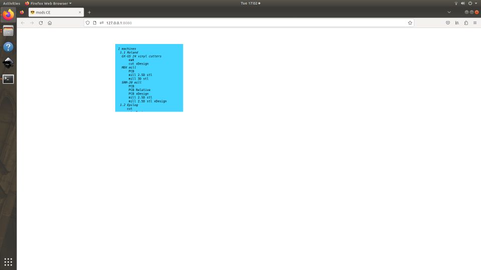
- In the opening window, click the right button of the mouse and select programs.
- Select open program.
- Select Machine→ Roland→CAMM vinyl cutters → cut
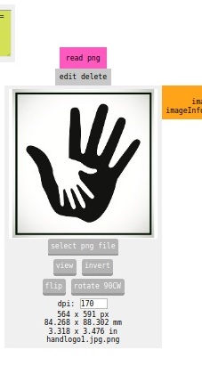
I imported my file by clicking on the ‘read .png’ button
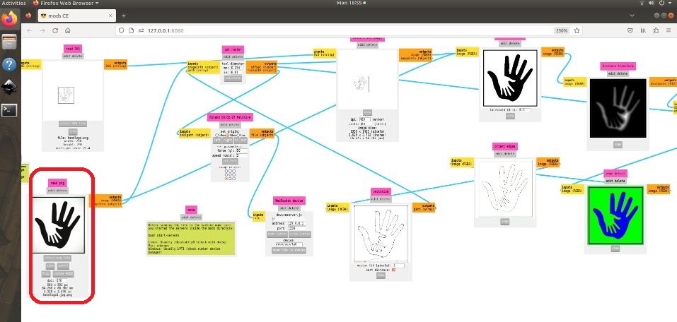
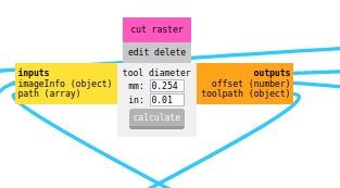
In the ‘Cut raster’ option, I selected tool diameter as 0.254 mm and clicked on Calculate button and cut text was done.
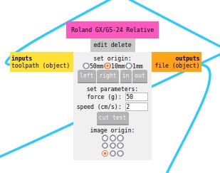
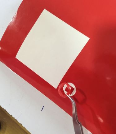
Speed was selected and test cut was made.
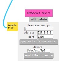
In the ‘Websocket device’ option, I clicked on ‘open socket’ and click on the ‘Send file to device’ option.
Laser Cutting Machine
A laser cutting machine is a device that uses a laser beam to cut materials such as metal, wood, plastic, fabric, and other materials. The laser beam is a highly concentrated and intense beam of light that is directed at the material to be cut, which causes the material to melt or vaporize and leave a clean and precise cut.
There are two different kinds of laser cutting equipment in our fabrication lab. One of them works at the Super Fablab, the other at the FAB Academy.
Trotech Speedy 100
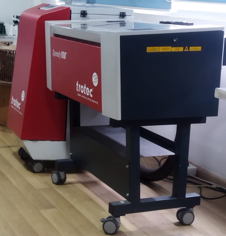
Small enterprises, educational institutions, and hobbyists can use the Trotec Speedy 100, a portable CO2 laser cutting and engraving device. It is an excellent laser system that can cut and engrave a range of materials, include leather, paper, acrylic, wood, and more.
work area = 610 x 305 mm Max work height = 132 mm Laser power CO2 power = 30-60 watts Laser power fiber = 20 - 30 watts
Trotech Speedy 400
A CO2 laser cutting and engraving device made specifically for industrial application is the Trotec Speedy 400. It is a powerful laser system that may be used for a variety of tasks, including the cutting and engraving of materials like paper, plastic, acrylic, fabrics, and wood.
work area = 1016 x 610 mm Max work height = 305 mm Laser power CO2 power = 60-120 watts Laser power fiber = 20 - 50 watts
Regrettably, due to maintenance, both of the laser cutting equipment in our FAB LAB are presently inoperable. We tried using one of the machines to cut a sample, but it seems the laser beam isn’t strong enough to cut through the substance.
Laser cutting machine at Maker village
We were able to use another machine at Maker Village to outsource the project’s laser cutting requirements, but we were unable to finish our individual projects. We took advantage of the chance to finish our group assignment.
Zund G3 L - 2500 
A Swiss company named Zund specialises in creating computerised cutting equipment for a range of sectors.The cutting systems have a reputation for accuracy, adaptability, and efficiency. Paper, cardboard, fabric, leather, wood, and plastic are just a few of the numerous materials that they may cut.To meet certain cutting requirements, the systems can be modified with a variety of modules, including cutting tools, creasing tools, and routing tools.
Zund cutting systems are also known for their user-friendly software, which enables easy and efficient operation. The software includes features such as job management, nesting, and tool path optimization, among others.
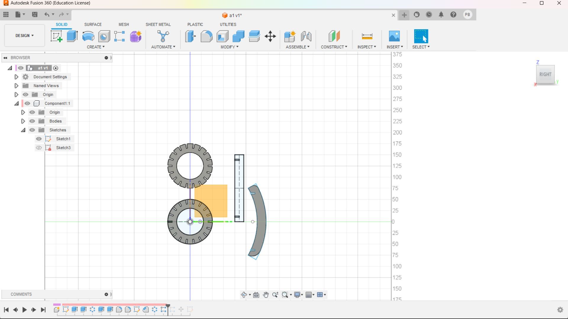
Prametric Design
For the week 3 assignment we have to design a parametric construction kit, accounting for the lasercutter kerf, which can be assembled in multiple ways.
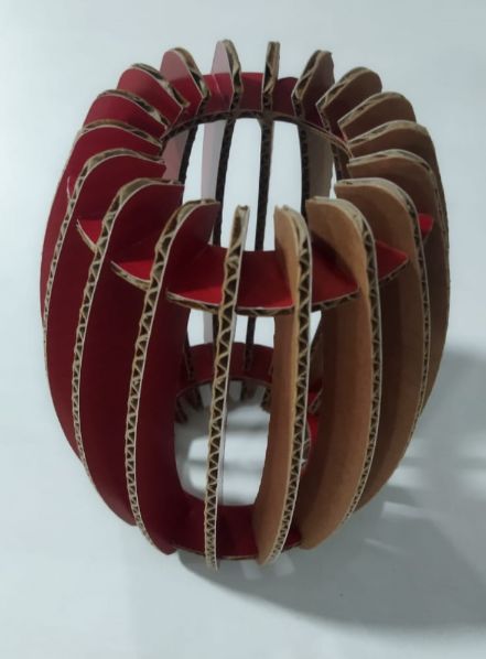
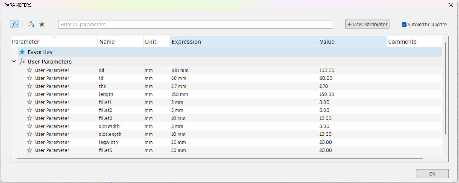
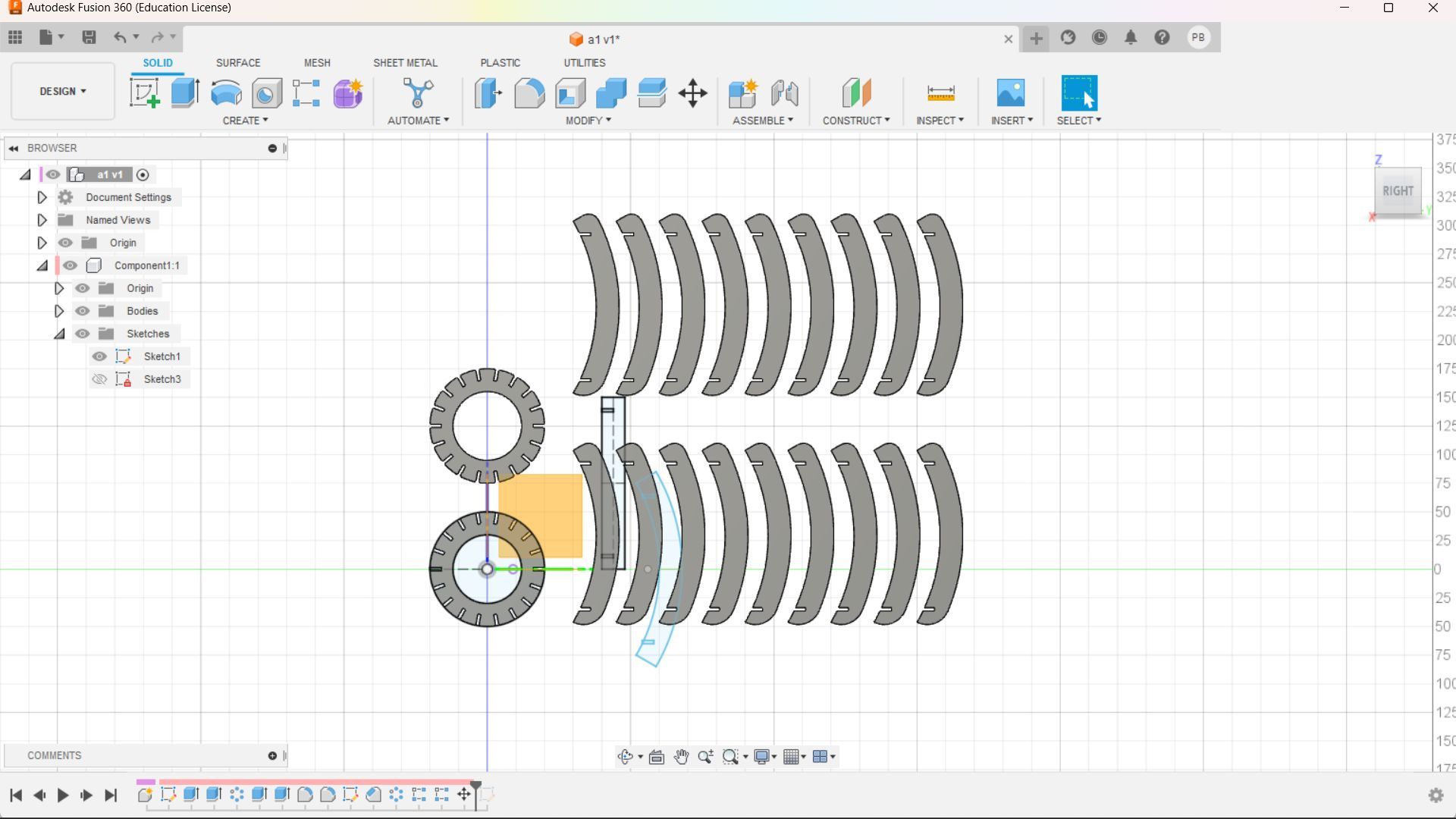
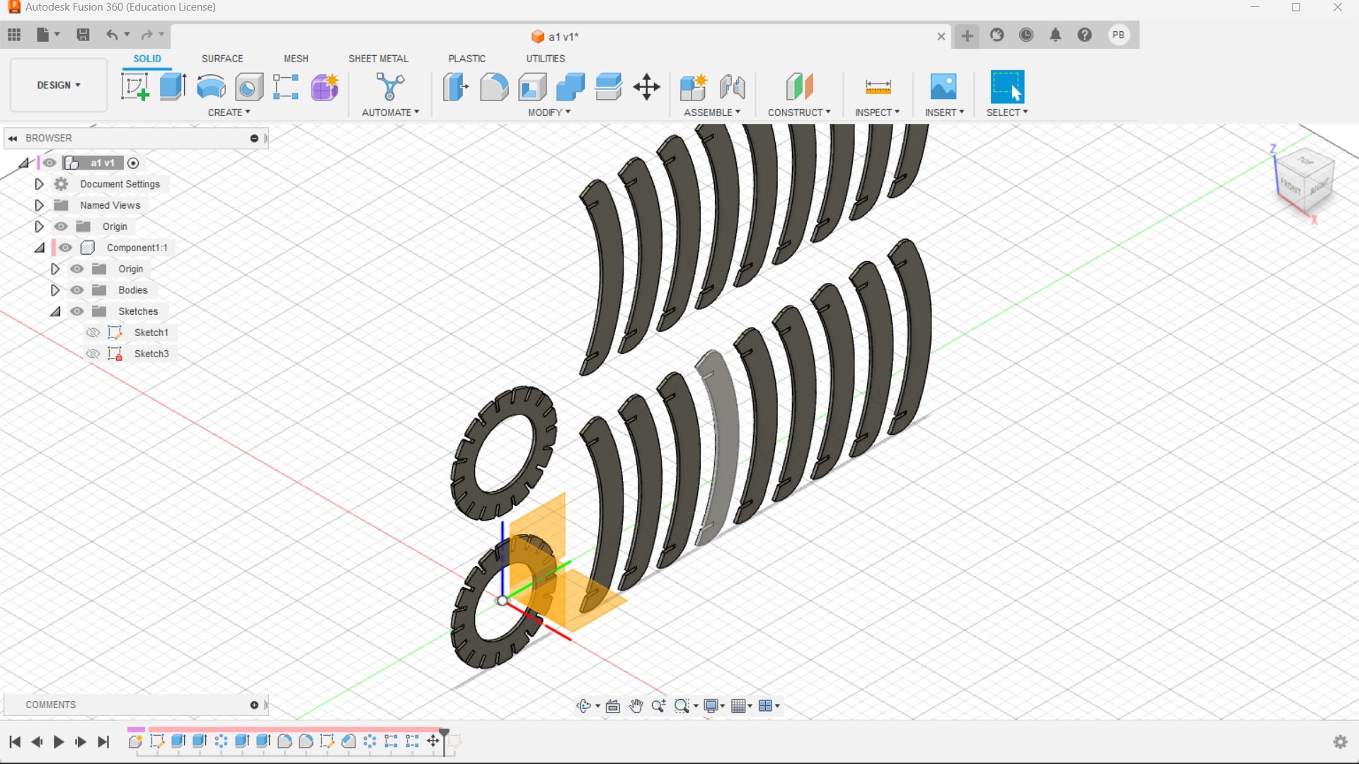
I intended to create a hanging lamp shade here. I utilised Fusion 360’s parametric technique for this. made a single item out of related components and prepared it for duplication. This is not necessary because the Zund programme allows for numerous copies.
Zund Cut editor
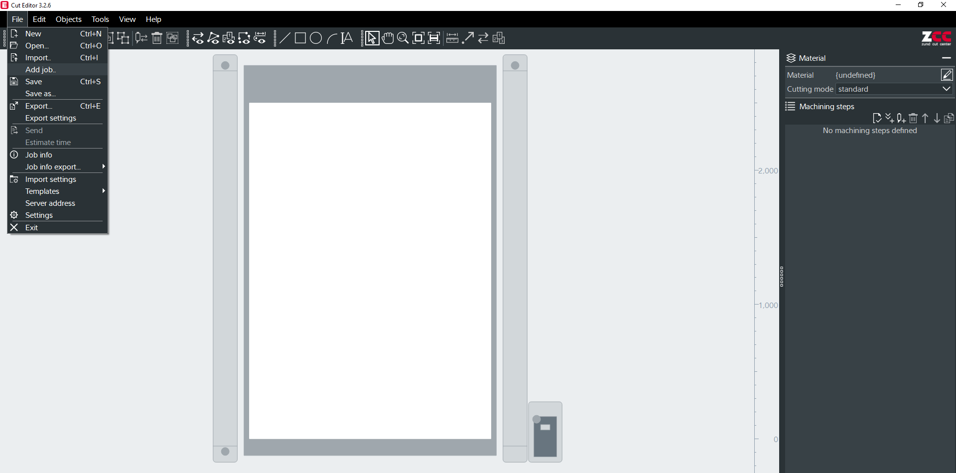
Users can create cutting files, submit them to the Zund machine, and manage the cutting process using the Zund Cut Editor software.
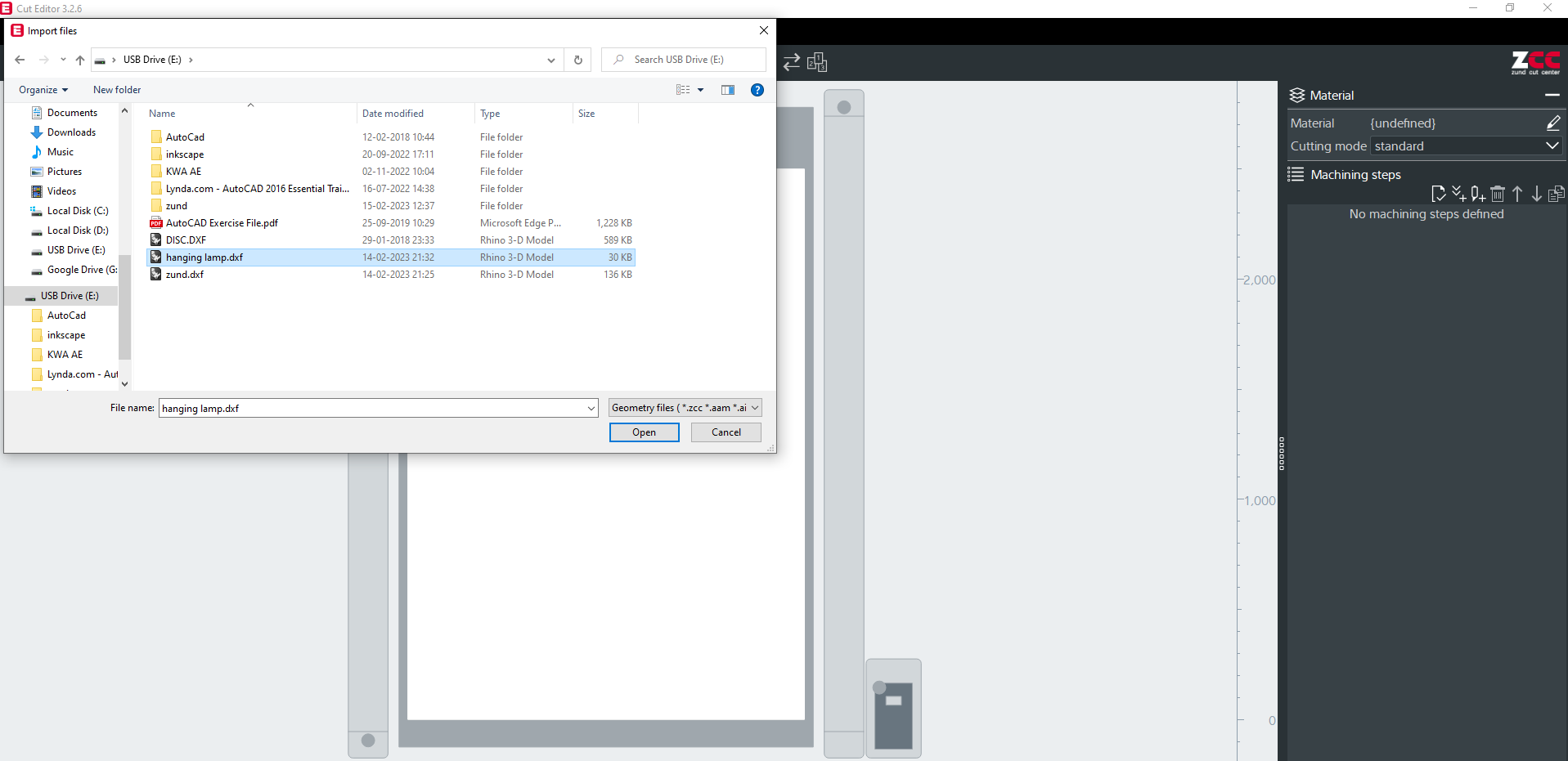
Click on File, then upload Job to upload your dxf file .
Cutting pathways on digital materials can be precisely and accurately created and modified using the Numerical Geometry (NumGeo) tool in Zund Cut Editor. With the help of this tool, users can precisely specify the location, scale, and orientation of cutting lines, curves, and shapes.
You may access NumGeo from the toolbar > objects.
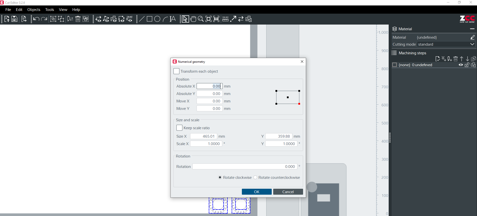
The geometry points were spaced 8 millimetres apart from X and Y.
To move things To move the chosen items, use the arrow keys after selecting them with the mouse and the spacebar.
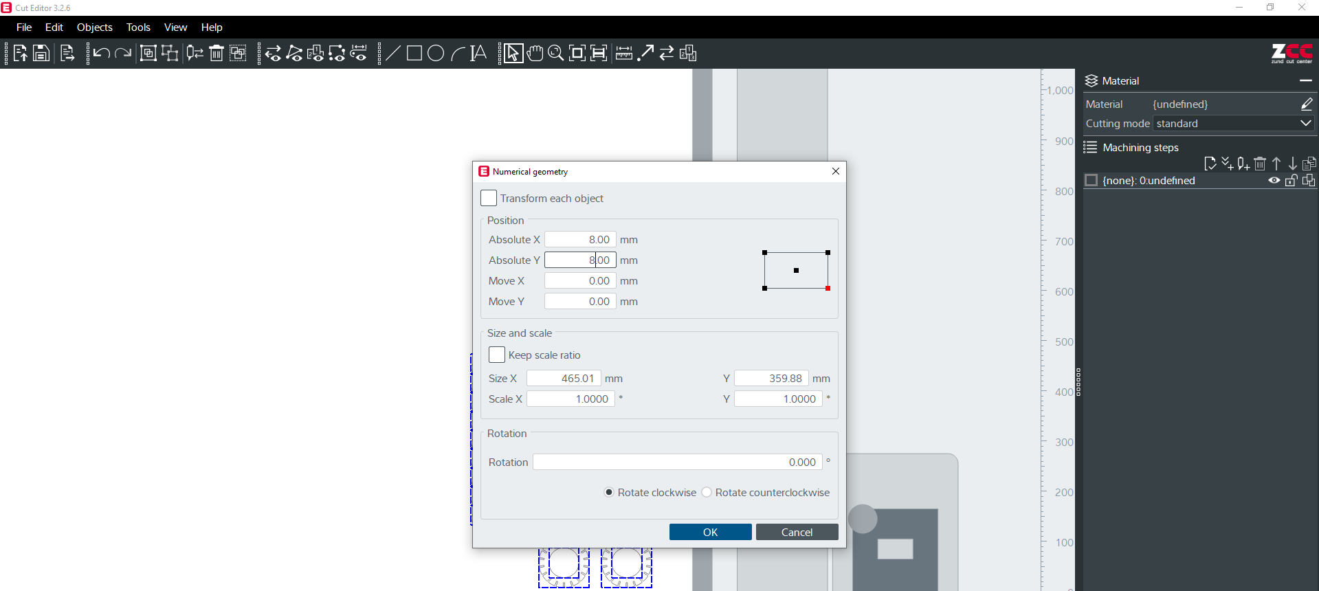
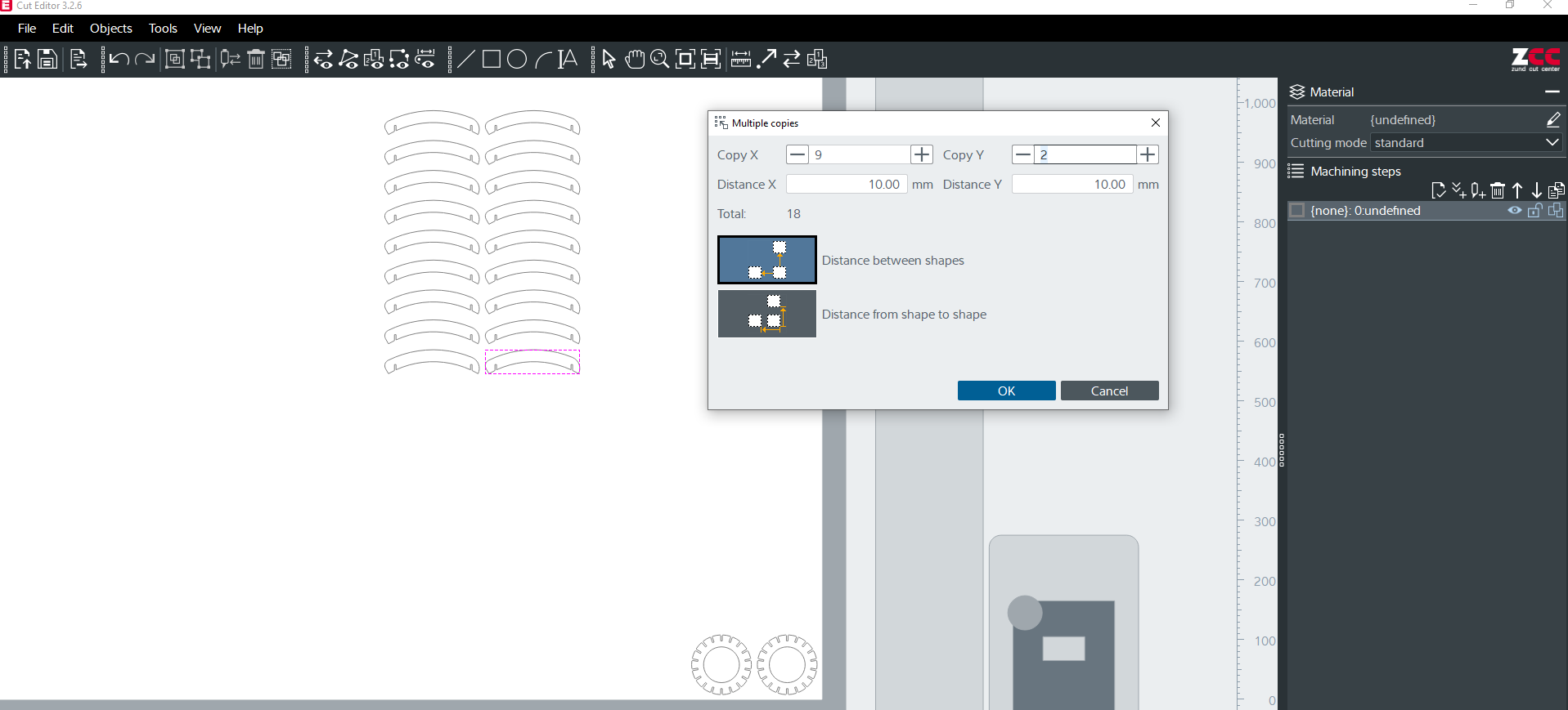
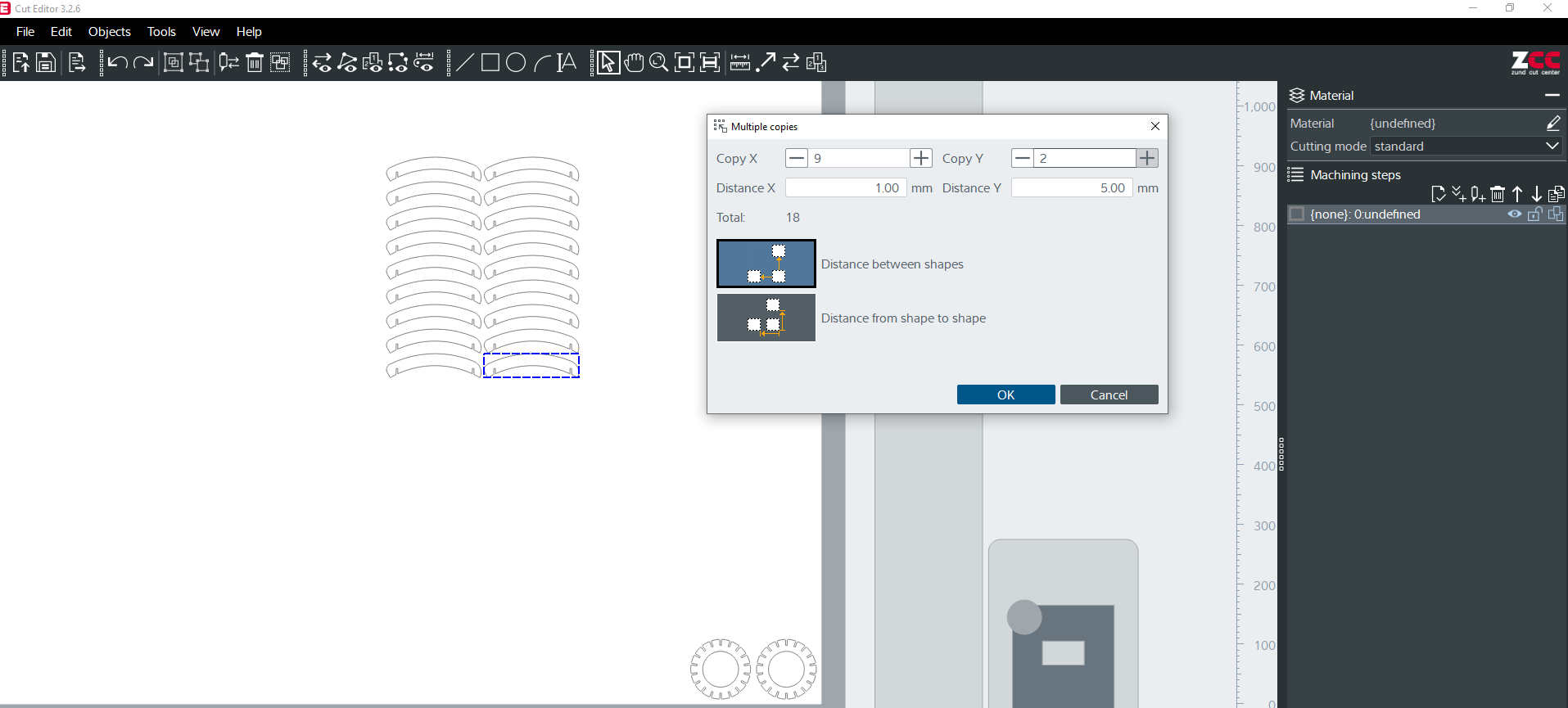
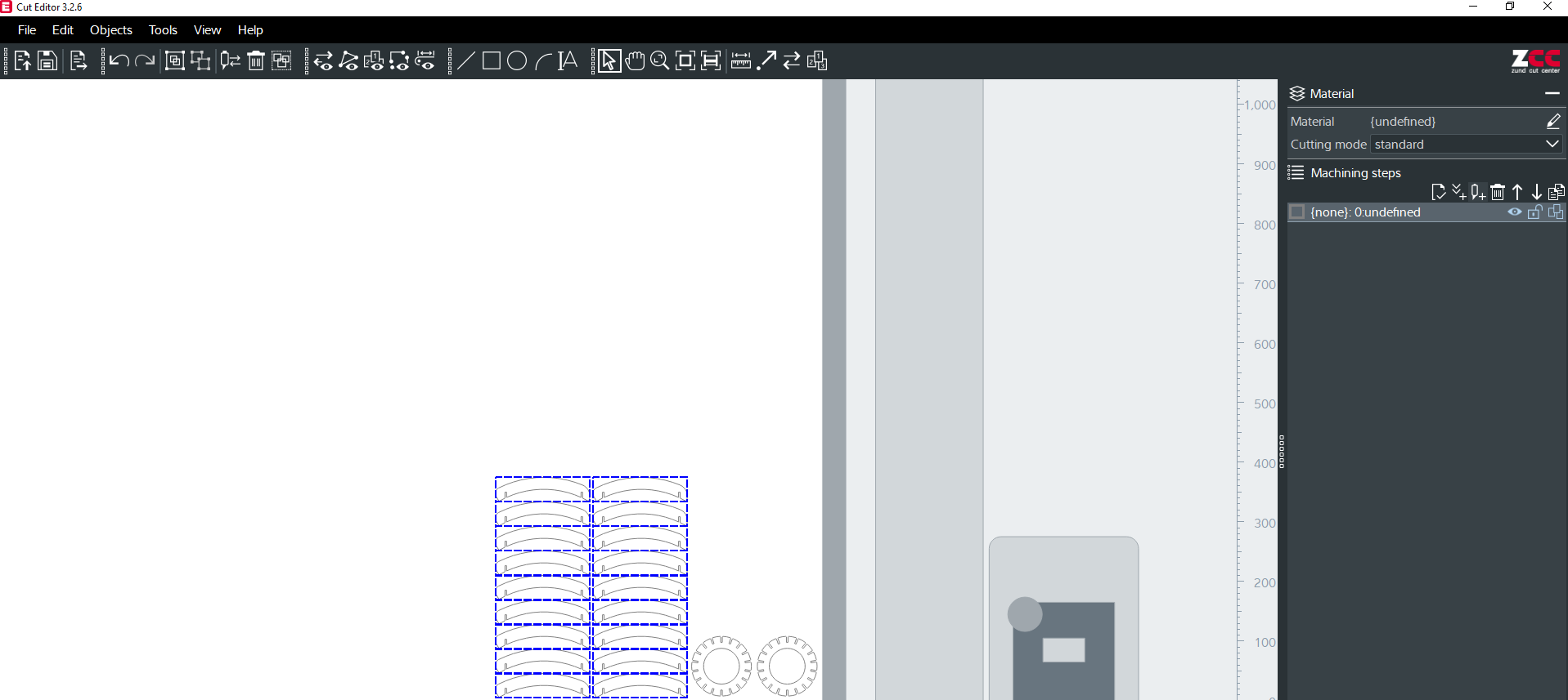
Users of the multiple copy tool can make duplicates of a design and arrange them in different configurations on a single piece of material. The ability to maximise the number of designs that may be cut from a single sheet makes this tool especially helpful for maximising material utilisation and reducing waste.You can change the design’s X and Y direction (distance) settings to widen or narrow the space between succeeding elements.
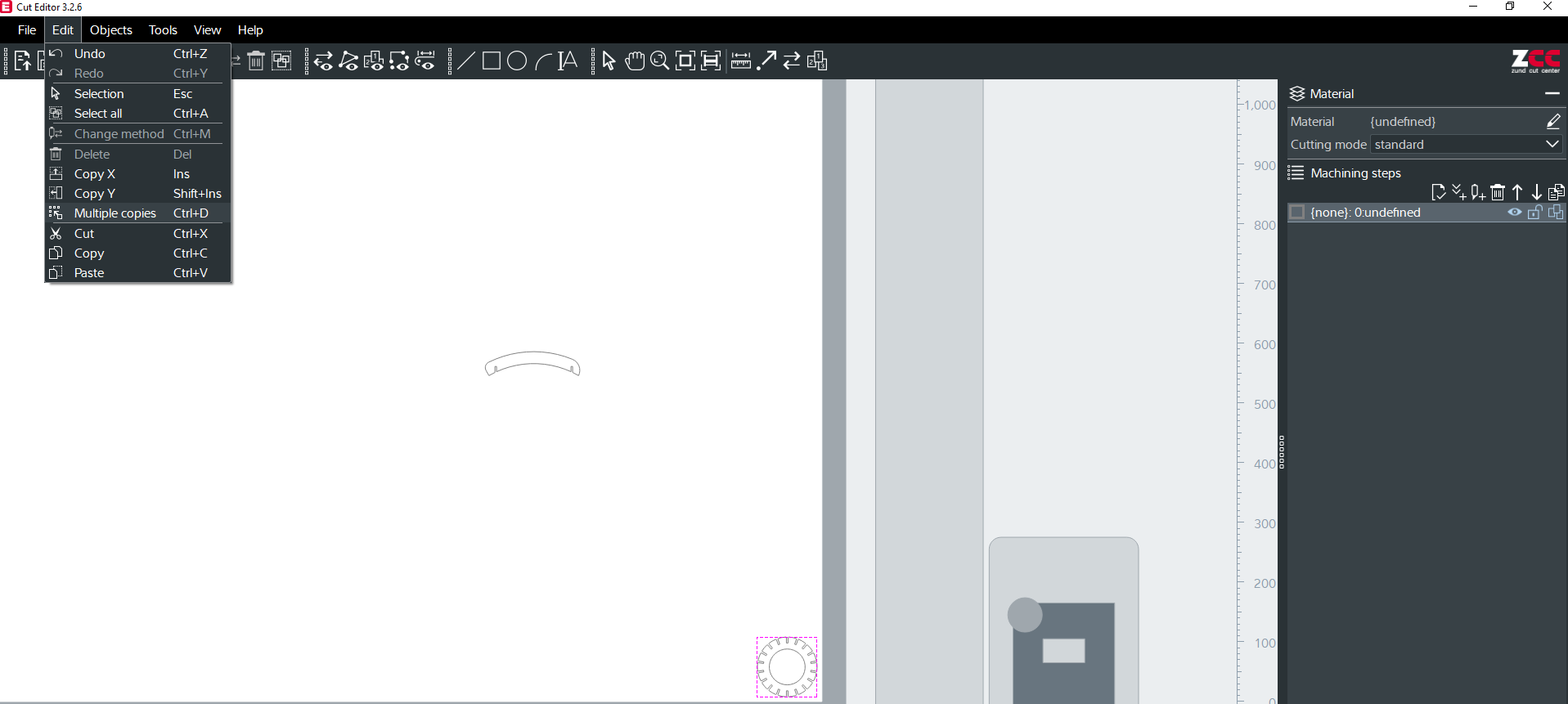
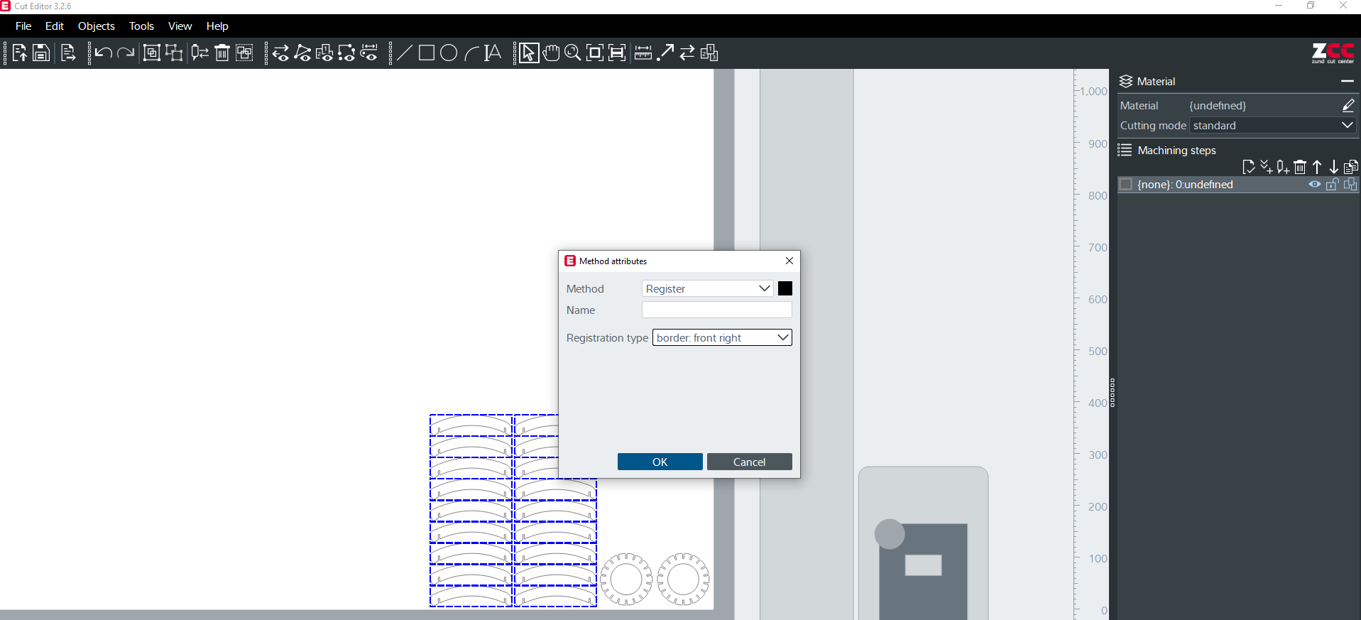
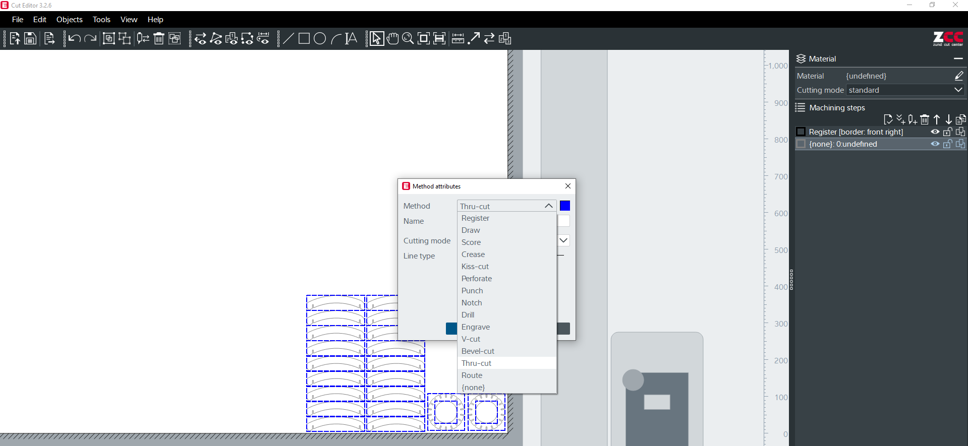
Method attributes
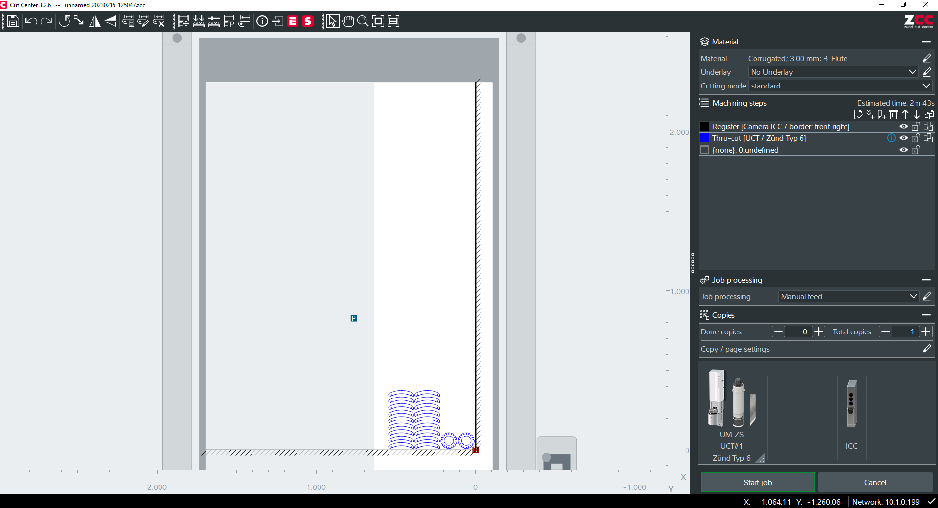
To choose method attributes, pick the symbol for Machining stages that is third from the left. The Thru-cut method (kind of cut) is selected. Through-cuts are cuts that penetrate the entire object, separating it into manageable bits.
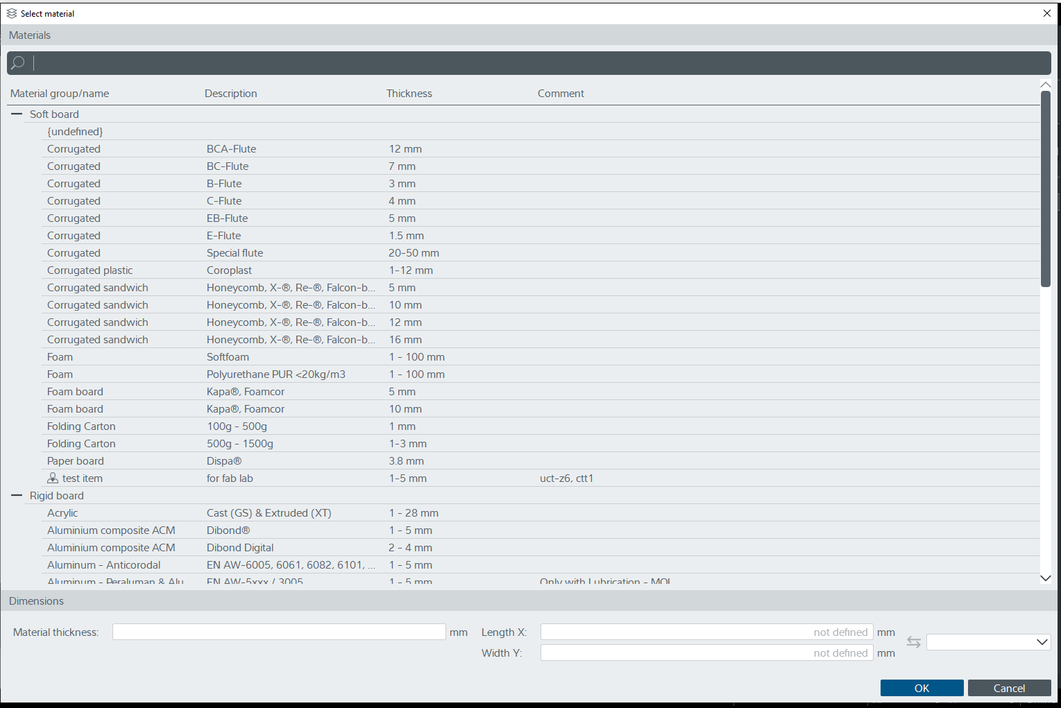
Setting the Material
Select the pen symbol next to materials on the right side to set the material. I intended to cut the materials out of hard paper (3 mm corrugated B-flute). click the OK button to set the item.
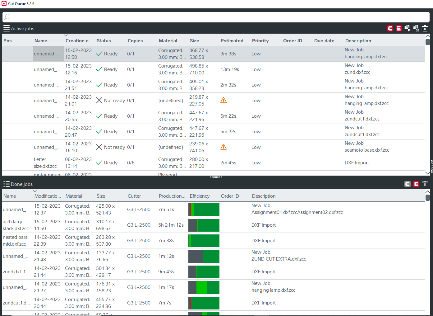
To transmit the files to the editors software, click the send to editor icon. Users can manage and arrange their cutting jobs in a queue using the Zund cut que programme. The Cut Queue gives users the ability to prioritise and control the order in which cutting jobs are executed as well as add, delete, and alter cutting jobs in a list or queue. The status of each task in the queue, along with details on the material, cutting specifications, and anticipated cutting time, is also viewable by users.When you click on the last nameless job, the file name and description appear.
When you double-click a job, the cut queue and cut centre automatically open.Double-click on the tru-cut tab under the machining stages in the Inside Cut centre. To choose the appropriate tool, a popup box appears. EOT is chosen by default; we must alter it to UCT. UCT and EOT stand for the cutting head’s positions for universal cutting tool and electrical oscillating tool, respectively.
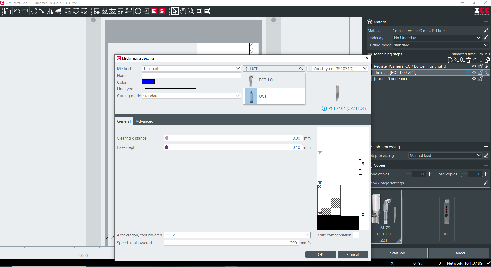
There are options to set speed, feed, and acceleration after choosing UCT.
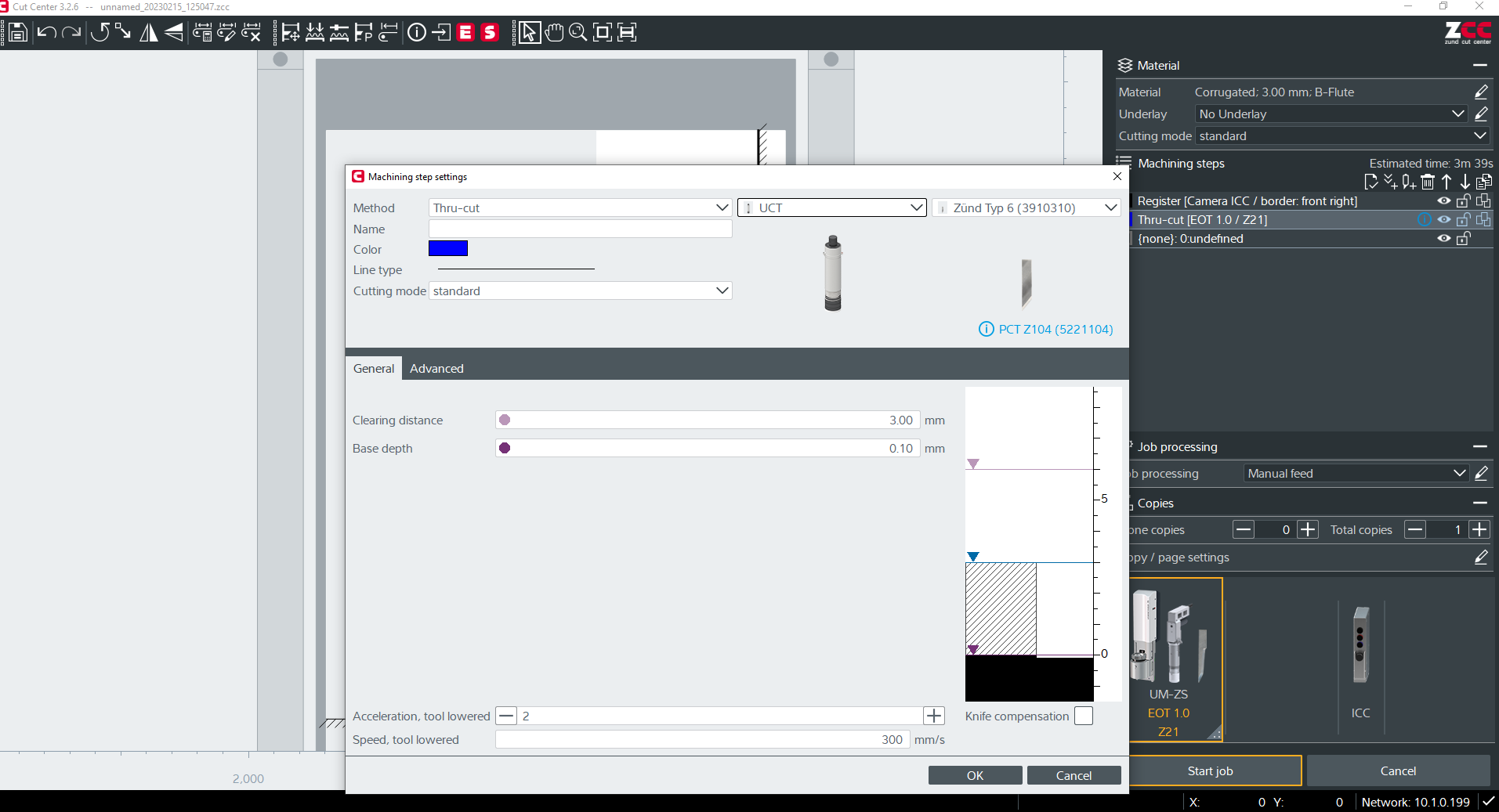
Press the start job button (bottom right) to begin the cutting process.