10. Mechanical design and Machine design
Group Assignment
- design a machine that includes mechanism+actuation+automation+application
- build the mechanical parts and operate it manually
- document the group project and your individual contribution.
We have initiated the brainstorming process for our Week 10 assignment on Mechanical Design and Machine Design. Currently, we are uncertain about the project type we should pursue. However, during this period, we encountered a local issue when a fire broke out at our municipal waste treatment area. Consequently, our attention has shifted towards generating ideas to address waste problems and find effective solutions. It is worth mentioning that this particular idea was proposed by Deepu and myself.
After being unable to find a satisfactory solution for the waste problem and lacking promising ideas for other projects, we made the decision to change our direction. Subsequently, we began exploring a different type of project, and it was during this process that Sibin proposed the idea of creating a SCARA robot. Sibin had expressed his desire to build a robot and discussed it with our fab lab trainer, Shaeen Palayi. During their conversation, SCARA was mentioned as a potential option, and we ultimately settled on it as our project idea.
Following that, we embarked on a search on YouTube to find detailed information on the topic. Shaeen Palayi recommended exploring the YouTube channel “How to Mechatronics” for valuable insights and guidance.
With that inspiration in mind, we commenced our journey to construct a SCARA robot utilizing the materials available in our fab lab inventory.
sketches
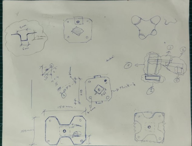
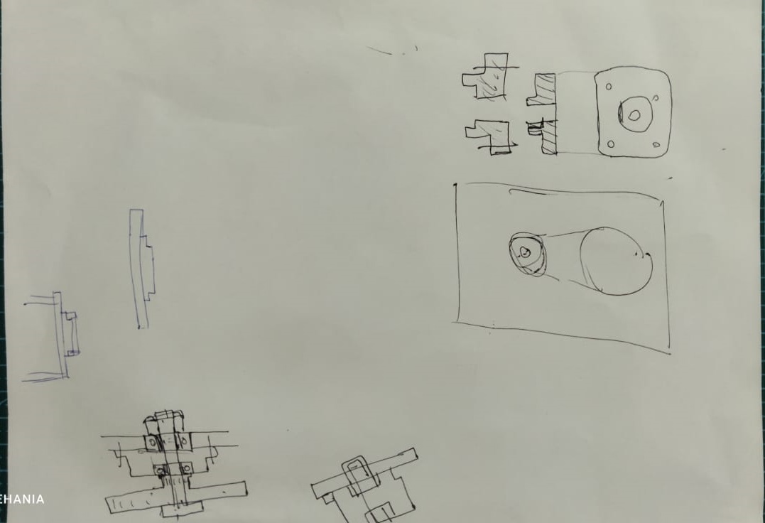
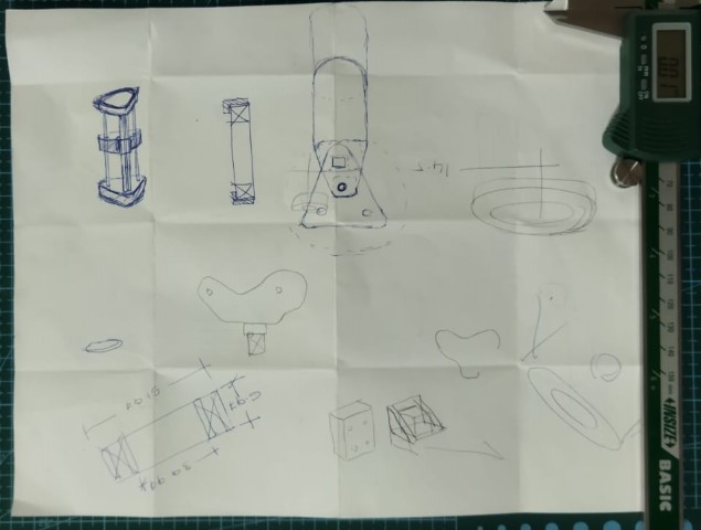
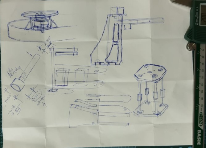
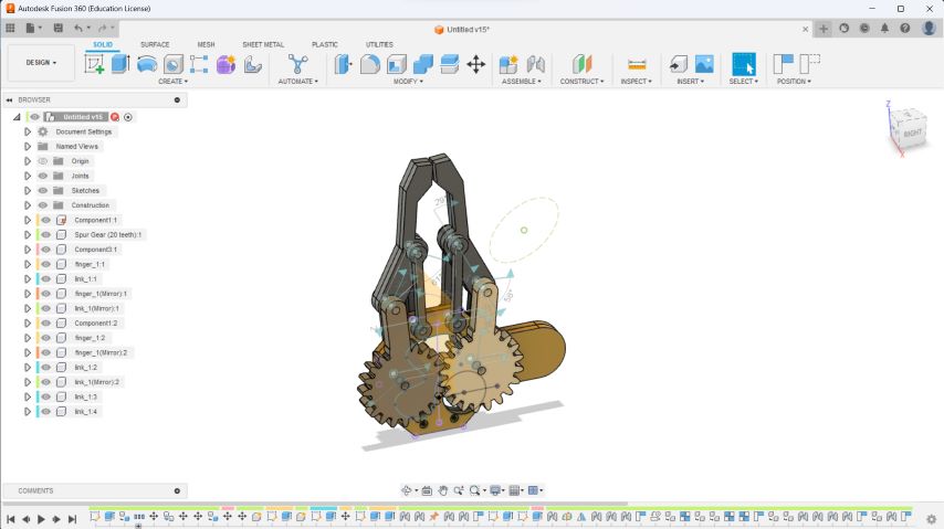
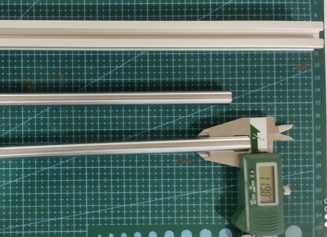
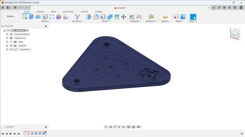
We began by sketching numerous designs of the SCARA robot. Our initial plan involved creating the vertical pillar (Z-axis gantry) using an aluminum extruded profile along with two linear rods measuring 10mm in diameter. This choice was made due to the unavailability of other round rods in our inventory. However, we later acquired four 8mm round rods, prompting us to modify our design. At this point, we transitioned to creating detailed drawings of the SCARA robot using Fusion 360.
On the second day, we utilized the collaborative design feature in Fusion 360, which allowed us to create a shared design workspace. This feature enabled multiple designers or team members to collaborate and work together on a single design project in real-time. Srayes took the lead in setting up this collaborative environment, ensuring that everyone could contribute and make simultaneous modifications to the SCARA robot design.
As a team, we decided to divide the work and assign tasks as follows:
Mechanical Design: Sreyas, Mufeed and myself will take charge of the mechanical design aspects, including the structure, linkages, and joints of the SCARA robot.
Electronics and Control: Deepu will handle the electronics and control system of the robot, such as selecting and integrating the appropriate motors, sensors, and microcontrollers.
Programming and Software: sibin will collaborate on the programming and software development required for the SCARA robot’s functionalities, including motion control, trajectory planning, and user interface.
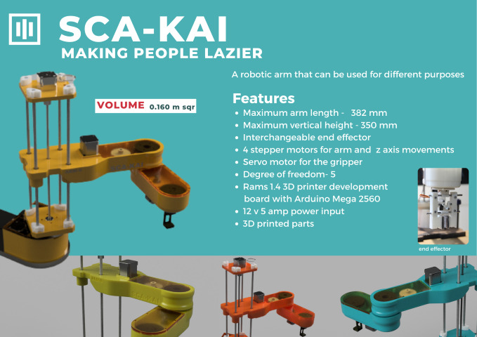
S.C.A.R.A
Selective Compliance Articulated Robot Arm is known as SCARA. It belongs to a class of industrial robots that are frequently utilised in production and assembly operations. When great speed and accuracy are necessary for jobs like pick-and-place operations, assembly, and material handling, SCARA robots are frequently used.
Sreyas took the initiative to start working on the base of the SCARA robot, while myself began by designing the clamp responsible for securing the 8mm round rod linear rod. Once I completed the clamp design, I proceeded to download bearing models from Master Carr within the Fusion 360 software. To ensure compatibility, I cross-checked the dimensions and specifications of the downloaded bearings with the parts available in our lab inventory. This careful validation process ensured that the selected bearings would fit appropriately within the SCARA robot’s assembly.
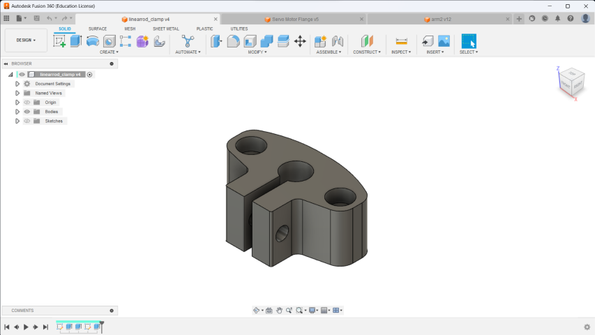
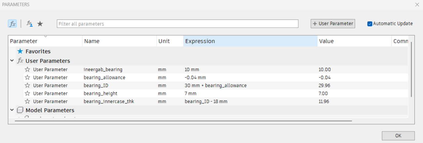
Linear Rod clamp
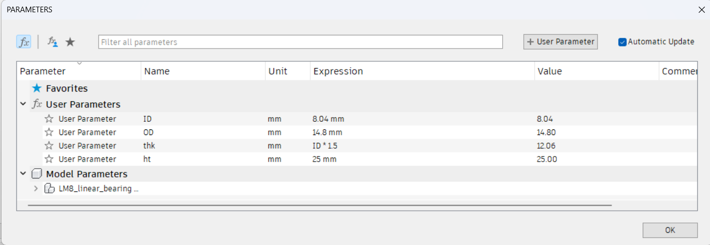
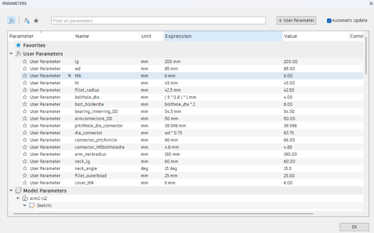
I tried to obtain a linear rod clamp from Thingiverse before, but I ran into problems with the 3D-printed version since it did not work as it should have. Additionally, it was difficult for me to adjust the clamp’s inner diameter (ID) to meet your unique needs. I decided to go with a parametric design strategy as a result. This strategy would enable the creation of a unique clamp with movable parameters, providing the user more control over the dimensions.
 paramentic measurment
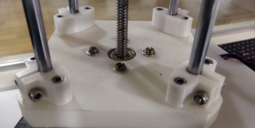
 3D printed and clamped
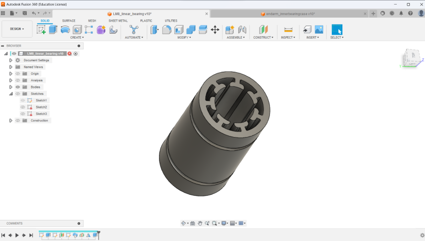
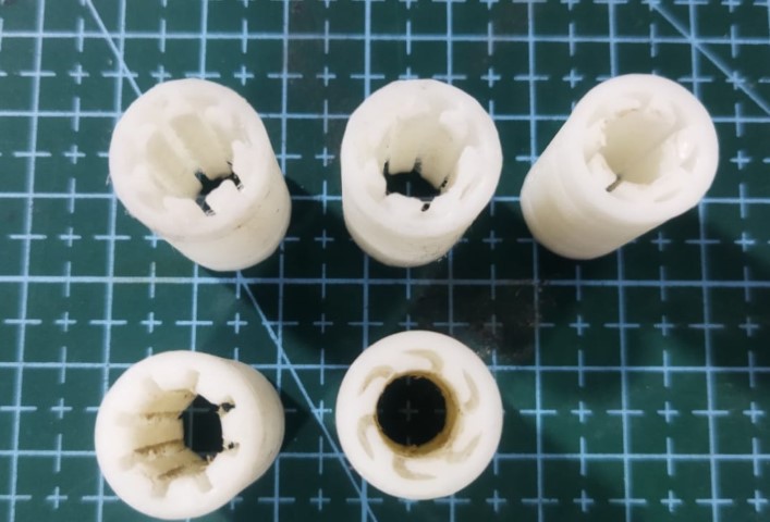
Linear bearing
I finished building the clamp and then moved on to the linear rod bearing. At first, we used a pre-fixed linear rod bearing, but we ran into problems with too much play and subpar construction. We chose to 3D print a replacement bearing because the original was a locally acquired item and not one we had on hand. But even after looking through designs on Thingiverse, we had the same problems with the 3D-printed bearings. As a result, we decided to take matters into our own hands and design the bearing parametrically. The printed bearings did not, however, satisfy the required criteria despite numerous attempts.
We chose to buy a replacement bearing locally to avoid these problems and ensure a higher-quality component. This time, the replacement bearing turned out to be of satisfactory quality, addressing the movement issues and enabling the linear rod mechanism of the SCARA robot to operate more smoothly.
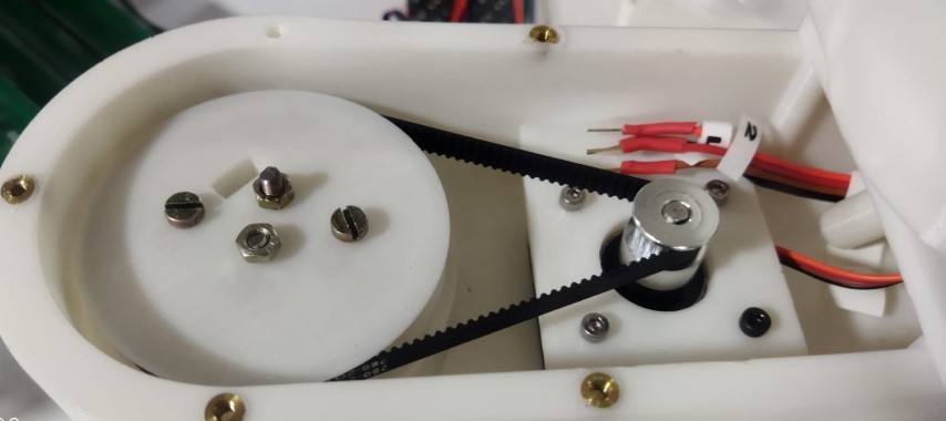
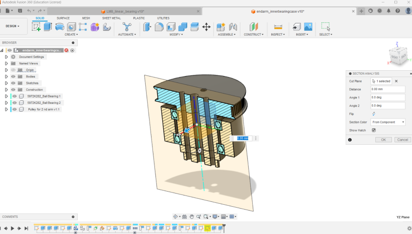
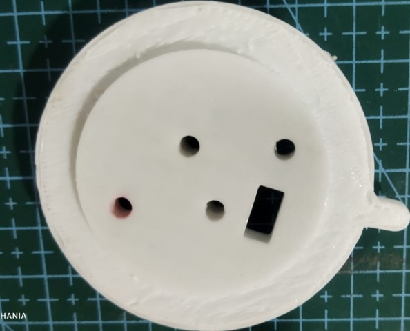
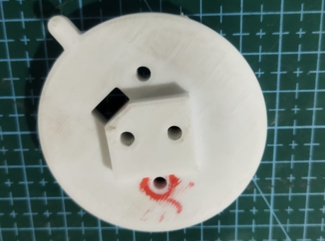
Actuator bearing housing
My next goal was to build the bearing housing that joins the second arm to the end effector after making progress with the linear rod bearing. The second arm’s ability to move is greatly aided by this component. We used two 6806-RS bearings for the end effector’s smooth operation to achieve this. We intended to provide correct support and controlled motion of the SCARA robot’s end effector by incorporating these bearings into the design.
Second Arm
The SCARA robot’s second arm was the next thing we worked on. Throughout this procedure, the structure, connections, and joints that would make up the second arm had to be constructed and designed. I intended to continue the iterative design process to create an efficient arm that would enhance the SCARA robot’s overall performance and capabilities.
Here also I prefered the paramentic design.
Subsequently, I made the decision to step back from designing the second arm of the SCARA robot, as Sreyas had successfully completed the base and took charge of designing arm 2.
End Effector
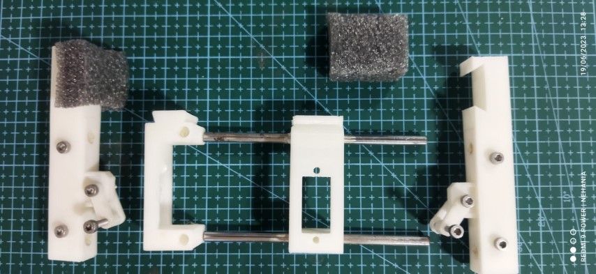
I started working on the end effector design after finishing the bearing housing and second arm. I worked with Deepu to make some adjustments to the end effector holding component after he took the initiative in developing the end effector link and arrangement. Due to the heavy strain placed on it during the trial period, an MG 90 Servo motor was destroyed. This was probably caused by the fact that the holder element was fully 3D printed and lacked the requisite support and padding.I made the decision to alter the holder component by adding a soft sponge material in order to solve this problem. With this improvement, the SCARA robot’s components would be properly supported and cushioned, protecting the servo motor and assuring smooth operation.
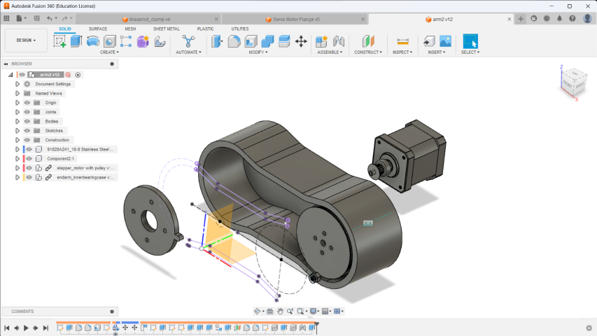
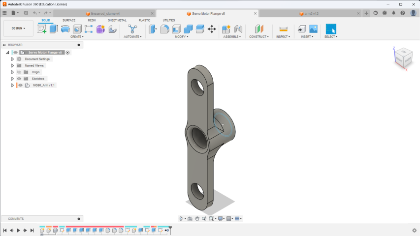
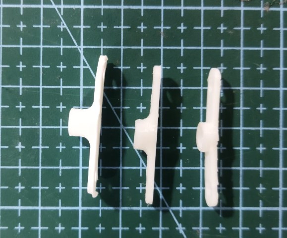
Servo motor Flange
In order to ensure a proper fit between the links designed for the end effector and the servo motor, modifications were made to the servo motor flange. However, difficulties were encountered in obtaining satisfactory results with the internal teeth of the flange, which are responsible for connecting to the servo motor.
To solve this problem, I changed the printer’s parameters, specifically setting the Prusa 3D printer to a finer detail of 0.1mm. The printed parts now perform more successfully and with greater precision thanks to this adjustment’s effectiveness. As a result, the planned end effector links and redesigned servo motor flange fit together perfectly, making it easier for the SCARA robot’s end effector to function correctly.
Subsequently, I made the decision to step back from designing the second arm of the SCARA robot, as Sreyas had successfully completed the base and took charge of designing arm 2.
I created an end geared mechanism later on in the project. The implementation of this concept, however, was not finished in time, and it was not included in the final presentation. Unfortunately, the time restrictions made it impossible to complete this component and incorporate it into the SCARA robot. Despite this setback, the project’s progress and other accomplishments were nonetheless noteworthy and highlighted at the presentation.