4. Embedded programming
Objective
Browse through the data sheet for your microcontroller.
Program a microcontroller development board to intract with local input/output and communicate remotely
Group Assignment
Compare the performance and development workflow for other architectures.
Embedded programming is the process of programming microcontrollers, microprocessors, and other embedded systems to perform a specific function. Embedded systems are used in a wide range of applications, from consumer electronics and home automation to industrial control systems and automotive electronics.
Embedded programming typically involves writing code in a low-level programming language such as C or assembly language, which is then compiled into machine code that can be executed by the embedded system. The programming is done using an Integrated Development Environment (IDE) that includes a code editor, compiler, and debugger.
The code written for embedded systems is typically designed to perform a specific function, such as controlling a motor or monitoring sensor data. The code is often optimized for performance and memory usage, since embedded systems typically have limited processing power and memory compared to traditional desktop or server systems.
Some common tasks in embedded programming include:
Configuring and controlling I/O peripherals, such as sensors, actuators, and communication interfaces (e.g., UART, SPI, I2C) Implementing real-time scheduling and task management Writing low-level device drivers to interact with hardware Optimizing code for size and speed Debugging and troubleshooting issues in real-time systems
Some common tools and technologies used in embedded programming include:
Microcontrollers and microprocessors:
These are the core components of an embedded system, and are responsible for executing the code and controlling the system’s functions.
IDEs:
Integrated Development Environments (IDEs) are software tools that provide a comprehensive environment for developing embedded software. Some popular IDEs for embedded programming include Eclipse, Keil,Visual Studio and MPLAB.These are just a few of the popular IDEs available for developers. The choice of IDE often depends on the programming language, platform, and personal preference of the developer.
Debuggers: Debuggers are tools that help developers find and fix errors in their code. They allow developers to step through code line-by-line and inspect variables and other program state.
Communication protocols: Embedded systems often communicate with other systems or devices using various communication protocols such as UART, SPI, I2C, and Ethernet.
Architecture.
In the simplest terms, architecture in software refers to the overall design and structure of a software system, including its components and how they interact with each other. It’s like the blueprint or plan for a building, but for software. The architecture determines how the system will work, its capabilities, and its limitations. It’s important to design and maintain a good architecture to ensure that the software system is reliable, easy to use, and can perform well.
“architecture” generally refers to the hardware architecture or the internal structure of the microcontroller chip. It encompasses various components and features that determine how the microcontroller operates and interacts with external devices. Here are some key aspects of microcontroller hardware architecture
Arduino IDE
Arduino IDE is an Integrated Development Environment (IDE) specifically designed for programming the Arduino microcontroller platform.
- Download and install the Arduino IDE from the official website: https://www.arduino.cc/en/software.
- Connect your Arduino Mega 2560 board to your computer using a USB cable.
- Open the Arduino IDE and select “Tools” from the menu bar. Select “Board” and then “Arduino Mega or Mega 2560” from the list.
- Select “Tools” again and choose the appropriate “Port” from the list of available ports.
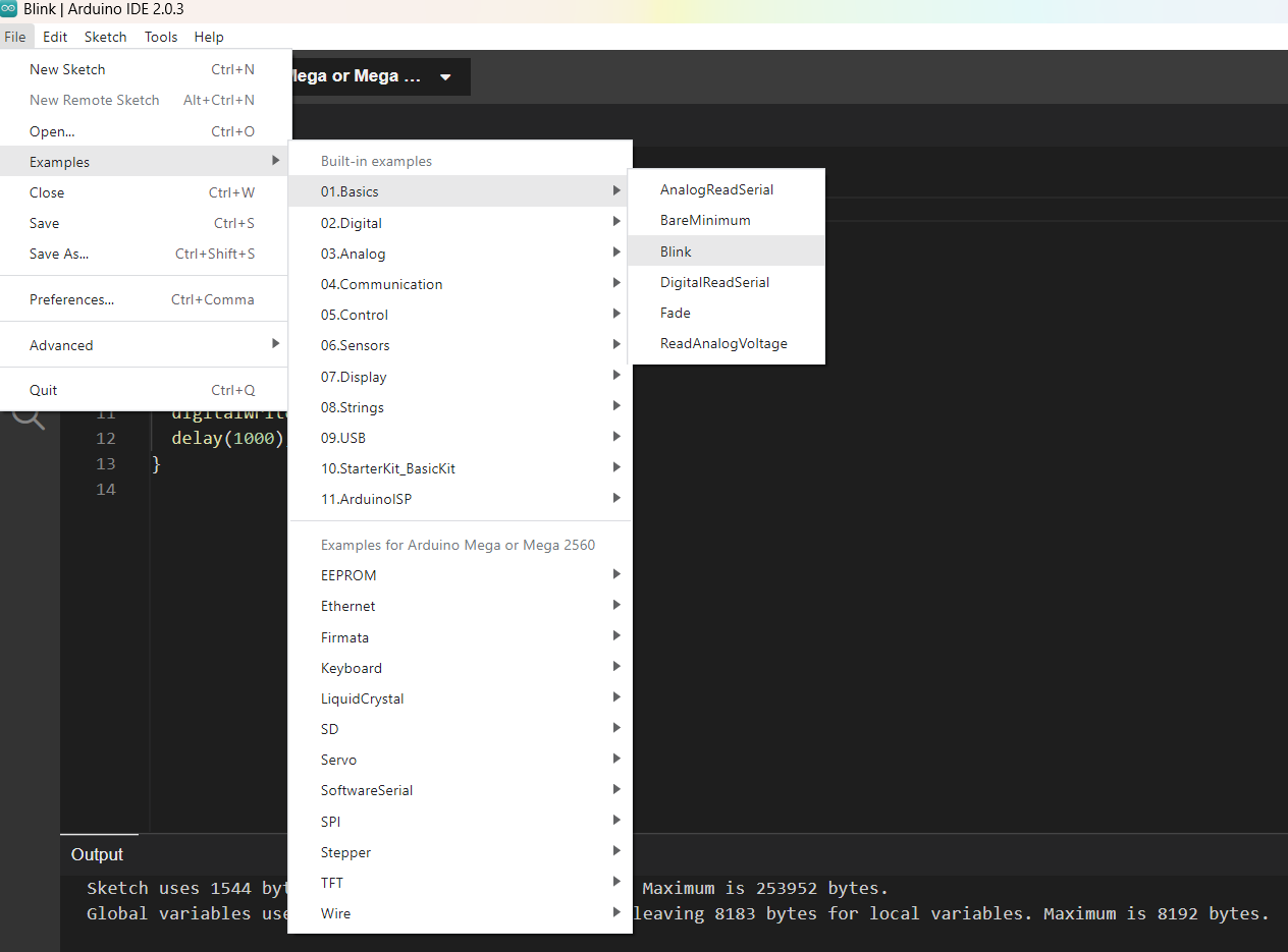
- To create a new sketch, click on “File” in the menu bar, then select “New”. This will open a new sketch window.
- Write your code in the sketch window.
- Once you have finished writing your code, verify it by clicking on the “Verify” button (checkmark icon) in the toolbar. The Arduino IDE will check for errors in your code.
- If there are no errors, you can upload your code to the Arduino Mega 2560 board by clicking on the “Upload” button (arrow icon) in the toolbar. The IDE will compile your code and upload it to the board.
- Once the upload is complete, you should see a message that says “Done uploading”. Your code is now running on the Arduino Mega 2560 board.
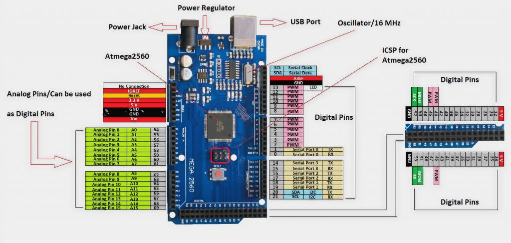
Programming Arduino MEGA 2560
Pinout Diagram
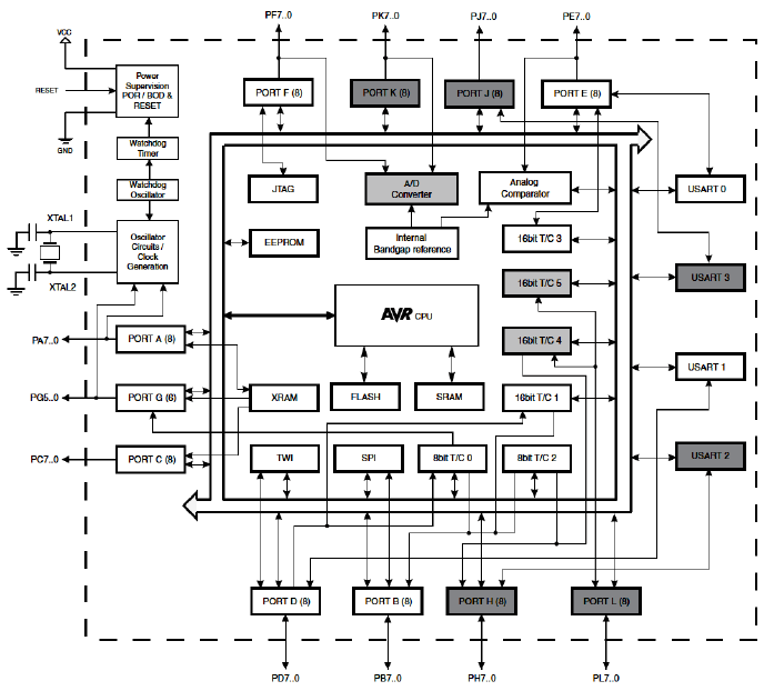
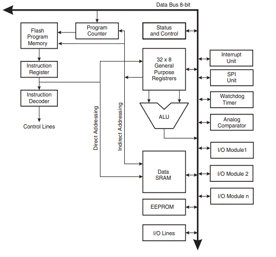
Block Diagream of AVR Architecture
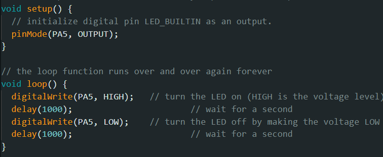
I start with the Blink LED in basic examples avaliable in the library
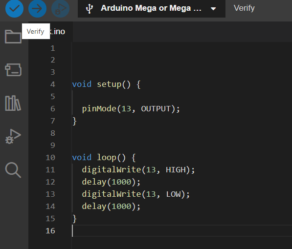
Here I set the pin mode as 13
By refereing the Data sheet the pin numner 13 is set to get the result.
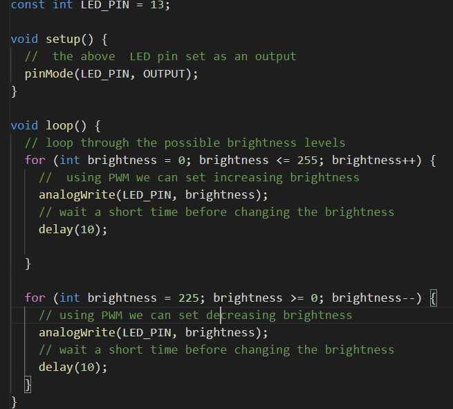
PWM:
PWM stands for Pulse Width Modulation. It is a technique used to control the amount of power delivered to a device, such as an LED, motor, or servo, by varying the duty cycle of a square wave signal.
In PWM, a digital signal is turned on and off at a fixed frequency, and the duty cycle of the signal is varied to control the average voltage and current delivered to the device. The duty cycle is the percentage of time that the signal is high (on) compared to the total period of the signal.
Next I tried with the morsecode.
Programming with ESP Wroom 32 microcontroller
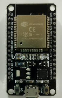
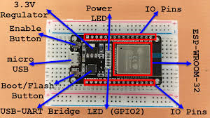
Reading DATA Sheet ESP-Wroom-32
Block Diagram of ESP Wroom 32
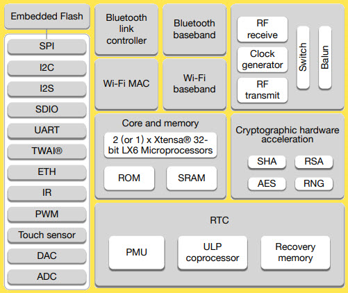
Single or Dual-Core 32-bit LX6 Microprocessor with clock frequency up to 240 MHz. 520 KB of SRAM, 448 KB of ROM and 16 KB of RTC SRAM. Supports 802.11 b/g/n Wi-Fi connectivity with speeds up to 150 Mbps. Support for both Classic Bluetooth v4.
Installing ESP32 Add-on in Arduino IDE
-
First connect the board with the computer with an USB cable.
-
Open Arduino IDE and go to File>Preferences
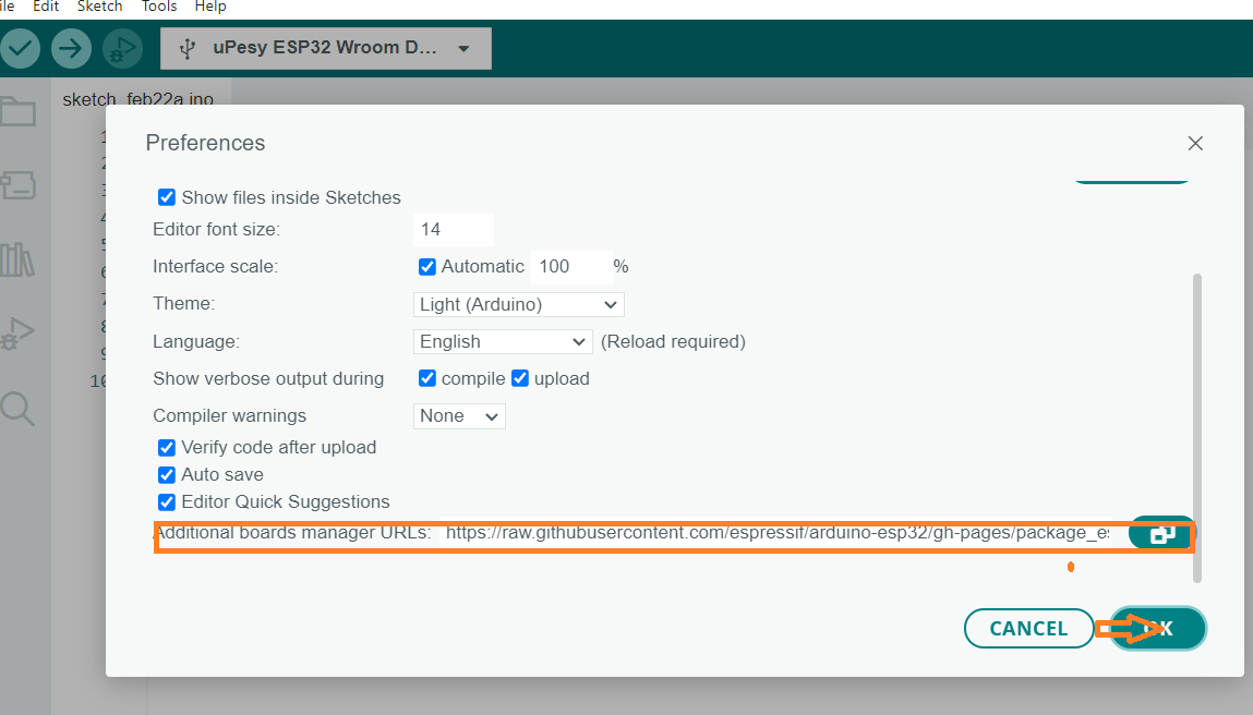
- Enter the following URL here at the additional board manager.
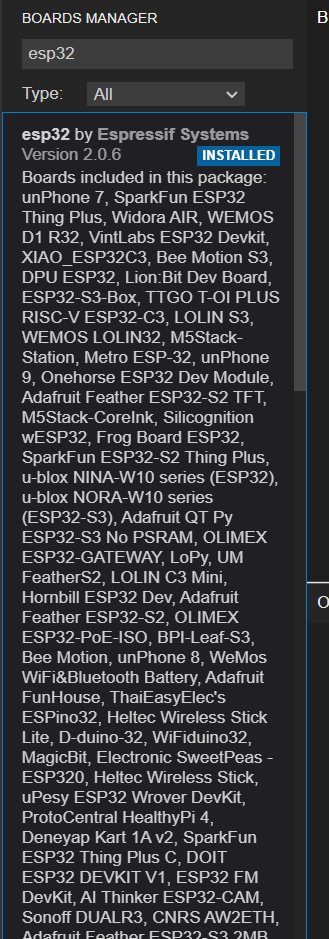
- Then go to Tools > Board > Boards Manager. Search for ESP32 and install the ESP32 by Espressif Systems board definition. Installation is complete.
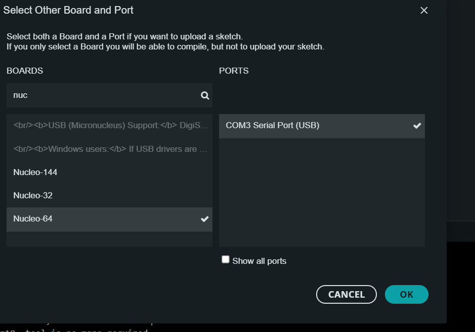
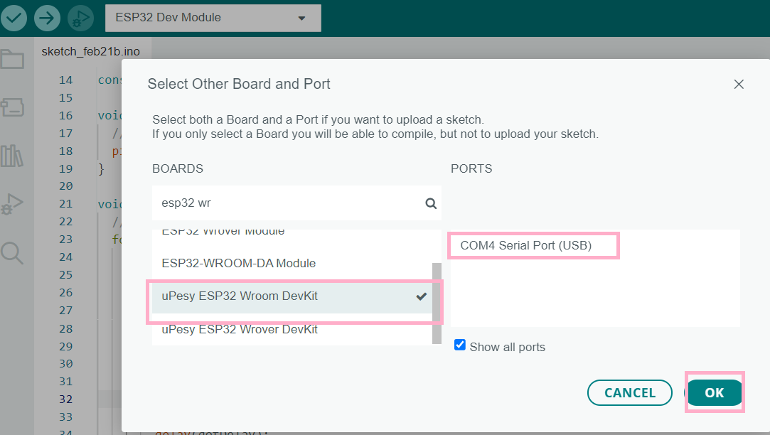 Select ESP32 Dev Module as the board also
select the port. For that go to Tools > Port >
for me it was “COM4”
Select ESP32 Dev Module as the board also
select the port. For that go to Tools > Port >
for me it was “COM4”
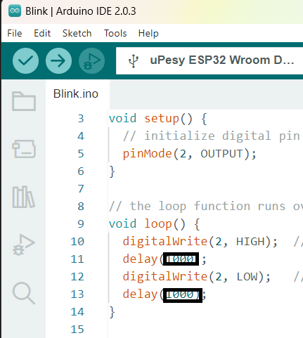
Now the board is connected and i checked the board with the blinking Onnoard LED. For that I used the code avaliable in the library in examples. The delay I put as 500 insted of 1000
Once programming is finished and compiled, it must be uploaded to the board. For that the Upload arrow is pressed, the programme will compile the code again. After that, long press the Boot button on the board will begin uploading the code to the board. Once it is finished the LED lights begin to blink.
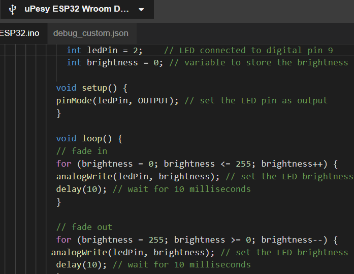
Another example I tried is fade.
Arduino IoT cloud
Arduino IoT Cloud is a cloud-based platform that enables you to develop IoT (Internet of Things) applications and connect your Arduino-based devices to the internet. The platform offers a simple and intuitive interface that makes it easy to set up and manage your IoT projects.
Link for connecting ESP32 with IoT cloud
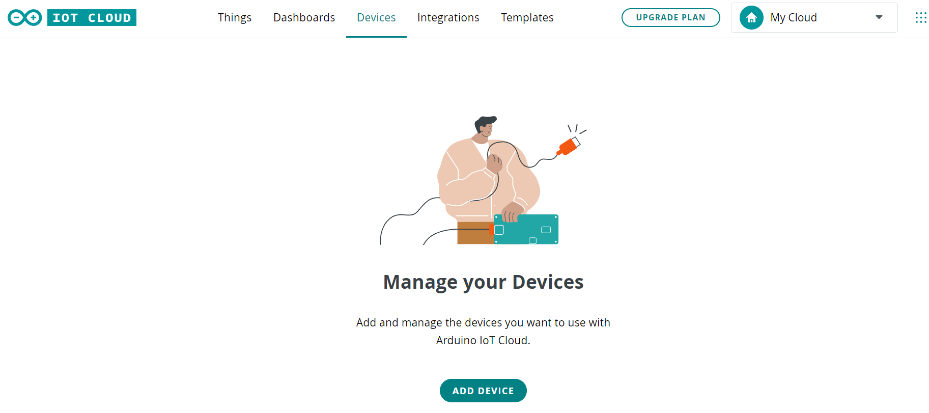
First start with setting up the device
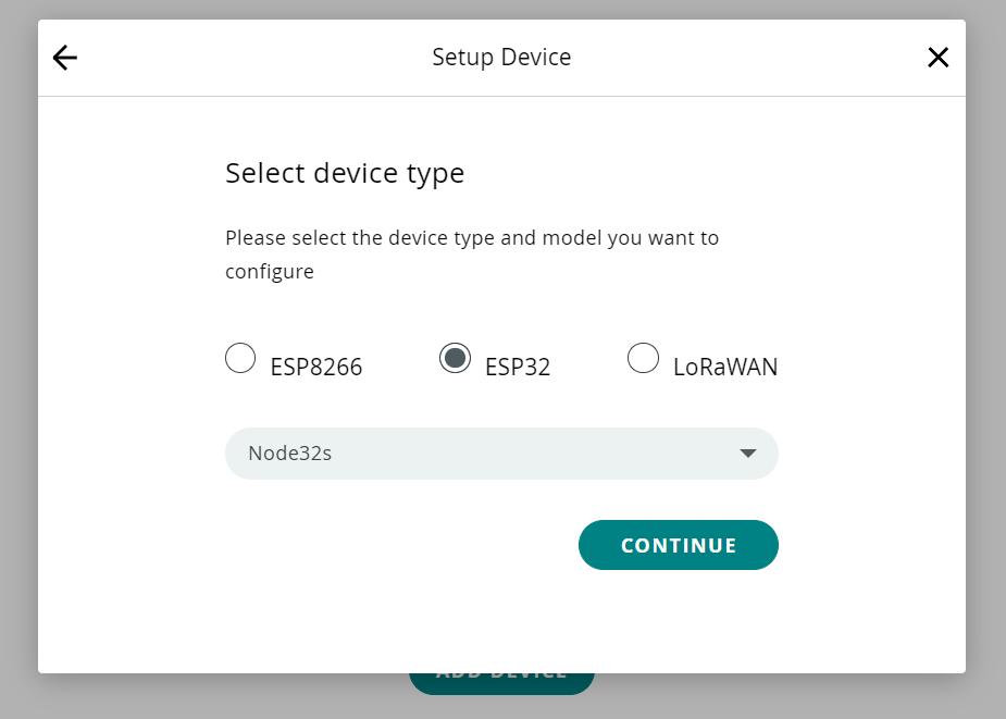
- Go to Cloud IoT by clicking the top right corner.Once in the cloud,click the “Devices” tab.click on “Set up a 3rd party device”.Now we need to select what board we are using. Select either ESP32 or ESP8266, and then choose the board from the drop-down menu.
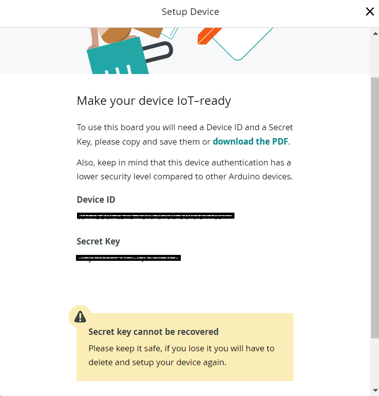
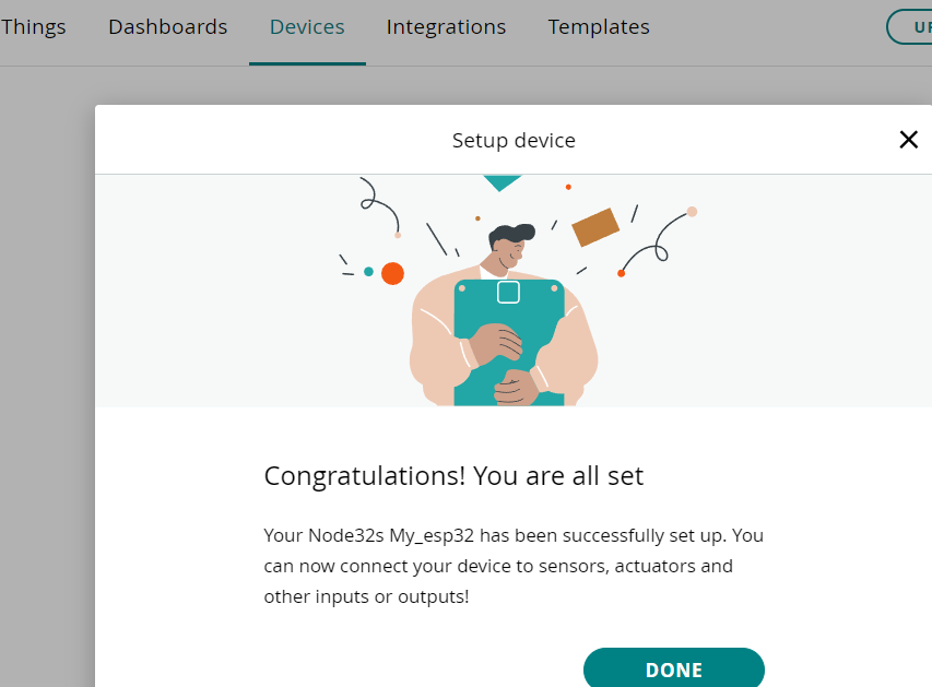
 Now the board needs a name. We choose My_ESP32, ou will now receive your Device ID and Secret key. Please note that the secret key cannot be recovered, so make sure you note it down.When you have saved it, tick the box at the bottom, and click on “Continue”.
Next we have to create a new Thing by clicking on the “Create Thing” button. Now, we need to link our device with our Thing. This is done by clicking on the button in the “Device” section. .Once the device is linked, We need to add the LED switch as a variable to do that go to variables and add the led_switch variable. The data type for this variable is Boolean, the permission is read & write, and update policy is on change. Once done, click on the “Add variable” button.
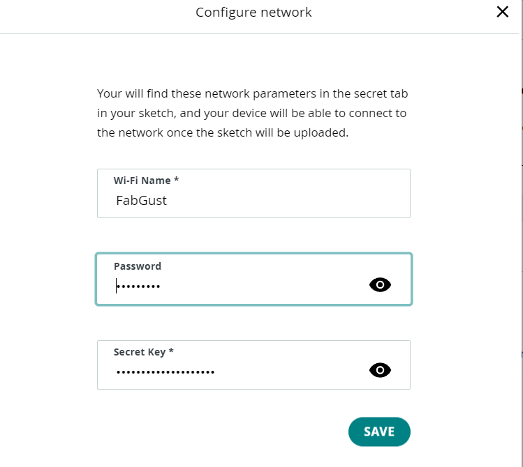
Once done, click on the “Add variable” button.Now, we need to enter the credentials for our network, plus the secret key generated during the device configuration.First, click on the button in the “Network Section”.Then, enter the credentials (network name, network password and secret key). Click “Save” when finished.
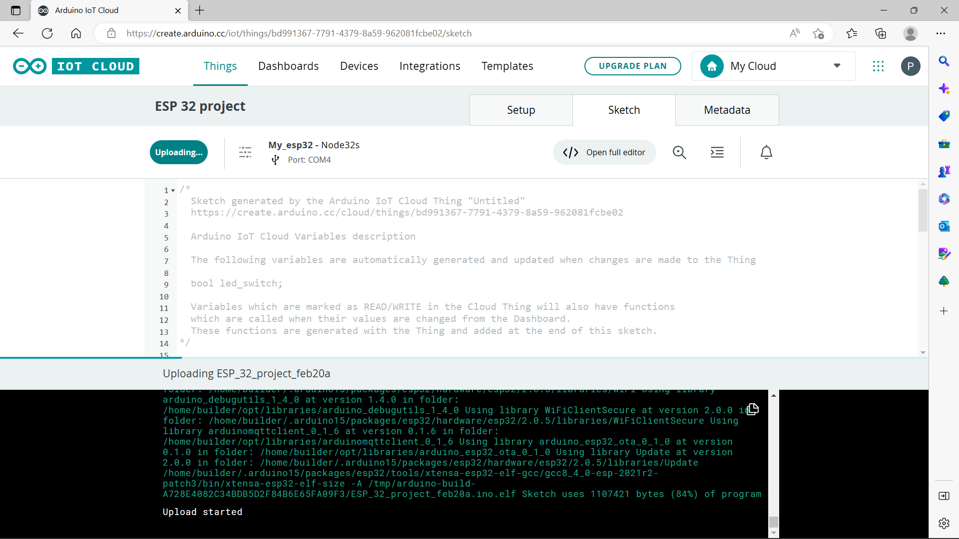
Programming the board The next step is to program the board. To do so, we need to go to the “Sketch” tab and Upload it to the board by clicking on the “Upload” button at the top left corner.
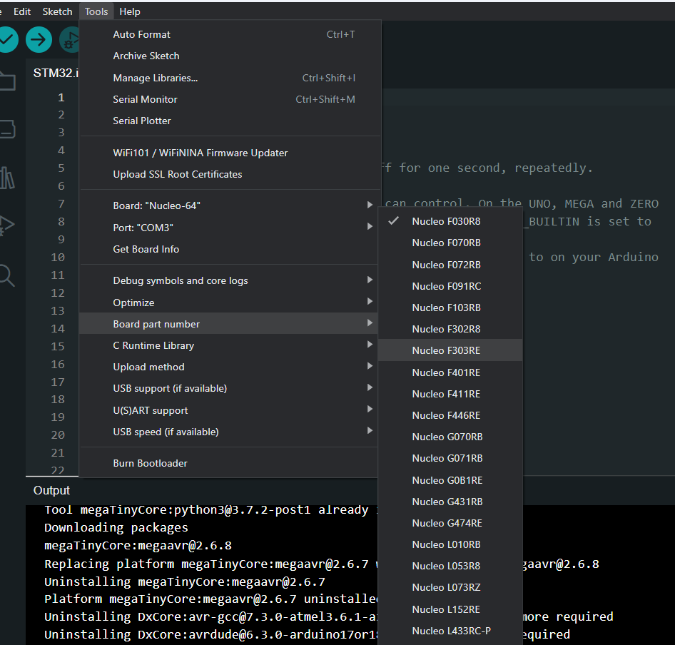
STM F 303 RE
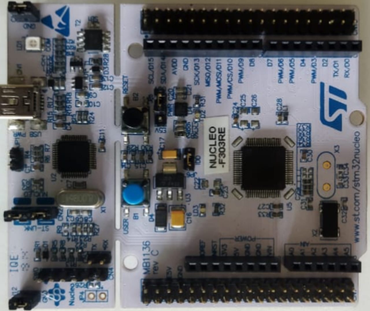
Pinout
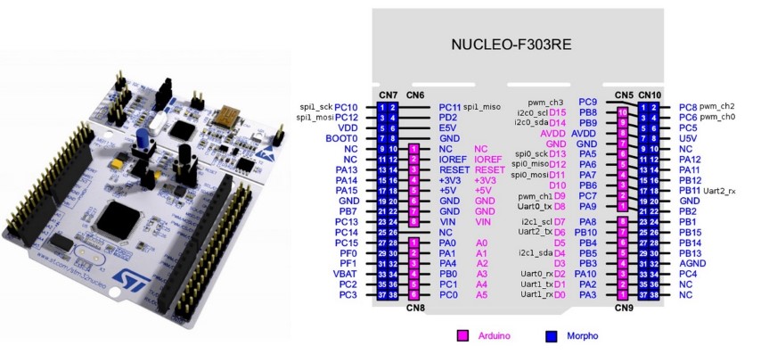
The STM32F303RE is a microcontroller unit (MCU) manufactured by STMicroelectronics, which belongs to the STM32F3 family of MCUs. It is based on the ARM Cortex-M4F processor core with a maximum CPU speed of 72 MHz and features a wide range of peripherals and interfaces
For programing a nucleo board, it is necessary to incorporate the STM 32 Board libraries into the Arduino IDE. For this, got to “File menu” and select “Preferences” , and select Additional Boards Manager URLs
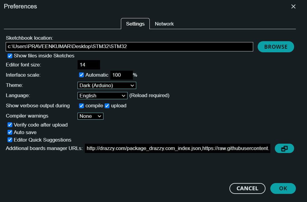
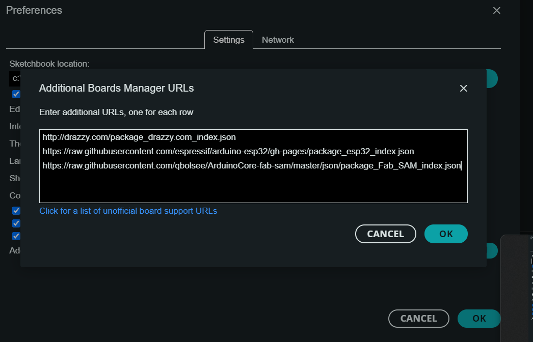
Copy paste the following link on the URL space to add STM32 Boards.
https://github.com/stm32duino/BoardManagerFiles/raw/master/STM32/package_stm_index.json
This will download all the necessary STM 32 boards in to the IDE.
As per the pinout diagram pin no PA5 is th pinmode.