11. Input devices
Individual assignment:
  Measure something: add a sensor to a microcontroller board
  that you have designed and read it.
Probe an input device's analog levels and digital signals.
Sensors
Sensors are devices that are used to measure and detect physical properties such as temperature, pressure, light, sound, and motion, and convert them into electrical signals that can be read by a computer or other electronic device.
Examples of sensors include:
-
Temperature sensors: These sensors are used to measure the temperature of a substance or environment. Examples include thermocouples, resistance temperature detectors (RTDs), and thermistors.
-
Pressure sensors: These sensors are used to measure the pressure of a fluid or gas. Examples include piezoresistive sensors, capacitive sensors, and strain gauge sensors.
-
Light sensors: These sensors are used to detect the presence and intensity of light. Examples include photodiodes, phototransistors, and photoresistors.
-
Sound sensors: These sensors are used to detect sound waves and convert them into electrical signals. Examples include microphones and piezoelectric sensors.
-
Motion sensors: These sensors are used to detect movement or changes in position. Examples include accelerometers, gyroscopes, and magnetometers.
So here I planned to take Phototransistors, cause Iam doing final project in dual axis solar tracking. A phototransistor is a type of sensor that detects light and converts it into an electrical signal. It is a type of transistor that uses light as the input signal instead of an electrical current. When light shines on the base region of a phototransistor, it causes the transistor to conduct more current, which can be amplified and read by an electronic circuit.
Phototransistor
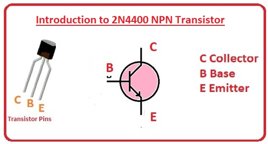
A phototransistor is a type of sensor that detects light and converts it into an electrical signal. It is a type of transistor that uses light as the input signal instead of an electrical current. When light shines on the base region of a phototransistor, it causes the transistor to conduct more current, which can be amplified and read by an electronic circuit.Symbolic reprasantation of NPN type phototransistor is shown above.
SMT Phototransistor
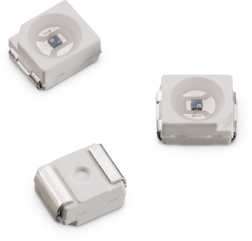
SMT types phototransisitor is show above.This is available on both NPN and PNP type but NPN is the commonly used one. For my assignment I used this type- Osram’s photo diode (PLCC2 package size) which is available in our lab’s Inventory.The (Datasheet.)from conard.com
Phototransistor sensors that change resistance in response to changes in the amount of light that falls on them. In a solar tracking system, Phototransistor can be used to detect the position of the sun and adjust the position of the solar panels accordingly.
The basic idea behind a solar tracking system is to keep the solar panels oriented towards the sun throughout the day, so that they receive the maximum amount of sunlight possible.
PCB Design
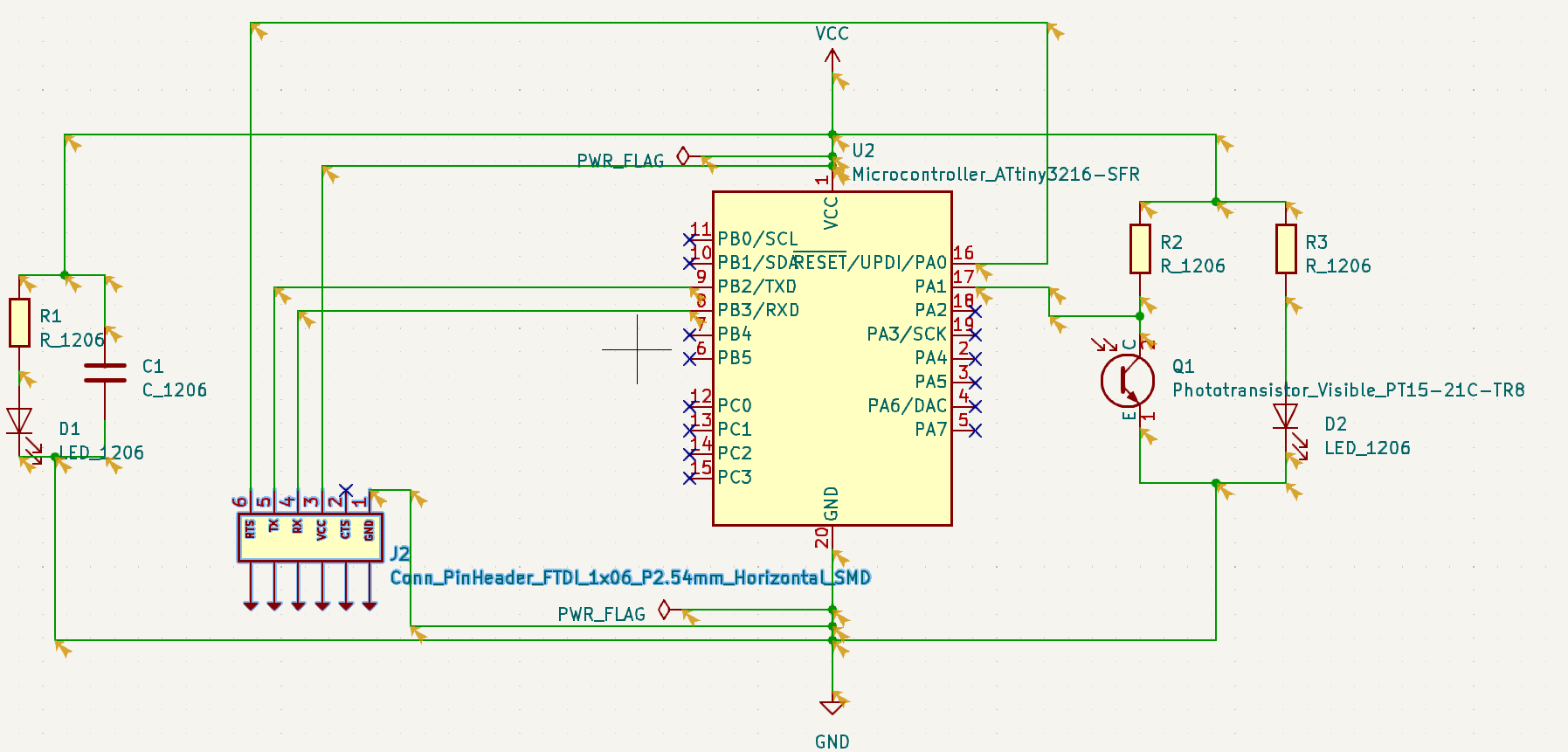
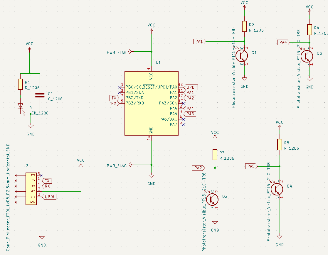
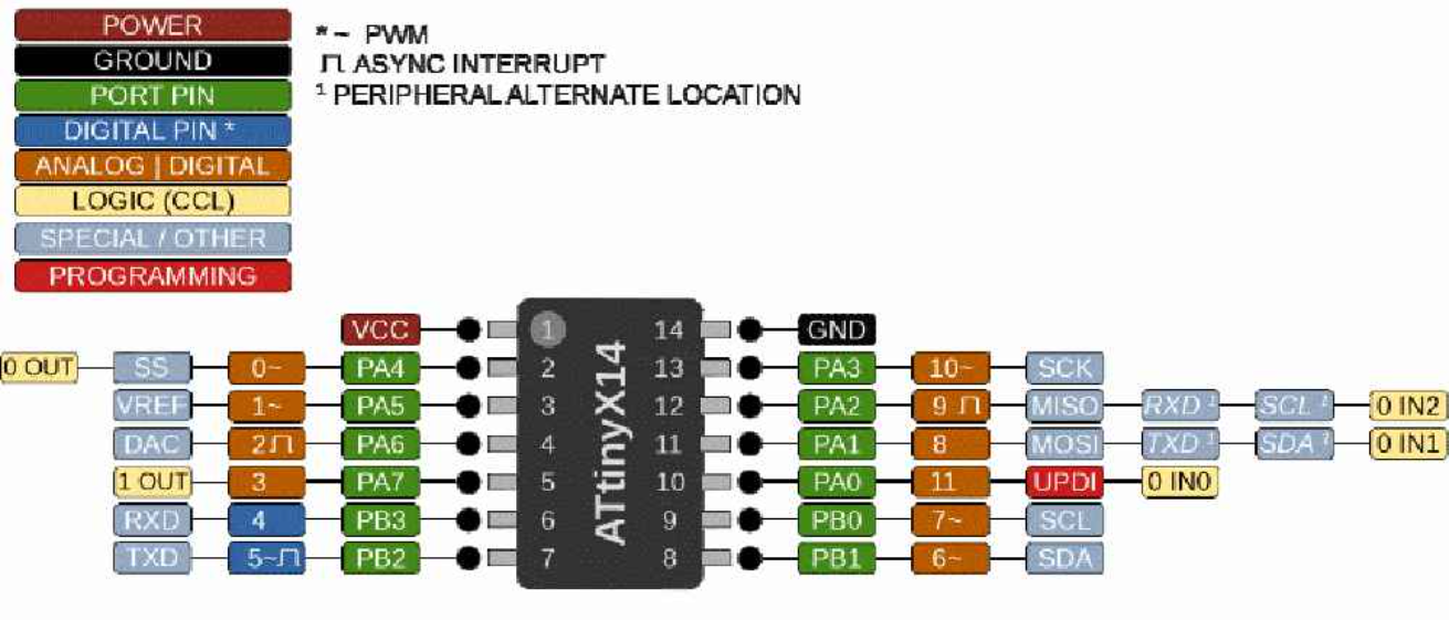
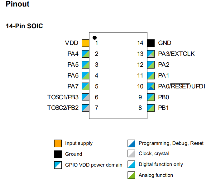
For PCB design as previous week, I used KiCad. Details about how to design the board in ( Electronic Design.) week. Here I planned to use ATtiny 3216 microcontroller and prepared schematic diagram. Since so many pins are not used, I changed to ATtiny 1614 ( Data Sheet.).
The I designed the schematics as follows.
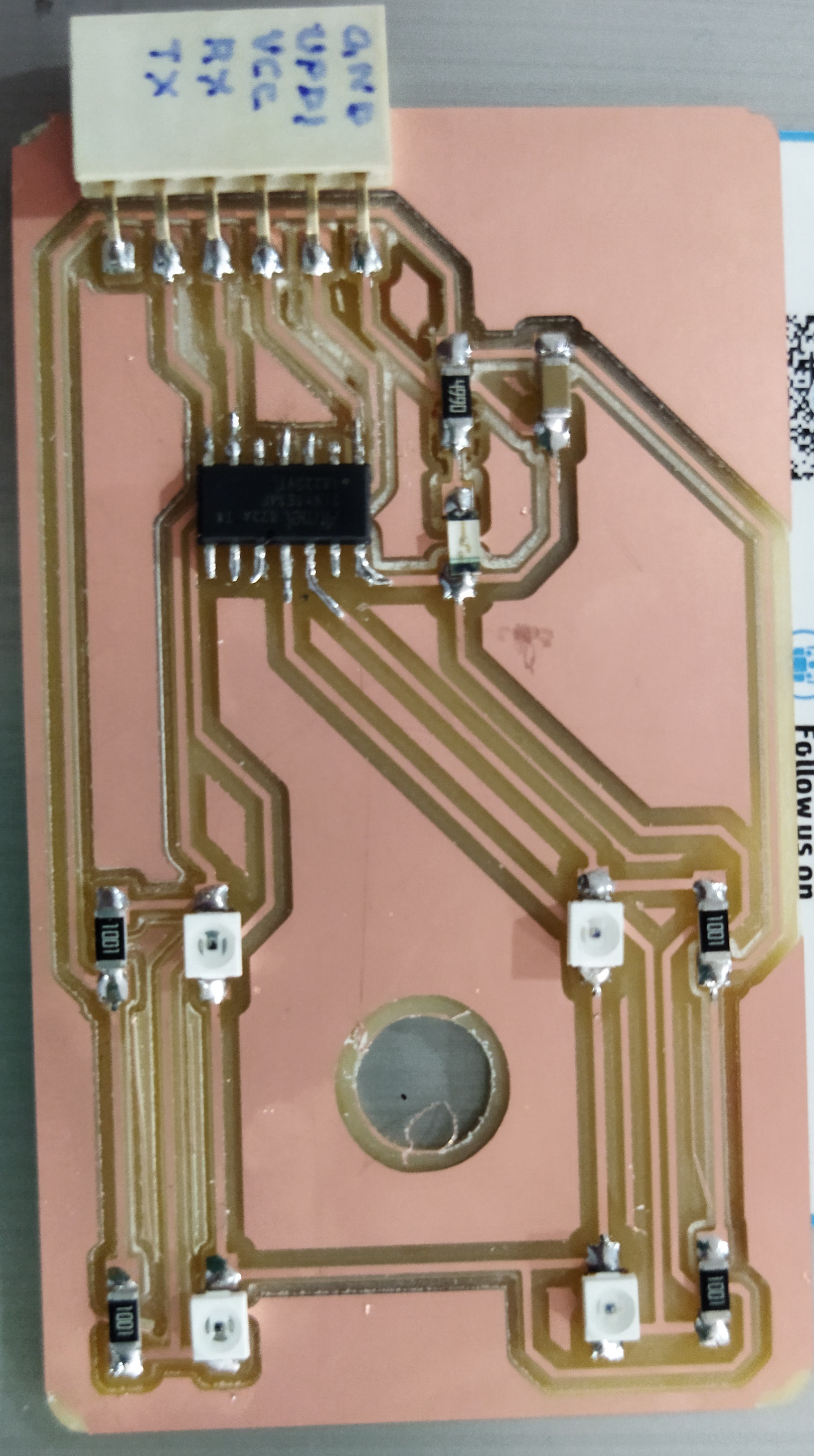
Then I switched to board design followed by setting design rules and then routing the wires, some by auto and some manually finally getting following board
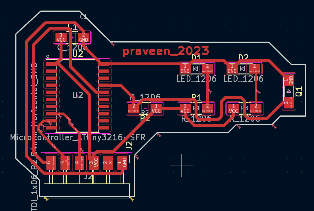
As if now I am proceeding with only 1 phototransistor.Here my friend Mr.Sibin suggested to increase the number to 4 nos insted of 1 as Iam using this assigment to study for my final project. So I increase the phototransistor to 4 nos and I prepared new schematic as well as board.
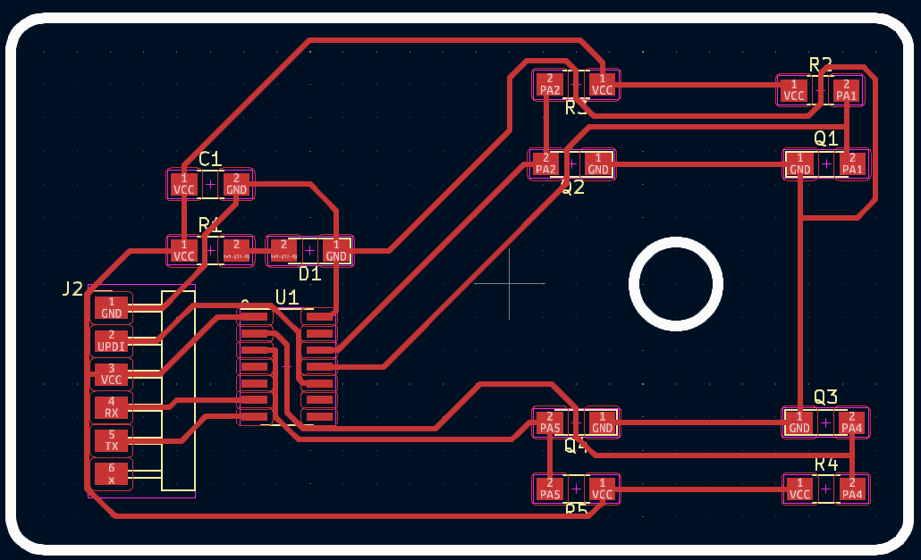
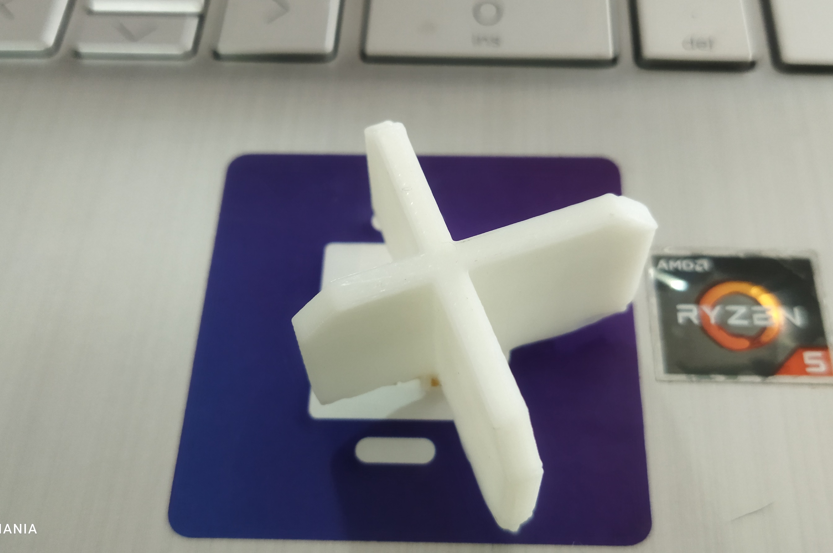
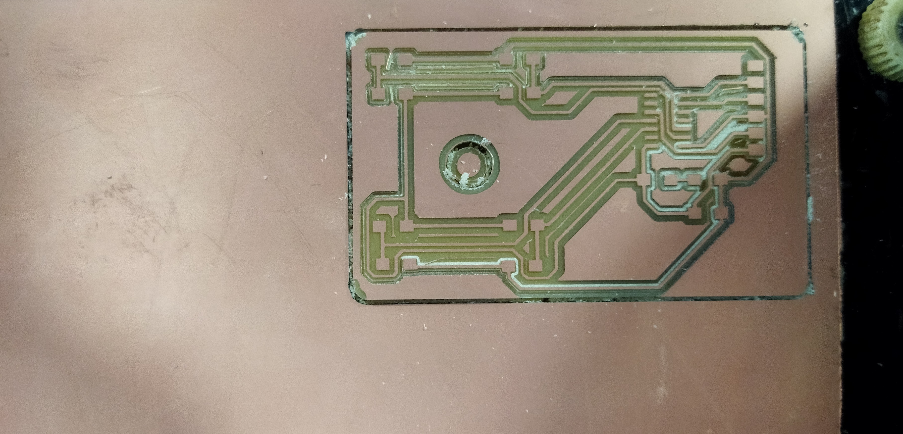
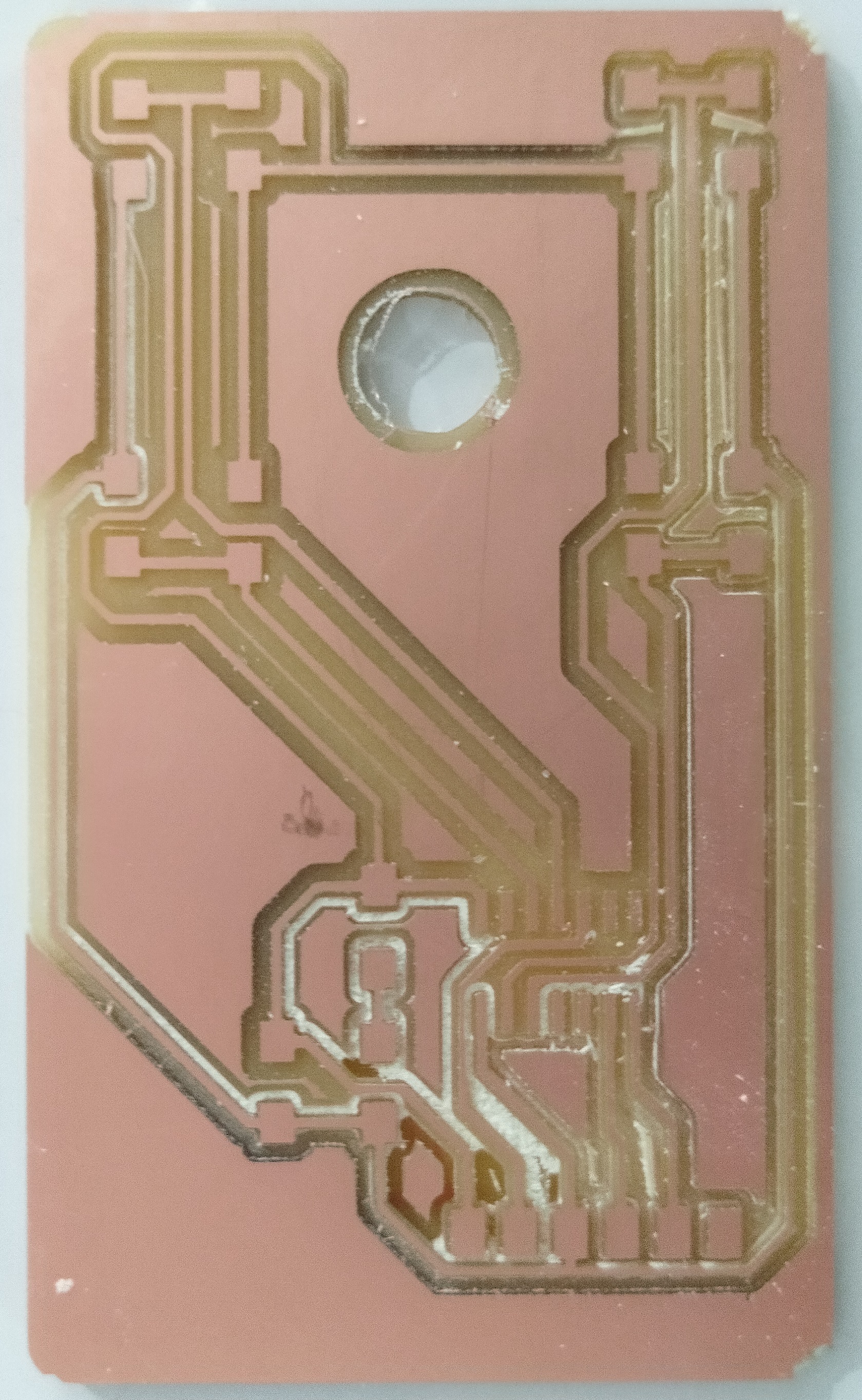
In PCB I provided a hole to hold 3D printed light shied to control the light.
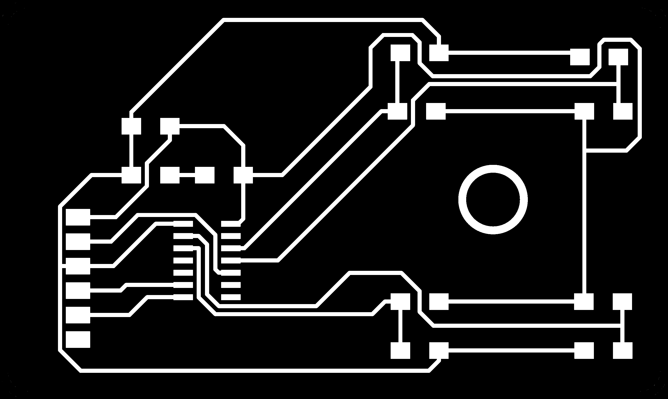
Then the trace image and trim image was exported as follows and then milling was done.

I used the following electronic components.
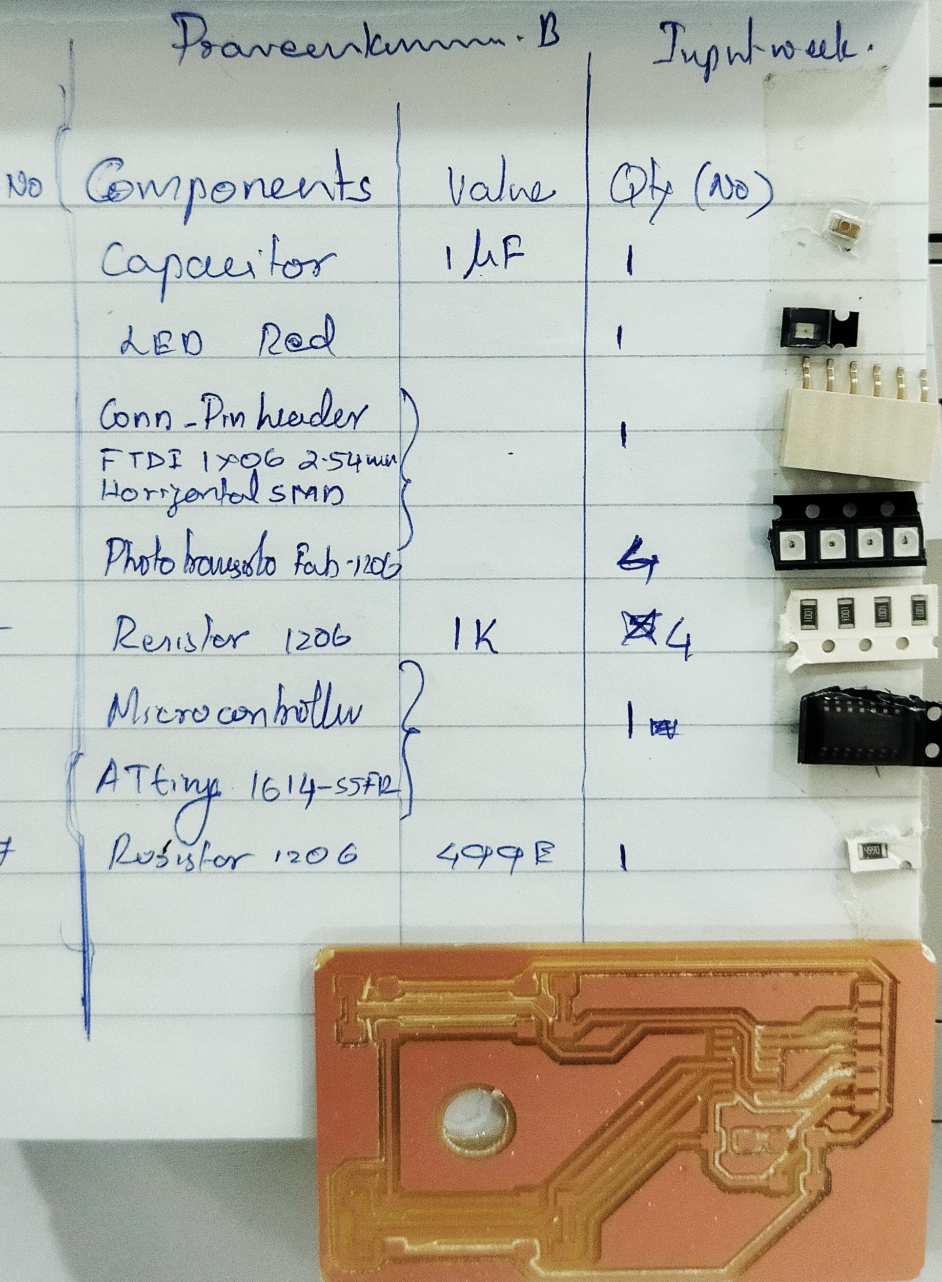
Stuffing the electronic components into the milled PCB refereing the pinout diagram
Programming
Now connect the sensor board with FTDI to load the program. Change the settings in your arduino IDE to ATtiny 1614 and burn the bootloader. Please refer ( here.) for process to burn bootloader.
FTDI
FTDI programmer is a type of programmer used to program and communicate with devices that use FTDI (Future Technology Devices International) USB to serial ICs (Integrated Circuits) such as the FTDI FT232R or FT232H.
FTDI programmers are commonly used in electronics and embedded systems development to communicate with and program microcontrollers, development boards, and other devices. They provide a simple and efficient way to communicate with devices that use a USB to serial interface, allowing developers to quickly test and prototype their designs.