Mechanical Design and Machine Design
Group assignment:
- Design a machine that includes mechanism + actuation + automation + application
- Build the mechanical parts and operate it manually.
- Actuate and automate your machine.
- Document the group project
Individual assignment:
- Document your individual contribution.
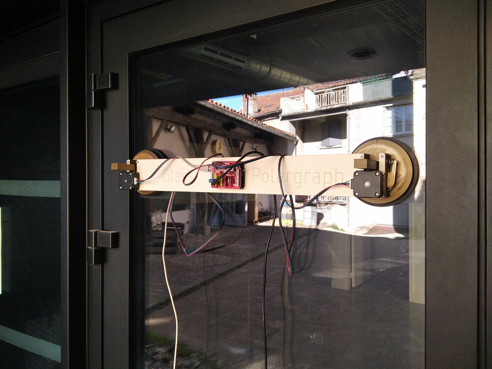
A polargraph/XY plotter drawing on glass machine
As I said in the previous weeks, I'm following the Fab Academy remotely. My Node is Kamp-Lintfort in Germany, and this year we are 3 students to follow the class:
- Lisa Schilling (Based in the Kamp-Lintfort, Germany)
- Uwe Terton (Based in East Coast, Australia)
- Me (Base in Caylus, South-West of France)
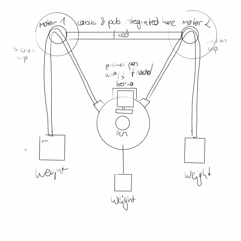
We decided to still try to build together a machine. But as we are only 3 and not together, we went for a simple machine: a Polargraph. It's a 2D drawing machine with to motor at the top and a pen connected with two strings/belts.
Just, to be a bit more original, we decided that the motor will be held to window glass with some suctions cup so it can draw on windows. Here the Glass-polargraph.
Here is the first draw made by Lisa Schilling for the team.
Ressources
Polargraph or Vertical plotters are pretty common and there are plainty of documentation. Are is a list of inspirations for our project:
- stefanopadoan art
- MertArduino
- MTvplot
- Sandy Noble's Polargraph
- Artigiano 2.0
- grbl-polargraph
- Janos Noll's Polargraph
Bill of materials
As we need to work remotly, I had to agree on the material first so we have similar product to work on.
Here what I get:
| Components | Quantity | Cost Unit | Ref | Total Cost |
|---|---|---|---|---|
| Stepmotor bipolar (4mm axe) Type NUMA17 | 2 | 10,99€ | 17HS4023 | 21,98€ |
| Shield with drivers type A4988 | 1 | 23,99€ | CNC-Shield V3 w Arduino UNO | 23,99€ |
| GT2 belt pulley (5mm axle and 20 teeth) & rubber belt | 1 | 15,99€ | TUZUK GT2 kit | 15,99€ |
| Servomotor | 1 | 9€ | SERVO DM996 | 9€ |
| Suction cups | 2 | 7,82€ | Vorel 05311 | 15,64€ |
| Extension cable 4 wire (for the I2C + 5V + GND) 5 meter | 1 | 1,2€ | LEADTOPS LED RGB extension | 1,2€ |
So the total cost of the Glass-polargraph is 87,80 €.
Frame for the Glass-polargraph
So let's start by designing what will support the motors and the electronics.
Suction cut in 3D
First Uwe worked on -3D modeling the suction cup. His work is available here.

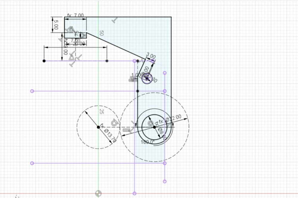
I try to think about How to fix the motor on the suction cup. I made some drawings, based on the dimension of the suction cup of the Bill of Material.

So the idea was to redraw all the suction cup bases and just take the rubber piece for the original suction cup.
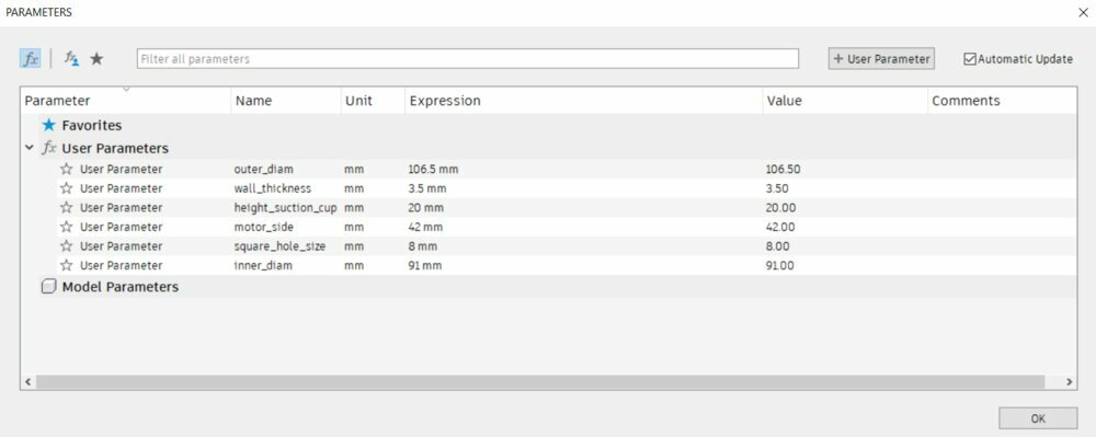
So first I create the first parameters. All along the way I added variables as I needed them.

So I quickly created a cylinder with the outer diameter and then a chamfer of
( outer_diam - inner_diam ) / 2.
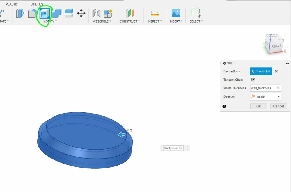
Then I create a Shell with the wall thickness.
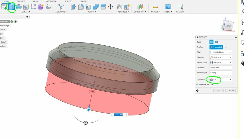
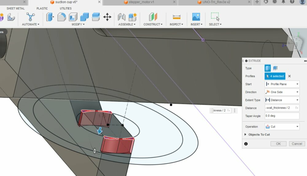
I use the Extrude function to cut the hole a the bottom by selecting the inner bottom face inside of the body.
Add the square for the rubber' stem.
Motor support

I wanted the support motor to be independent of the suction cup base. It's gonna be easier to iterate and test. And also know the limit of 3D printing, I prefer to print without support. So I design my piece to be printed without them.
We can see on the draw that there will be some lateralization between the left and right. For example the need for the belt moving from 90°.
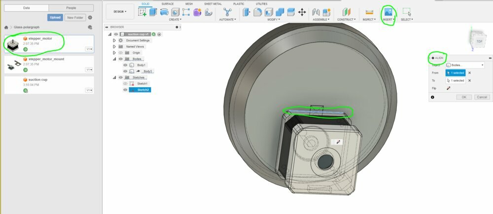
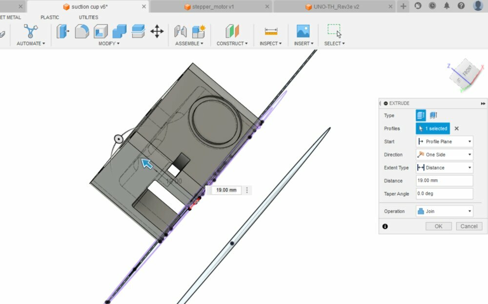
I then Imported the 3D model of the Stepper motor NUMA17 made by Uwe and align the top of it with the middle of the cylinder.

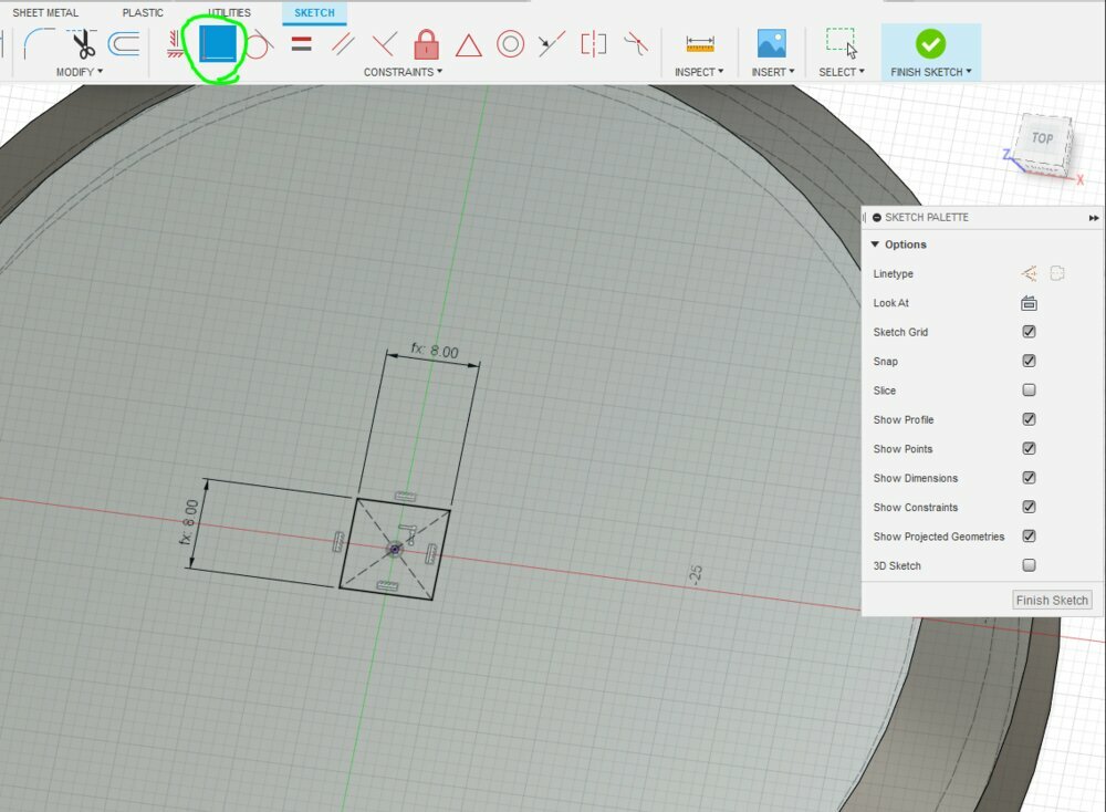
I then project the face of the motor on my sketch to have all the holes and edges of the motor.
The idea behind this is that the design stays linked with all the components. So If we edit the stepper motor, it should update the design of the support for the motor.

With that I created the hole to pass the futur screws.

And the extrude the support fo the motor with the follow height: screw_length - wall_thickness - motor_bold_depth. I create a new body as it will be 3D print separatily. (I want to print without support). It's a 3 legs support as the belt will need space to move 90°.

I then added a face to be able to fix the entire motor as I have some room to do it.
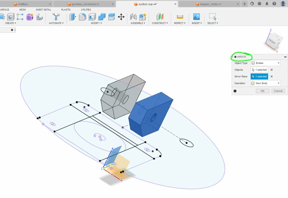
I had also to create the Handle that Up the suction cup as with the motor support, the original one doesn't fit anymore. I quickly draw one part of the end-handle and mirror the other.

For the final shape of it, I keep it simple. Just a simple rectangular parallelepiped as I may need space around. I could still make it more ergonomic later.
Add arduino board

The idea will be to fix the Arduino on the link between the suction cup. First I saw that we can insert 3D part already modeled. But we need to pay for it.
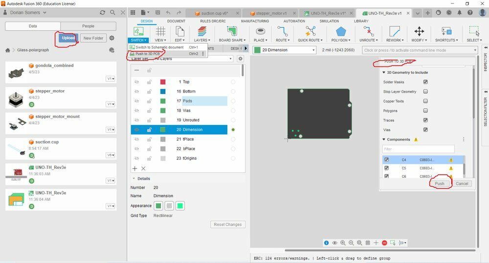
In Arduino's doc, we can find the CAD files of the Arduino Uno Board. There is an Eagle file that can be open with Fusion360.
In Fusion, we can then push the board to 3D PCB.

There I saw which body I need to have the fixation holes.
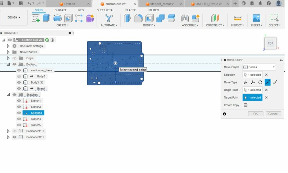
This body can be inserted into the section cup file. And then move to the center of the link for a future projection of the fixation holes.
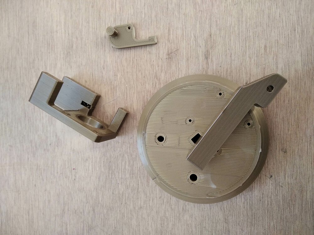
First 3D prints.
Before finishing the link, I wanted to try to print some of the pieces to check the defaults.
I just exported the 3 bodies in .stl and then slice them with Cura. I choose a of infill, a gyroscopic infill of and a nozzle of .
The motor fits perfectly on the support, and the dimensions of all the pieces look great.
But here is the first mistake: because the bolt that fits on the stem's rubber is in the middle, I can't push it because of the motor support.

I took advantage of the 3 legs to try to fit the handle and do a first try on a glass.
First comments: 10% infill is not strong enough the pressure is too high and the plastic bends.
Second one, I could actually try to put the support on the top of the suction cup like this.
Last one, I will need something to hold the belt on the gear. So I need like a bearing to push the belt on the gear like here.
Redraw the support
So let's modify the design.
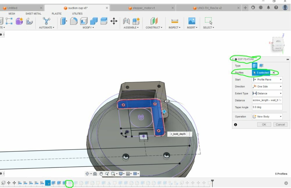
What's nice with Fusion 360 is that we can go back on the history and change a feature. So it's what I did.

When editing a feature, it can break some links, and references in other features. So I had to go back to some of them to fix it, like for the Filets.
Then I started to work on the arm that will push a bearing on the pulley. There will be a spring on the other side to hold it.
I created a small part to will fit on the top of the spring.
And then a small intrusion on the support to host the base of the spring. I also add an extrusion on the hole for the arm as I don't want to print with support. I'll remove it after the print.

But while redrawing the support and looking at the first print, I realize that by putting the motor at the top position of the suction holder, I'll have a problem with the belt. There is no room for it to move in both directions...

So let's go back to the drawing table. Here is what I want to try.

And here we go ! Now I should be able to fix the handle.
Print the new version
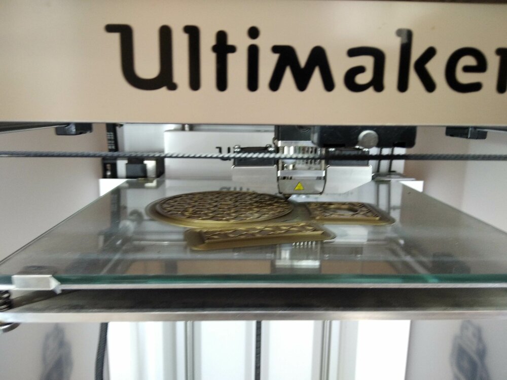
Here are the pieces printed.
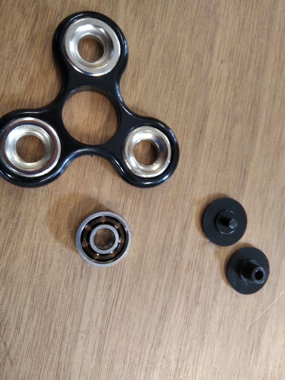
We received a lot of fidget spinners at the lab. So I decided to reuse the bearing inside for my use =D.
It fits perfectly! 🤩

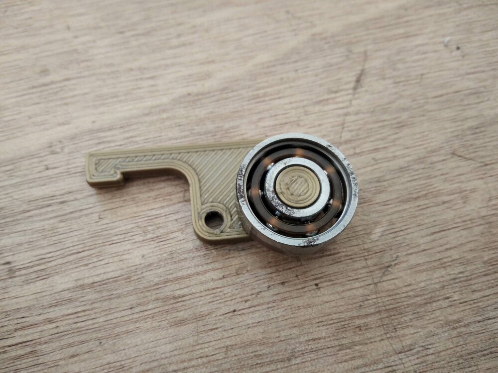
In my new motor support design I have 6 holes instead of 4. I didn't want to reprint a hole new suction cup base, so I reuse the first one, by just drilling the missing holes.
As explained before, for the hole in the support that will host the arm for the bearing I made a small support. It didn't go well, but it's more than enough to test.
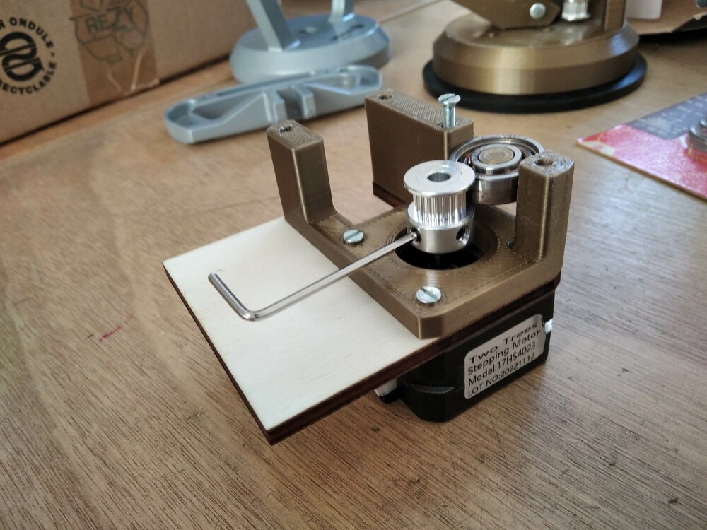
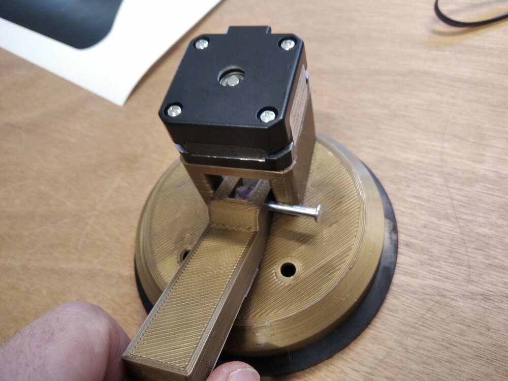
I started to mount some components and the bearing. I also need to add the pulley as I won't be able to do it later.
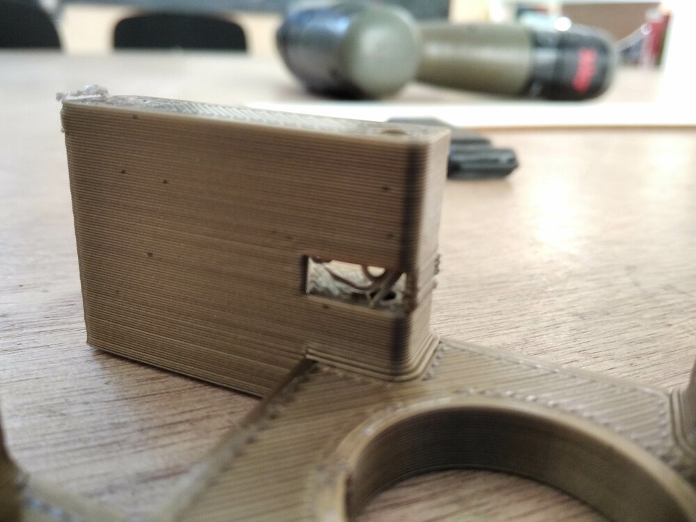
 ... And then... a mistake again! While editing the feature a creating the new motor support I forget to let enough room for the handle to lift up. (Something I did on the first design). For now, I will just cut into the plastic to let the handle pass.
Cut link

I also finish my link between the 2 suction cups. For the test, I will cut it into white cardboard, to not waste plywood.

It's promising.
Results
Here is the result, it's really good for a first design. Quick, I need a Gondola now!

Gondola
So the gondola is the holder of the pen, it will be connected with two belts to the stepper motors.

To start the design of it, I had to see the distance between the belt and the future glass. For my design, it's .
Gears
First I had this idea that the gondola could be able to move the pen backwards and forwards. So for that, I will need some gears to move the pen with the servomotor. I followed this"how to make gear" in Fusion360 tutorial.
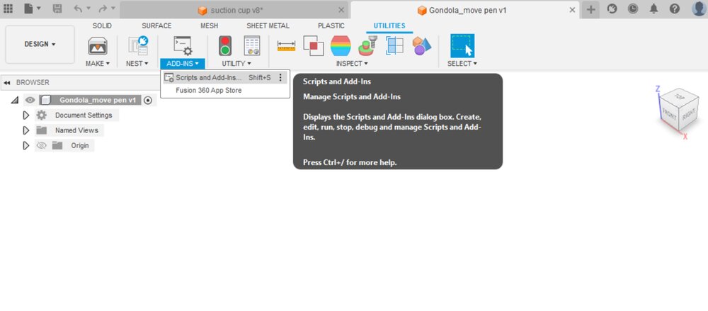 So first I went to the ADD-INS menu.
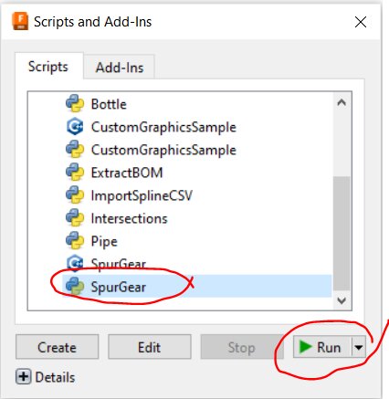 There I found the SpurGear Python script. You can just run it with the parameters you want.
 Once the sketch was generated, with an extrude I had my first gear.
 now I need a linear gear to move up and down the pun. So I just made an offset of one tooth, then I was able to create a linear pattern to repeat the teeth vertically.
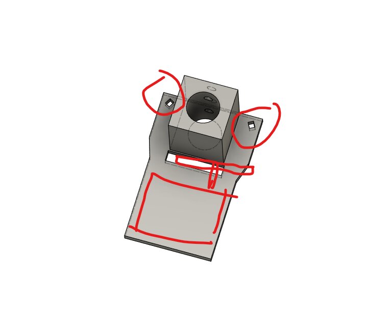
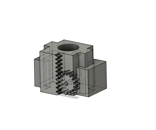 Here is the result with the pen holder.
Belt holder
My first idea was to not cut the belt and 3D print and negative of the belt, so I could clip the belt in it.

source alibaba.com
So I first found the measures of a 2GT belt.

Then I place that semi-circle on an arc.

Here is the first result. The belt will be attached with a spring of a clothespin. So let's print that!

Here we can see how the pen is fixed.

I was naive... Actually, moving the pen backward and forwards is moving the center of gravity too...
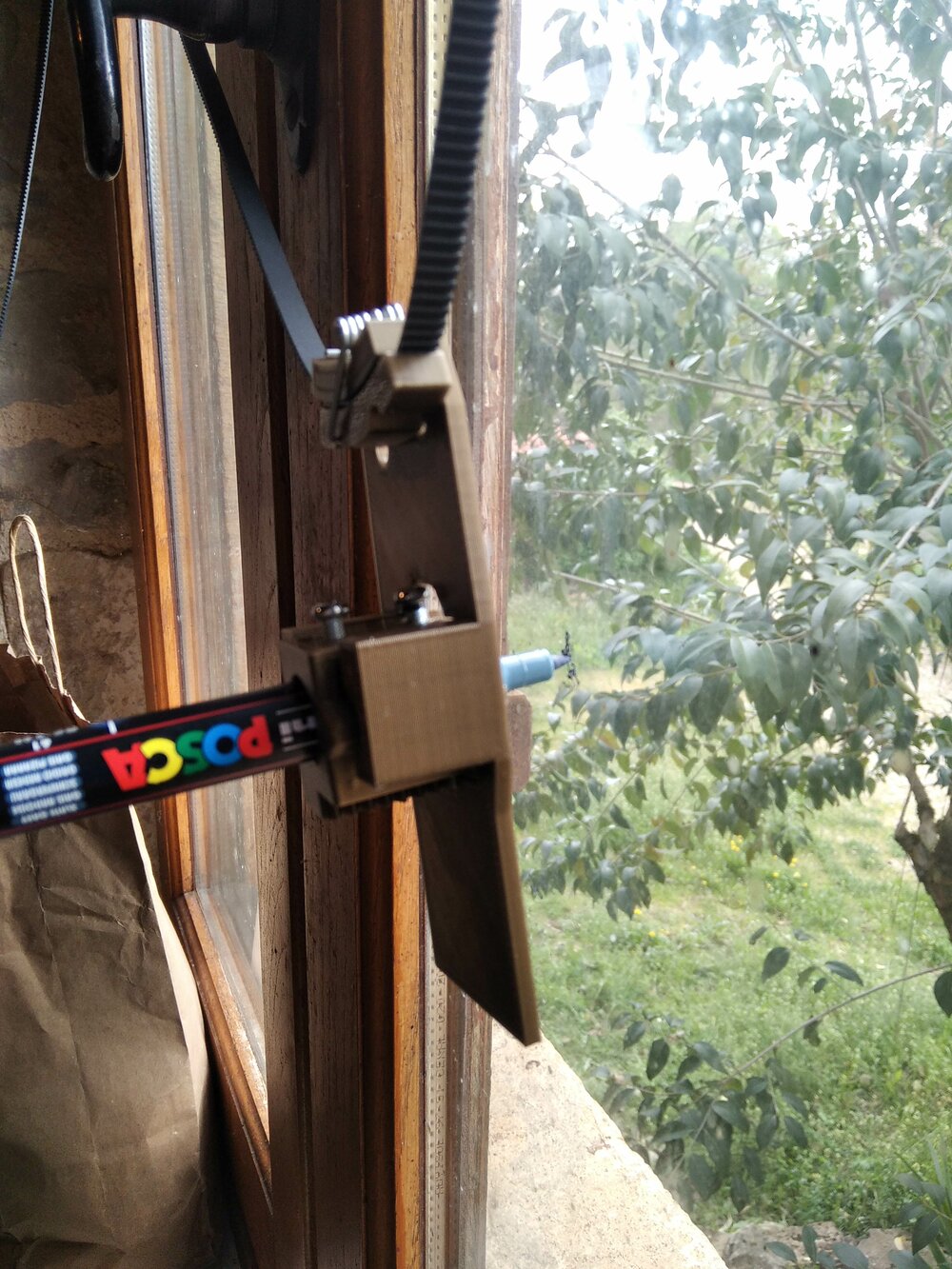
So when it's backward it's touching too. I won't take the risk that this gondola won't work. So let's try something else.
Gondola V2
So I decided to try something more basic. Two belts and a place for the servo.

Here is the print. The servo is fixed with double tap and the belt with rilsan collars.
I hoped that the weight of the servo will be enough (it's a "big one" for a small servo), but is not. So I will a better gondola, but let's go on the electronics part.
Gondola V3 - final
After the fail of the GRBL Polargraph I went back on the gondola.
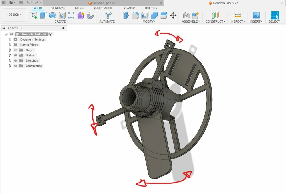
Inspired by this gondola made by Mark Benson (CC-BY-NC-SA), I recreated a gondola where the fixations of the belts can easily move, a place to put weight and a place for the servo.
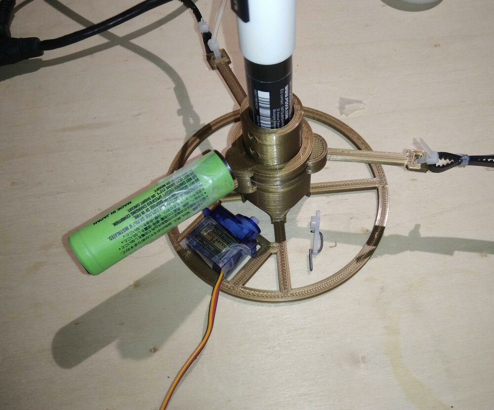
Here is the result of the gondola. This should work fine.
Electronics
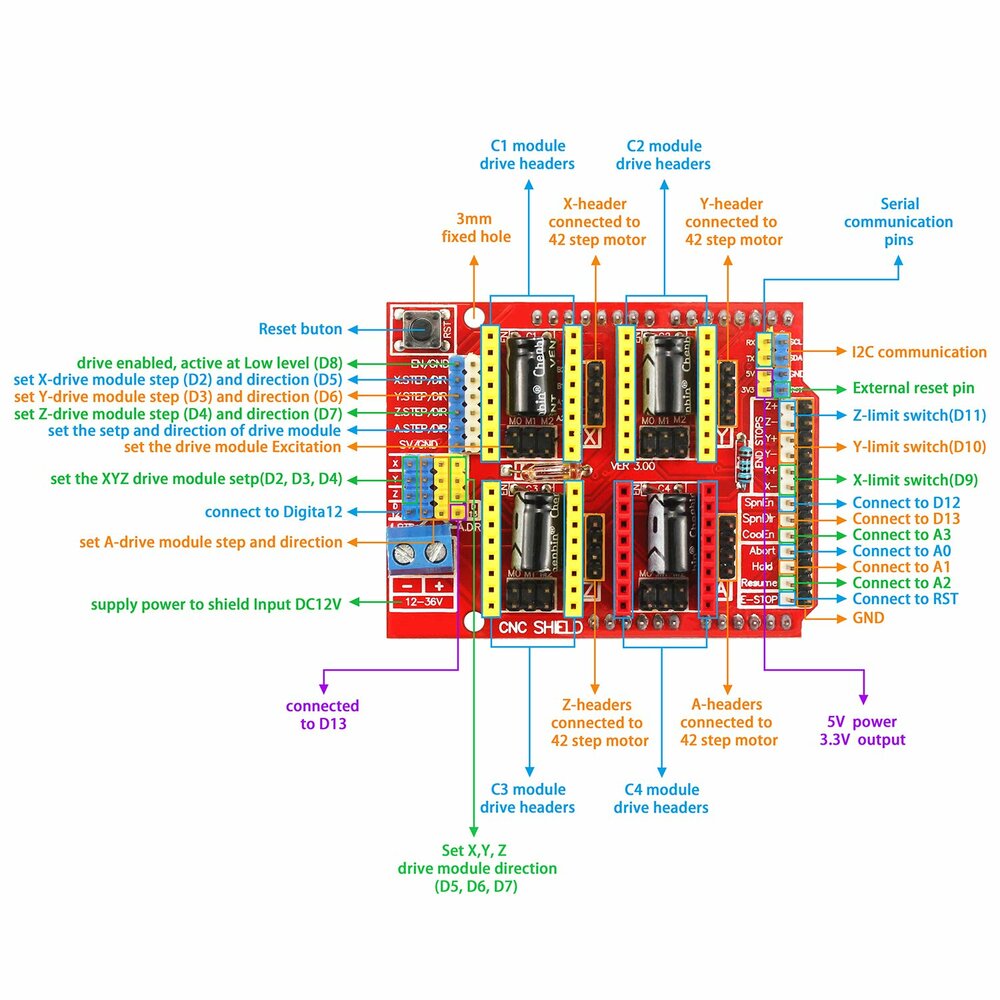
source forum.arduino.cc
As seen before, I'll use a CNC Shield V3, it's an extension card for Arduino UNO. The drivers for the stepper motors are A4988, able to do up to 1/16 micro-steps.
Power supply
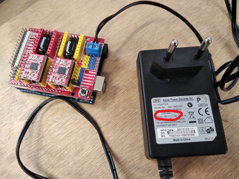
The "CNC-shield v3" need 12v and so do the motors. I had to connect an external power supply (the Arduino is not enough). The first power supply I had was able to give only . The motors I have (Nema 17hs4023), need per phase and I have 2 motors so I need minimum1.
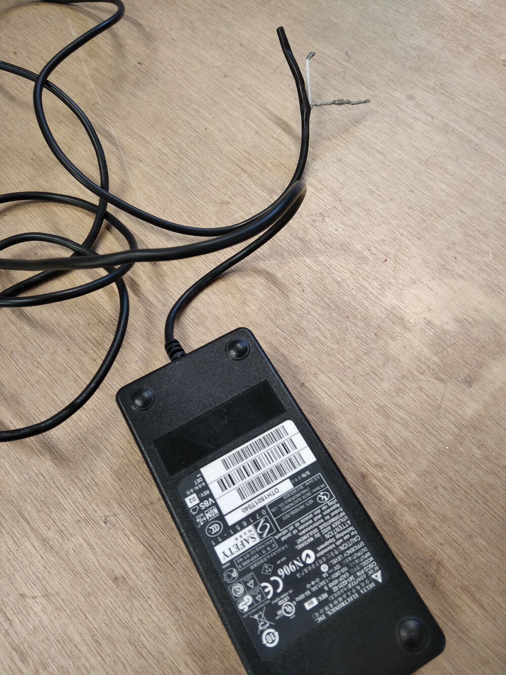
So I found this one, that can give till . The end wires are a bit ugly.

With some insulation heat shrink tubing. I was able to make it a bit prettier.
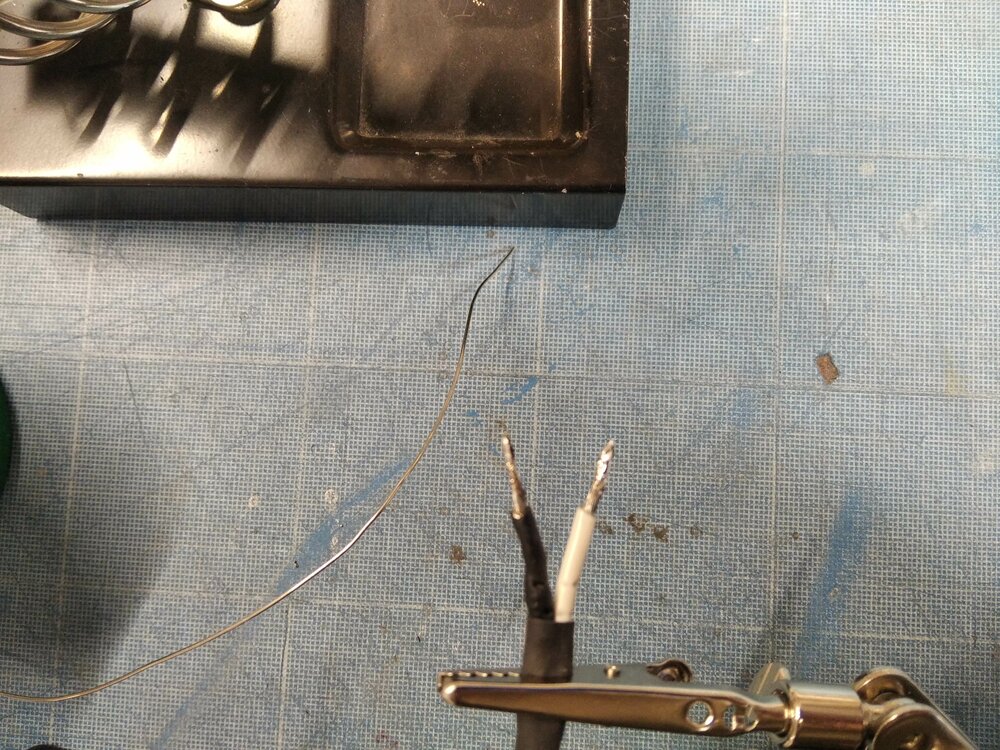
I added some soldering at the end to be able to put on the shield more easily.
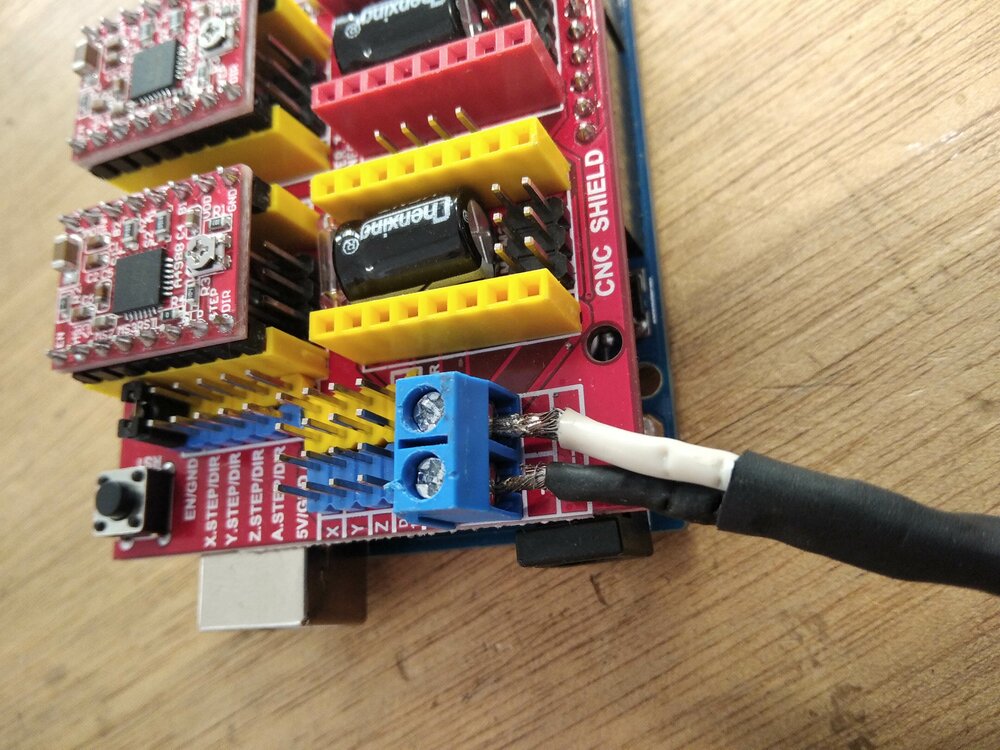
Here we go, I have power now.
Servo cable extension
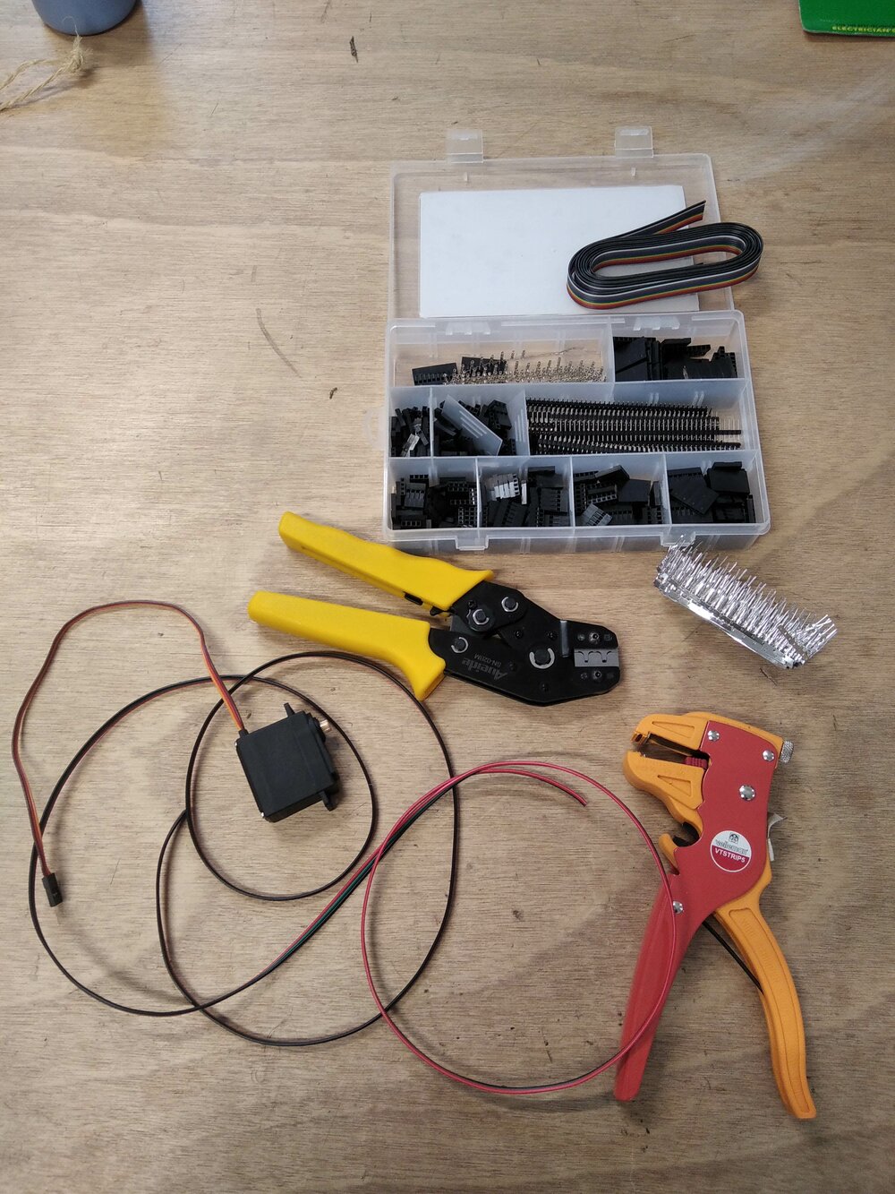
The cable of the servo motors is way too short to be connected to the shield board from the gondola. So I decided to add some Dupont connectors to a long wire.

Here is the new connector. The colors of the wires are not the same, but if the reds are connected, so it means it's good. With this configuration, it's easy to plug and unplug.

I also add a small rigid metal wire to help the servo touch the glass and pull up the pen.

source sibusaman
As the servo can take too much current from the Arduino board when connected to USB, the idea is to power the Arduino from the 12v. Here how I did it.
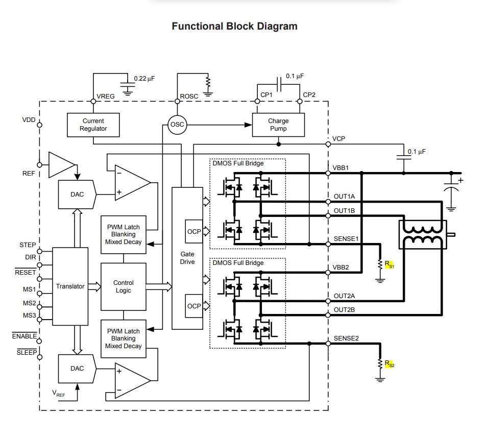
Current limit on driver A4988
The motors can't handle to much current. So it's safer to set a current limit via the drivers. Following this tutorial, I had to set this limit using the potentiometer on the driver module.
source allegromicro.com
In the tutorial they use this formula:
.
We can found where are the current sense resistors in the datasheet of the A4988 driver module. The rated current is per phase. But I found another source with per phase.

If will look at the module we can see that the resistors used have an R100 code. It means 2. So we have . But in the datasheet we can read "It is critical that the maximum rating (0.5 V) on the SENSE1 and SENSE2 pins is not exceeded." So let's set the to . In the picture, we can also see the small potentiometer that can be screwed to change the value.

To change the value, I just connected the screwdriver to a multimeter while moving the potentiometer to select the right value.
Final touches

In my design, I forget to add the thickness of the washer to the suction cup. To be able to fit it I had to cut a part of it.

Here, in its new place.

I decided to remove the link between the two suction cups as I want to be able to adapt the width of the polargraph to the window I'm drawing to. The distance between the two motors will be set in the firmware. I add a small R to know where to put the motor.
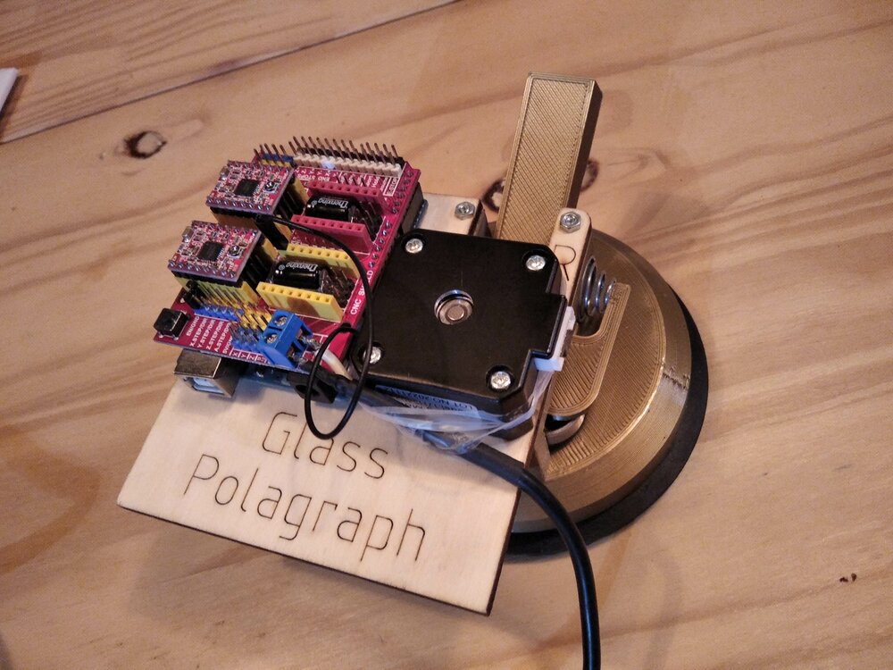
And here is the result in the picture.
GRBL Polargraph
I could use a fork of Marlin as firmware, but GRBL seems to be a clever way to go with an Arduino UNO and a CNC-Shield V3.
Firmware
I first found this fork of GRBL for polargraph inspired by another fork of GRBL (both GPLv3 license). I flashed it on the Ardunio UNO. But it didn't work. That repo is using a CNC Shield V4 with an Arduino Nano.
After some searching in the code, I found that I could comment and uncomment the lines in the grbl/congif.h file for the Arduino UNO.
#define CPU_MAP_ATMEGA328P // Arduino Uno CPU
//#define CPU_MAP_POLARGRAPH // Polargraph with Nano and CNC shield v4
After pushing the code, with the help of UGS I was able to move the motors ! 🎉
UGS - Control the polargraph
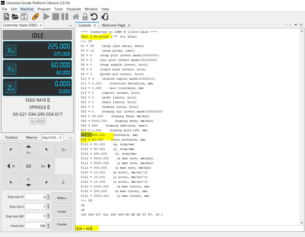
UGS stands for Universal Gcode Sender. It's a software (GPLv3 license) that can be used to send G-Codre to CNC controllers. It supports GRBL. Once open, and the board connected, I just had to select the COM and the baud rate and click on connect.
When connected, the console is showing the parameter of the controller. There are two important parameters: the distance between the 2 motors and the vertical distance. For the first one, I measured the width and reset the parameter like this: $28 = 650 where the distance is in millimeters.

The gondola will never be at the same level as the motors, the tension would be too great. So the difference in heights is called the vertical distance and is the parameter $29.
On my first tests, I saw that the motors were going in the wrong direction.
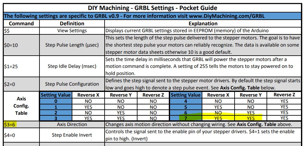
source diymachining.com
With the parameter $3, I can easily switch the direction of X, Y or both (0, 1, 2 or 3). The other solution is to turn the connection of the cable on the board 180°.

Following this tutorial I discovered that we could use a plugin, called Gcode Plot, in Inkscape to directly generate some GCode following a simple path.
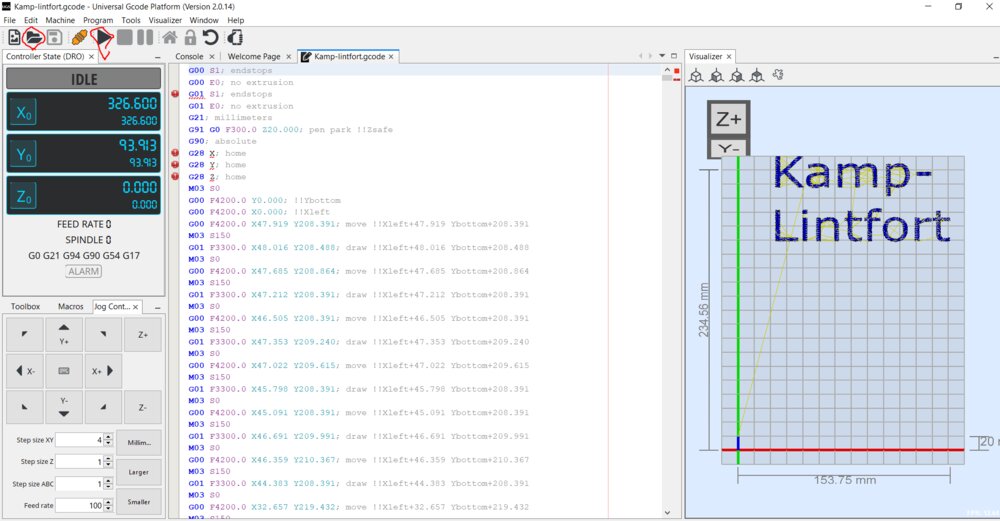
I had my GCode, I open it in UGS. I could already see the result on the right panel. I try to run it, but It went all wrong. It looked like the distance was right at all.
After hours to check where the errors were comming from, testing all the possible steps/mm value ($100and $101) For a full step with 20 tooth gear and a GT2 belt and 200 steps/revolution the value should be . But it still doesn't work. So I decided to go back to the gondola and maybe try another firmware.
Polargraph Controller
As I struggled to make GRBL work, I decided to give a try to Lisa's method using Polargraph Controller. I use her steps to install the Library on Arduino IDE. I also checked this machine-building week from Singapore

Once installed, I could launch the processing sketchbook Polargraph Controller. First thing, it was not automatically detected, I had to select the right Serial port in the Setup tab.

Then I wanted to see if the Servomotor was working in the right direction by default. And it wasn't, so I had to move the servo, the other way around.
With the default option from the polargraph server, my motors were not moving. Then I found the Polagraph-FAB15 Project, it's well documented. I decided to install its version of the Polagraph firmware and followed the installation and there it was working!
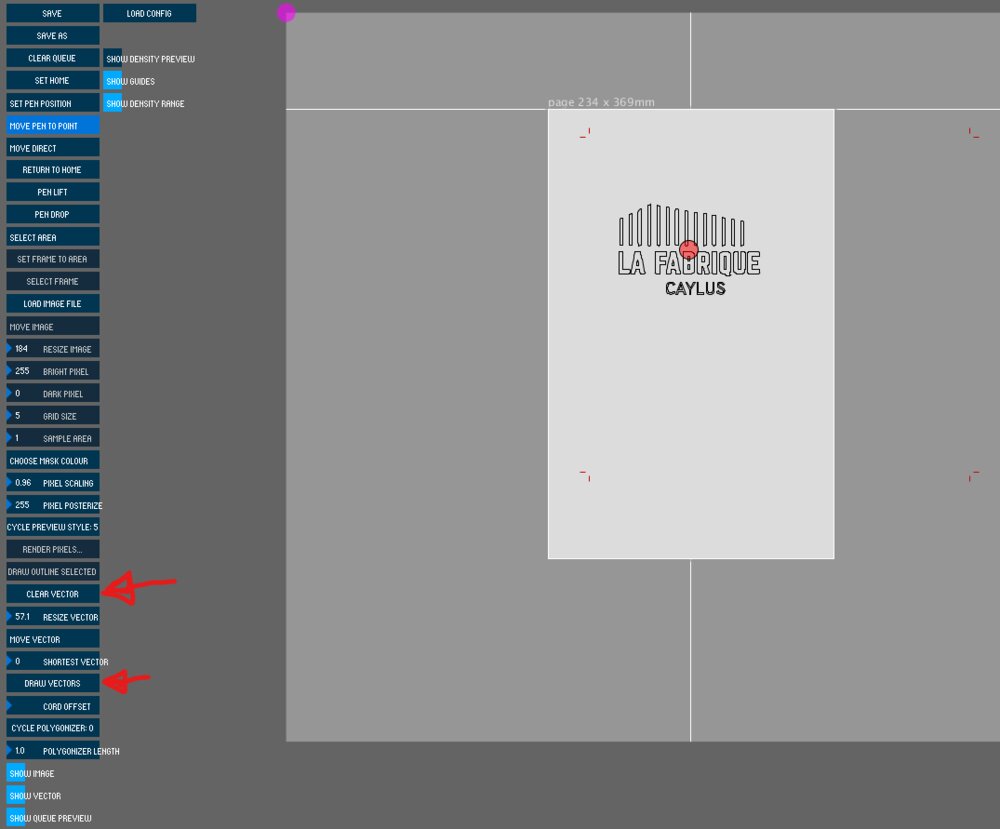
After I set the width between the two motors and the vertical distance in the setup tab (a bit like for GRBL-Polagraph), I could go back in the Input tab and import a vector. I imported the logo of my fablab.
After I clicked on DRAW VECTORS it finally started to draw!

The result is pretty bad. The belt moves during the process so I get some overlaid texts. I will stop here, as I spend already too much time on the group project alone. But the next spiral is to add some weight to the belt, it looks like my "spring bearing" is not enough. I could add some jumper to activate the micro-stepping to have something more smooth. (With the full step it's vibrating a lot).
Files
Here are the files of the week:
- supp_motor_right.stl
- arduino_supp.dxf
- gondo_arm1.stl
- gondo_arm2.stl
- gondo_arm3.stl
- gondo_base.stl
- Gondola_base.stl
- Gondola_base2.stl
- Gondola_belt_hold.stl
- Gondola_gear.stl
- Gondola_pen_supp.stl
- link-laser.dxf
- suction_cup.stl
- supp_bearing_left.stl
- supp_bearing_right.stl
- supp_motor_left.stl
- Look for the datasheet https://duckduckgo.com/?q=17hs4023+datasheet↩
- thanks to this converter: https://kiloohm.info/smd4-resistor/R100↩