Mechanical Design, Machine Design
Group assignment: Part 1
Group assignment: Part 2
Individual:
Group Assignment
Idea: Polargraph
Polargraph controller Copyright Sandy Noble 2018. http://www.polargraph.co.uk/Our team member Dorian
had the idea for a wall drawing machine.
This wall drawing machine, sometimes also known as a polargraph , is a type of robot that uses two
stepper motors to move
a pen or marker along a vertical surface,
such as a wall or a large sheet of paper. The motors are controlled by a computer program that
sends commands to adjust the length of two strings,
which are attached to the pen and run through pulleys. By varying the length of the strings, the
motors can move the pen in any direction
on the surface. The computer program can be controlled by a user, who can draw images or text
using the machine.
The special feature about our wall drawing machine is that it can be put onto windows/glass via
two vacuum lifting tools on each side.
Making it useful for reating any glass art and especially for
writing text or art on the display windows of shops.
Work distribution
Since we're all living very far apart (France, Australia, Germany) we can't work on the machine together in person. Therefore, we're building multiple versions of it at our own Labs with our own small twists to it. Throughout the process we did several meetings and collaborated on a Fusion project. We shared our progress and ideas for the project and it's outcome. That's why we don't have clearly divided tasks, but we are all helping each other throughout the whole process.
Design & Assembly
Note: Dorian and Uwe created a 3D design of the plastic part of the vacuum lifters which already has an integrated stepper motor bracket. I have slightly different sized vacuum lifters plus I also wanted to produce the prototype as fast as possible, so I used existing 3D models for the brackets and the gondola from the web and mounted them using screws.
| Component | How Often Needed |
|---|---|
| Arduino UNO | 1x |
| L293D Motor Drive Shield | 1x |
| L293D Motor Drive IC | 2x |
| Nema 17 Stepper Motor | 2x |
| MG90S Servo Motor | 1x |
| GT2 Pulley 20 Teeth Set | 1x |
| GT2 Rubber Belt 5mm 20T (3-5M) | 1x |
| 9V Power Supply | 1x |
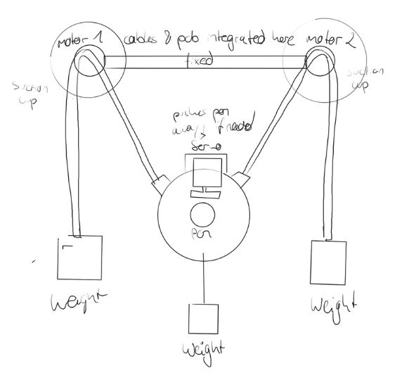 This was the
general idea behind the machine.
This was the
general idea behind the machine.
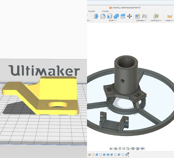 I started with
printing the stepper motor
brackets and
the
gondola.
I started with
printing the stepper motor
brackets and
the
gondola.
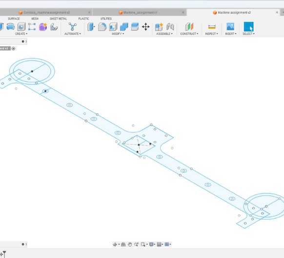 Then I designed
the wooden part to connect and hold all of the
components. It includes mounting holes for the Arduino UNO, the stepper motor
brackets,
the vacuum lifters, the battery and multiple holes to wind up the cables in a clean
way.
Then I designed
the wooden part to connect and hold all of the
components. It includes mounting holes for the Arduino UNO, the stepper motor
brackets,
the vacuum lifters, the battery and multiple holes to wind up the cables in a clean
way. Fusion file
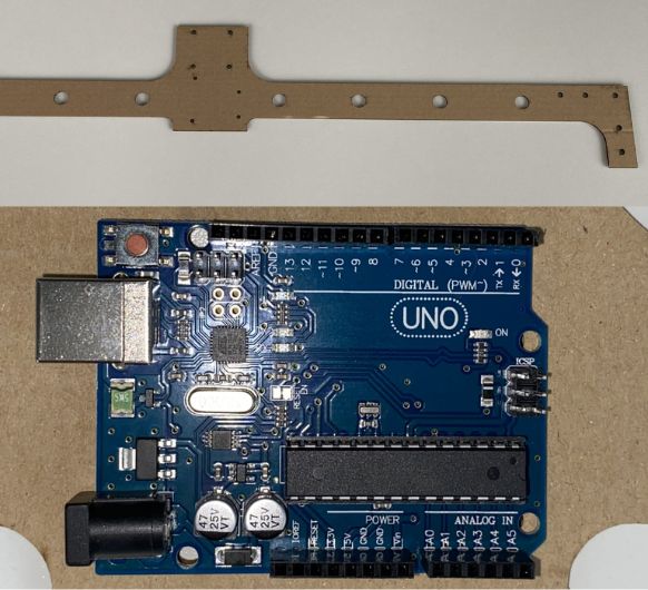 I made a test
cut with the lasercutter using cardboard to see if the
mounting holes would fit the actual components. The holes for the Arduino UNO were
off by a few millimeters. So I adjusted the design in Fusion.
I made a test
cut with the lasercutter using cardboard to see if the
mounting holes would fit the actual components. The holes for the Arduino UNO were
off by a few millimeters. So I adjusted the design in Fusion.
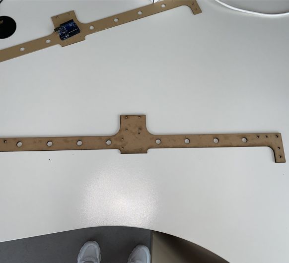 Now that
everything was fitting, I continued to lasercut the piece out of 5mm MDF.
Now that
everything was fitting, I continued to lasercut the piece out of 5mm MDF.
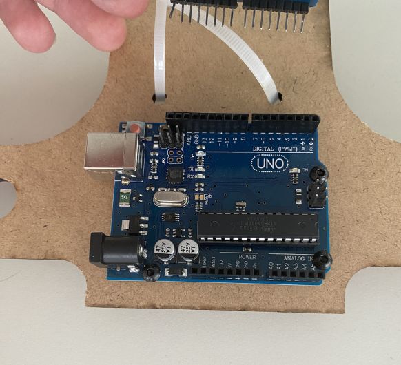 Here you can see that the Arduino aligns with the holes -> I used screws to fix the
Arduino to the holder.
Here you can see that the Arduino aligns with the holes -> I used screws to fix the
Arduino to the holder.
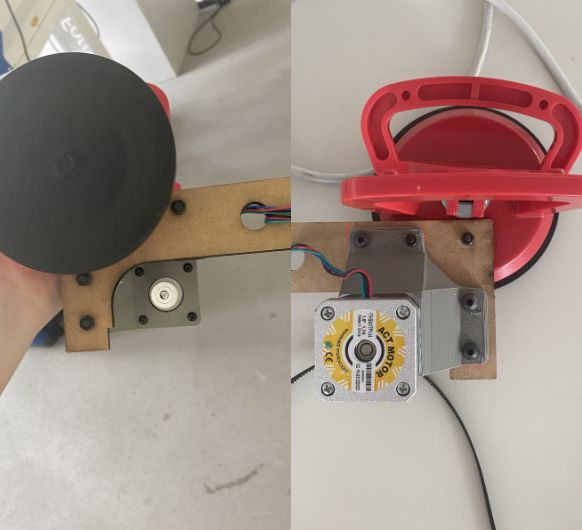 The next thing to do is mounting the motors onto the brackets and the brackets onto
the wooden holder.
The next thing to do is mounting the motors onto the brackets and the brackets onto
the wooden holder.
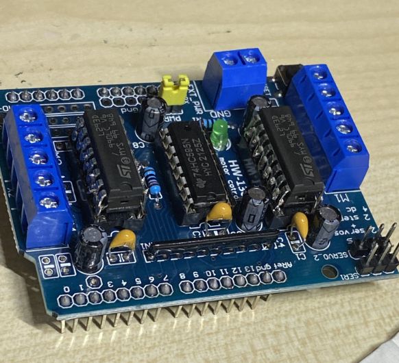
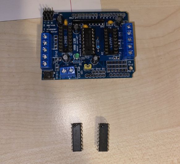 I am using the
L293D Motor Drive Shield
which plugs directly onto the Arduino. I've read that the L293D Motor Drive IC's
that are on this shield tend to overheat in this application.
I am using the
L293D Motor Drive Shield
which plugs directly onto the Arduino. I've read that the L293D Motor Drive IC's
that are on this shield tend to overheat in this application.
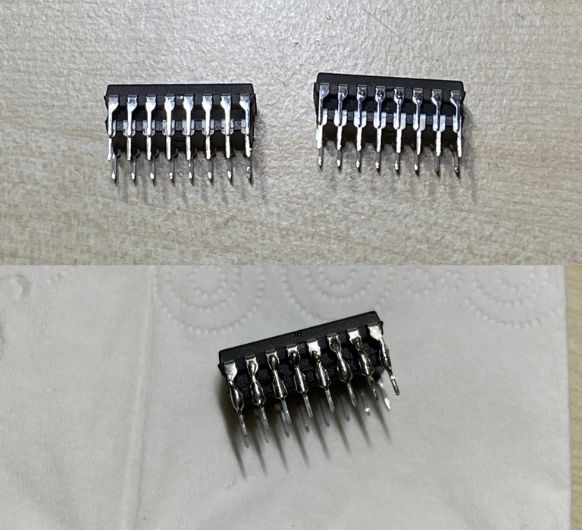 So I got two
extra IC's
to solder them ontop of the original ones.
So I got two
extra IC's
to solder them ontop of the original ones.
 This is
supposed to help with overheating since it "splits the work".
This is
supposed to help with overheating since it "splits the work".
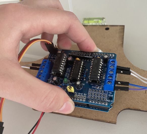 With everything
prepared
it's time to plug it onto the Arduino and connect the motors and servo etc.
With everything
prepared
it's time to plug it onto the Arduino and connect the motors and servo etc.
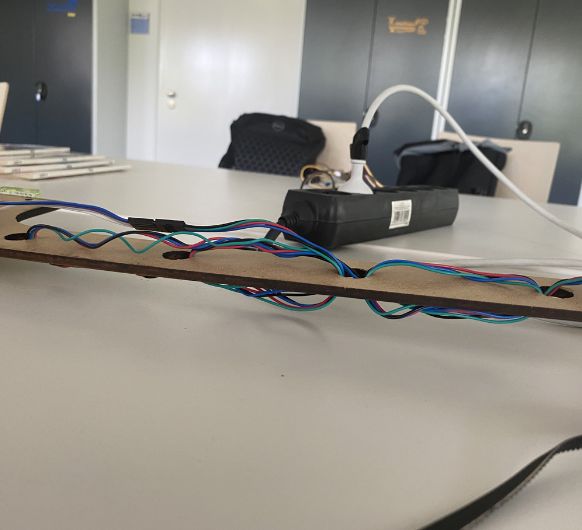 I weaved the
long cables of the
motor through the holes of the wooden holder...
I weaved the
long cables of the
motor through the holes of the wooden holder...
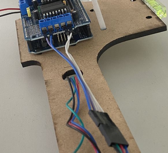 M...and
connected them to the
Motor Driver.
M...and
connected them to the
Motor Driver.
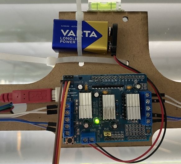
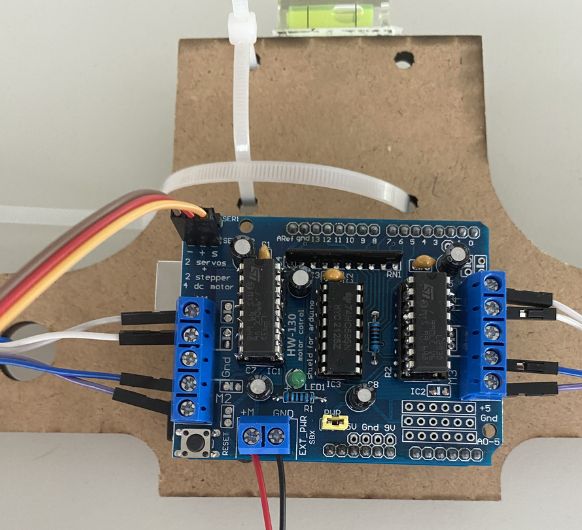 See all of the
connections here.
Left and right the motor connections, at the top the servo and at the bottom the
power supply.
See all of the
connections here.
Left and right the motor connections, at the top the servo and at the bottom the
power supply.
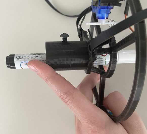 Moving to the
gondola: The pen is fixed with a screw.
Moving to the
gondola: The pen is fixed with a screw.
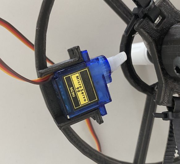 The servo is a
press fit for the holder and doesn't need any screws.
The servo is a
press fit for the holder and doesn't need any screws.
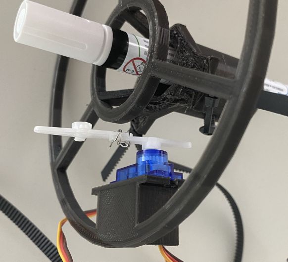 This is my
makeshift construction to elongate the rotating piece of the servo.
This is my
makeshift construction to elongate the rotating piece of the servo.
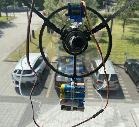
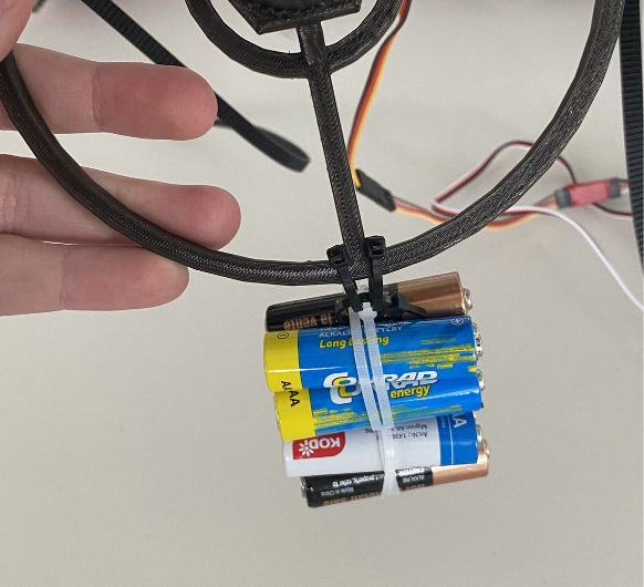 The gondola
needs some weight to it. I used a pack of AA batteries.
The gondola
needs some weight to it. I used a pack of AA batteries.
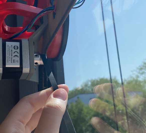
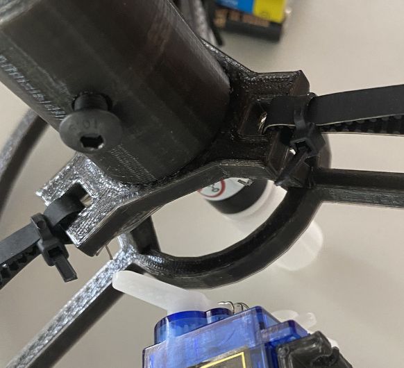 The rubber belt
is fixed to the gondola with cable ties (like everything in this project)
The rubber belt
is fixed to the gondola with cable ties (like everything in this project)
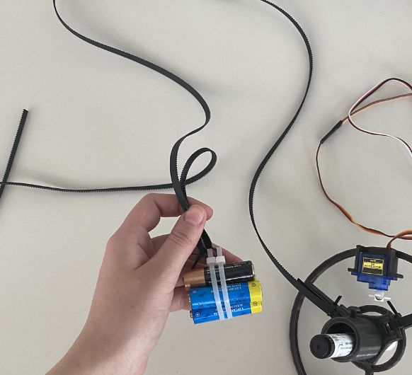 On the other
end another pack of batteries is attached as weight.
On the other
end another pack of batteries is attached as weight.
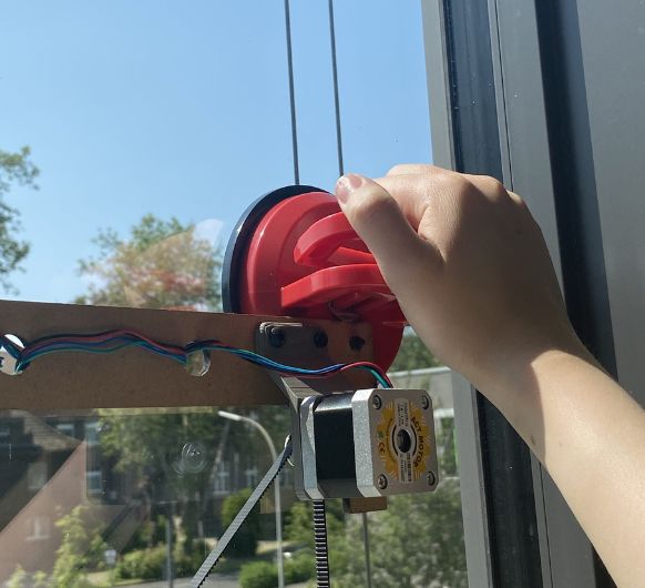 For the next
steps it's easier to have the polargraph on the window.
For the next
steps it's easier to have the polargraph on the window.
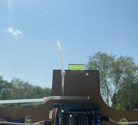 This small
add-on helped tremendously. The spirit level is very handy for putting the machine
up horizontally. Btw, the loose cable ties underneath are for holding tha battery
later on.
This small
add-on helped tremendously. The spirit level is very handy for putting the machine
up horizontally. Btw, the loose cable ties underneath are for holding tha battery
later on.
 Let's get back
to the important stuff: It's time to put the belt on the pulleys.
Let's get back
to the important stuff: It's time to put the belt on the pulleys.
 Now the gondola
will look like this. The weights help in making it steady.
Now the gondola
will look like this. The weights help in making it steady.
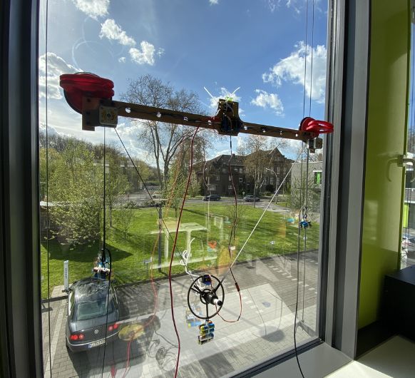
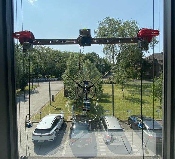 With everything
set up, the machine looks like this.
With everything
set up, the machine looks like this.
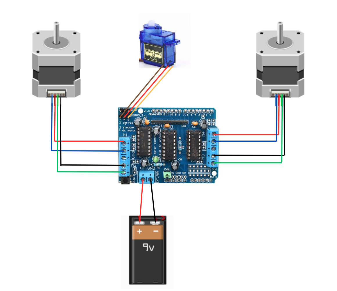 This is
the circuit for comparison.
This is
the circuit for comparison.
Programming
Please note that this section was carried out on Windows. Peculiarities of other operating systems will not be addressed.External sources used for this section: YouTube: Make Arduino XY Plotter Drawing Robot | Instructables: XY Plotter Drawing Robot | Arduino | Polargraph
Polargraph with Processing and Arduino UNO
Whats Polargraph?Polargraph is originally a particular brand of CNC plotter machines. It is often used in a generic way to describe any of these kinds of machine, but it's not the official name for machines like this.
Currently, the Polargraph brand/project is on hiatus, but it's source code is still available. The latest bundle (2017) is available on Github. It includes the polargraph-controller, which is a desktop application for controlling a polargraph machine, communicating using ASCII command language over a serial link. But we'll see what that means later.
To run the polargraph-controller, we need a certain version of Processing . Processing is a flexible software sketchbook and a language for learning how to code. (links and explanation down below) Links to the stuff you have to download: (The listed versions are important, polargraph-controller is likely to not work if you are using the wrong Processing version)
- Polargraph: Polargraph.2017-11-01
- Arduino IDE: Arduino 1.8.16 (this version works for me, other versions might also work | another version you can try if this doesn't work: Arduino 1.8.5 )
- Processing:
Processing
2.2.1
- You might need to install Java Development Kit 5.0u22 for Processing to run
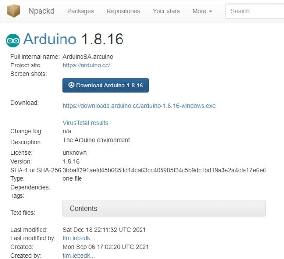 Install Arduino IDE 1.8.16
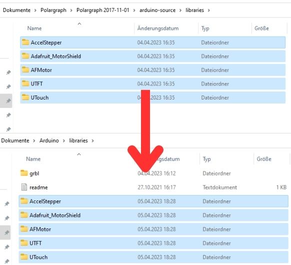 Copy the library folders out of
\Polargraph 2017-11-01\arduino-source\libraries
into your C:\Users\xxxx\Documents\Arduino\libraries
Copy the library folders out of
\Polargraph 2017-11-01\arduino-source\libraries
into your C:\Users\xxxx\Documents\Arduino\libraries
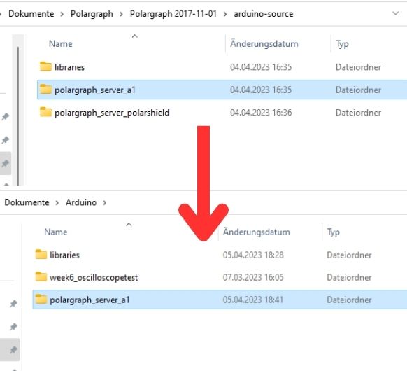 Copy \Polargraph 2017-11-01\arduino-source/polargraph_server_a1 into
your Arduino/ folder
Copy \Polargraph 2017-11-01\arduino-source/polargraph_server_a1 into
your Arduino/ folder
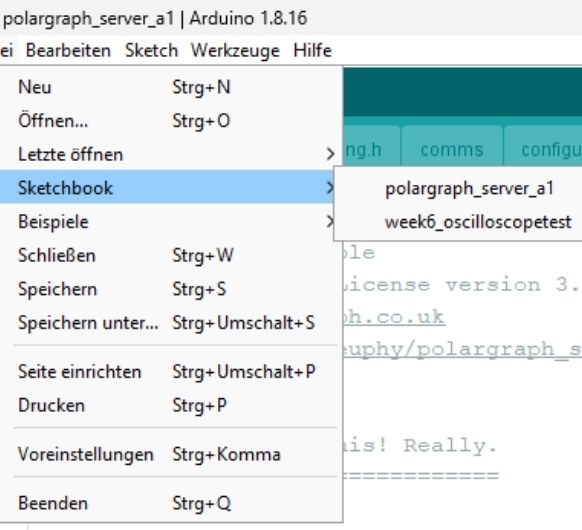 Start Arduino IDE. Open the polargraph_server_a1.ino source code in
Arduino: File->Sketchbook->polargraph_server_a1.
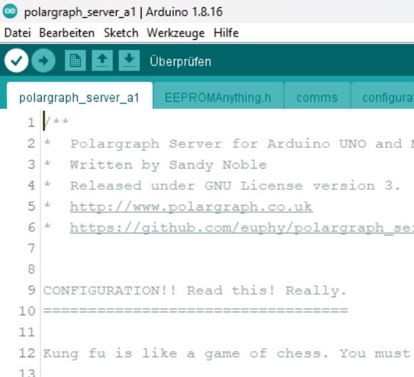
Fourteen files will open up and be displayed as tabs in the IDE. This is the source
code of the firmware.
Start Arduino IDE. Open the polargraph_server_a1.ino source code in
Arduino: File->Sketchbook->polargraph_server_a1.
Fourteen files will open up and be displayed as tabs in the IDE. This is the source
code of the firmware.
 Let it compile.
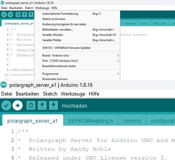 If it compiles, connect your Arduino UNO and press the "upload" button
in the toolbar to upload it to the Arduino.
If it compiles, connect your Arduino UNO and press the "upload" button
in the toolbar to upload it to the Arduino.
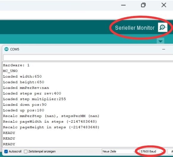 Once you do that, you should confirm that it is working properly - use
the serial monitor on the
board, set to 57600 baud to make sure that it is issuing "READY" every couple of
seconds.
Once you do that, you should confirm that it is working properly - use
the serial monitor on the
board, set to 57600 baud to make sure that it is issuing "READY" every couple of
seconds.
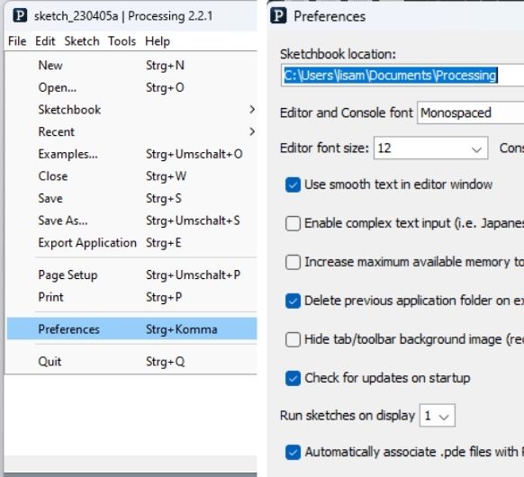 Install Processing 2.2.1.
Run Processing and find where your sketchbook folder is: (File->Preferences,
sketchbook location).
Install Processing 2.2.1.
Run Processing and find where your sketchbook folder is: (File->Preferences,
sketchbook location).
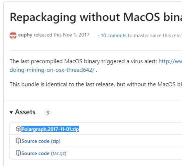 Visit the Polargraph link
above and download the ZIP file and unzip the code bundle.
Visit the Polargraph link
above and download the ZIP file and unzip the code bundle.
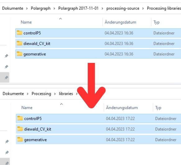 Copy the three code library folders out of
Polargraph.2017-11-01\Polargraph 2017-11-01\processing-source\Processing libraries
into your C:\Users\xxxx\Documents\Processing\libraries
Copy the three code library folders out of
Polargraph.2017-11-01\Polargraph 2017-11-01\processing-source\Processing libraries
into your C:\Users\xxxx\Documents\Processing\libraries
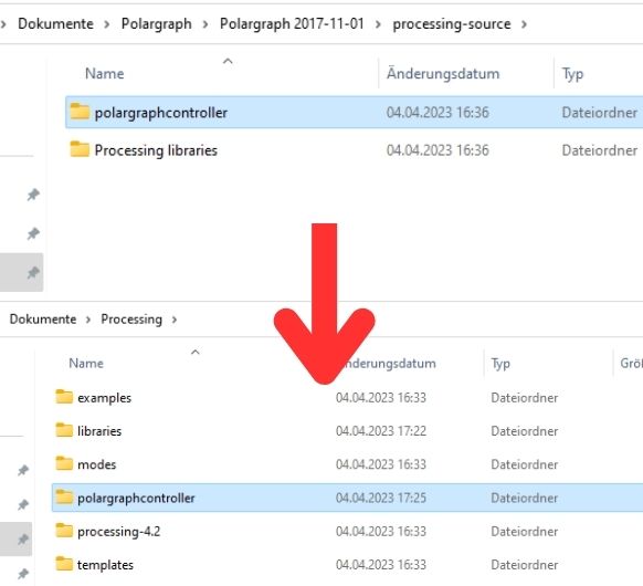 Copy the whole polargraphcontroller folder from
Polargraph.2017-11-01\Polargraph 2017-11-01\processing-source\
into your Processing sketchbook folder: C:\Users\xxxx\Documents\Processing
Copy the whole polargraphcontroller folder from
Polargraph.2017-11-01\Polargraph 2017-11-01\processing-source\
into your Processing sketchbook folder: C:\Users\xxxx\Documents\Processing
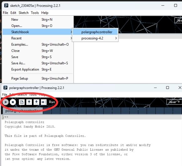 Restart Processing and go file->sketchbook->polargraphcontroller to
open the app source code.
Press the run button in the toolbar to run the sketch.
Restart Processing and go file->sketchbook->polargraphcontroller to
open the app source code.
Press the run button in the toolbar to run the sketch.
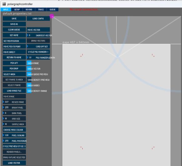 This should open.
Machine dimensions
 Supply power to your
board.
Supply power to your
board.
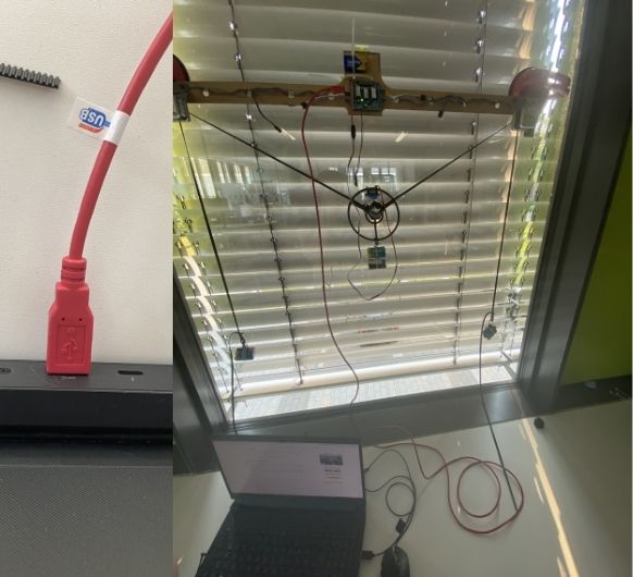 Connect your
polargraph controller.
Connect your
polargraph controller.
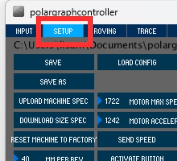 Enter the Setup section
from the tool bar.
Enter the Setup section
from the tool bar.
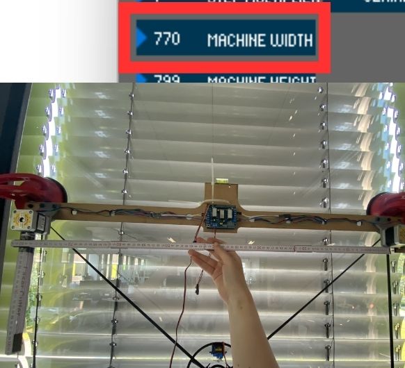 Adjust the size between
two pulleys on the Machine Width
Adjust the size between
two pulleys on the Machine Width
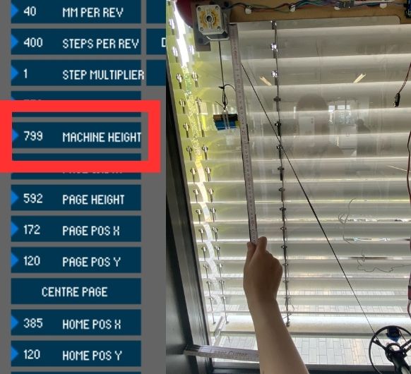 Adjust the Machine
Height (height between the pulley and the end of lowest
your machine can go with the length of it's belt)
Adjust the Machine
Height (height between the pulley and the end of lowest
your machine can go with the length of it's belt)
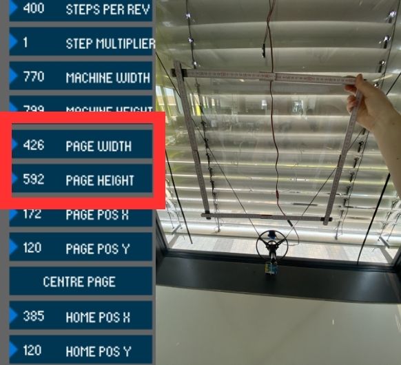 After machine
dimensions, adjust the size the area you will draw. E.g. the
area of the window you will draw on.
After machine
dimensions, adjust the size the area you will draw. E.g. the
area of the window you will draw on.
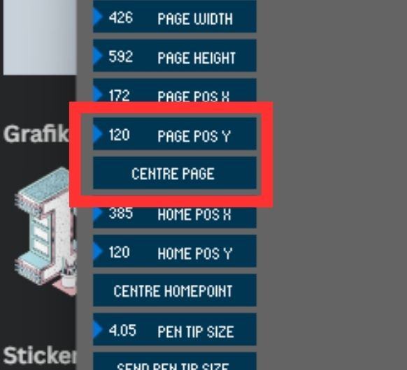 Then, first click the
Center Page button and then set the Page Pos Y value
120.
Then, first click the
Center Page button and then set the Page Pos Y value
120.
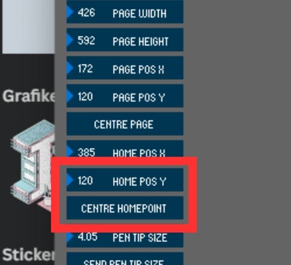 Secondly click Center
Home Point and set Home Pos Y value 120.
Secondly click Center
Home Point and set Home Pos Y value 120.
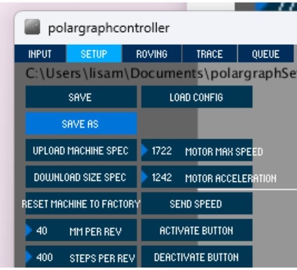
Stepper motor and pulley settings
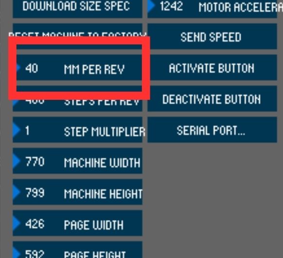 Set the MM Per Rev
value according to the pulley and belt you are using. For example, if the belt is GT2
the lue is 2mm. If the pulley has 20 teeth, 2x20 = 40mm. So, the belt will advance 40mm
each full turn.
Set the MM Per Rev
value according to the pulley and belt you are using. For example, if the belt is GT2
the lue is 2mm. If the pulley has 20 teeth, 2x20 = 40mm. So, the belt will advance 40mm
each full turn.
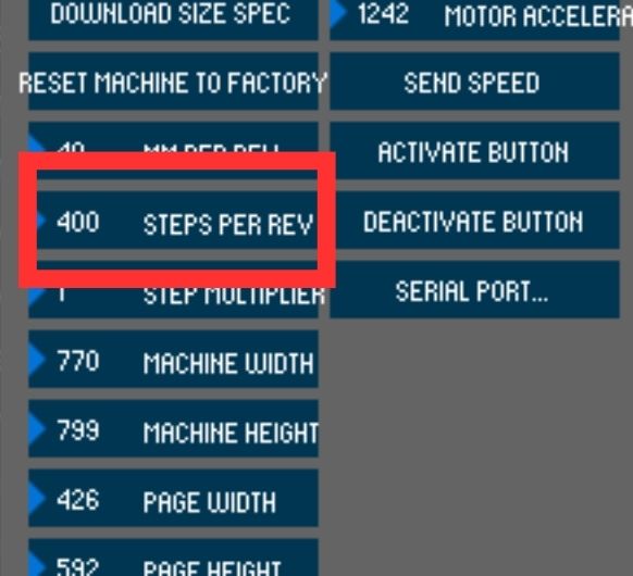 Adjust Steps Per Rev
according to the stepper motor type. For example, if te step angle of the used stepper
motor is 1.8 degrees the value is 200 steps. This value is adjust to 400 because dual
motor is used.
Adjust Steps Per Rev
according to the stepper motor type. For example, if te step angle of the used stepper
motor is 1.8 degrees the value is 200 steps. This value is adjust to 400 because dual
motor is used.
Servo settings
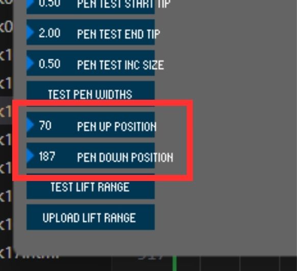 Pen Up Position and
Pen Down Position values are the operating angle of the servo motor.
Pen Up Position and
Pen Down Position values are the operating angle of the servo motor.
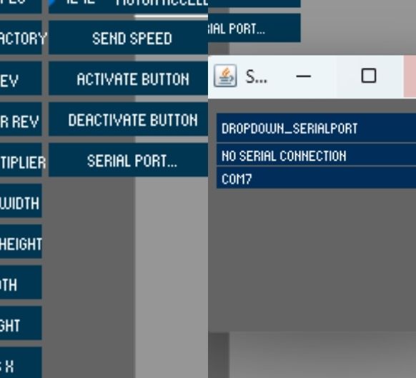 Click Serial Port and
select Arduino's port from the list of connected devices.
Click Serial Port and
select Arduino's port from the list of connected devices.
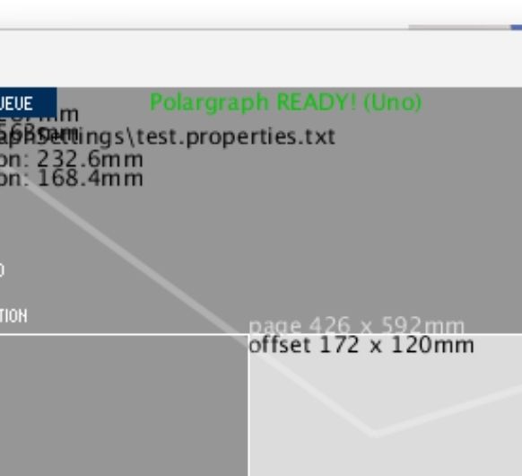 When the correct port
is selected, the 'No Serial Connection' display will turn GREEN.
When the correct port
is selected, the 'No Serial Connection' display will turn GREEN.
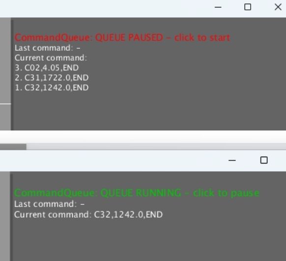 Click on 'Command
Queue' and command transmission is activated.
Click on 'Command
Queue' and command transmission is activated.
Save settings and home polargraph
 Save your setting.
Load your setting every time you turn on the program.
Save your setting.
Load your setting every time you turn on the program.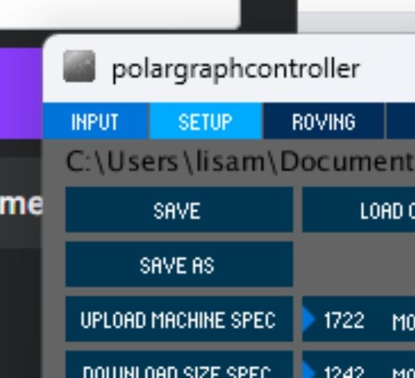 Click the Input
tab and switch to the main screen of the program.
Click the Input
tab and switch to the main screen of the program.
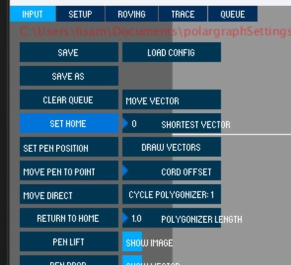 Then we will
manually set the gondola for 'Set Home' manually. Move the gondola by manually
and move it to the previously defined home point (12cm down from the center between the
2 pulleys). The gondola must be adjusted
this way before each drawing before clicking 'Set Home'.
Then we will
manually set the gondola for 'Set Home' manually. Move the gondola by manually
and move it to the previously defined home point (12cm down from the center between the
2 pulleys). The gondola must be adjusted
this way before each drawing before clicking 'Set Home'.
 After this
adjustment is done, Set Home and Set Pen Position are clicked.
After this
adjustment is done, Set Home and Set Pen Position are clicked.
 Click Set Area
to specify your drawing are. Then click Set Frame to Area to make all necessary
settings for drawing.
Click Set Area
to specify your drawing are. Then click Set Frame to Area to make all necessary
settings for drawing.
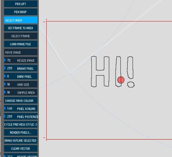
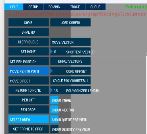 Click on Move pen to
point and click anywhere on inside the frame. The gondola should move to this point.
This is helpful in testing your settings and the connections of the motors.
Click on Move pen to
point and click anywhere on inside the frame. The gondola should move to this point.
This is helpful in testing your settings and the connections of the motors.
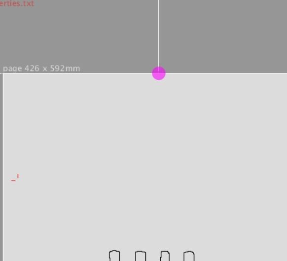
Upload an image
 Find any vector
drawing image. Convert image to the SVG format from any converter platform.
Find any vector
drawing image. Convert image to the SVG format from any converter platform.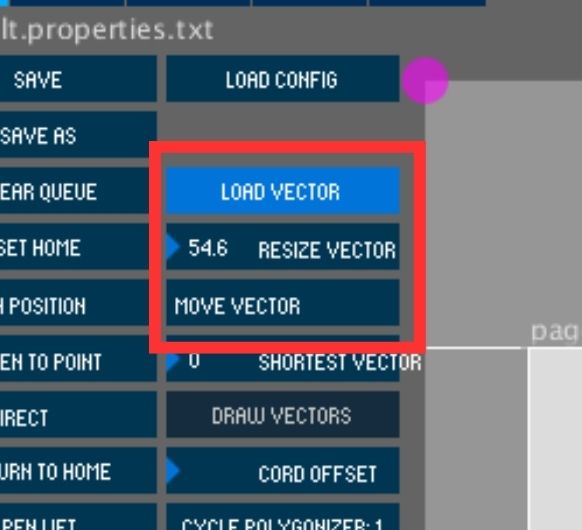 After
select Load Vector from program. Adjust image size with Resize Vector. Move
the image to the desired area with Move Vector.
After
select Load Vector from program. Adjust image size with Resize Vector. Move
the image to the desired area with Move Vector.
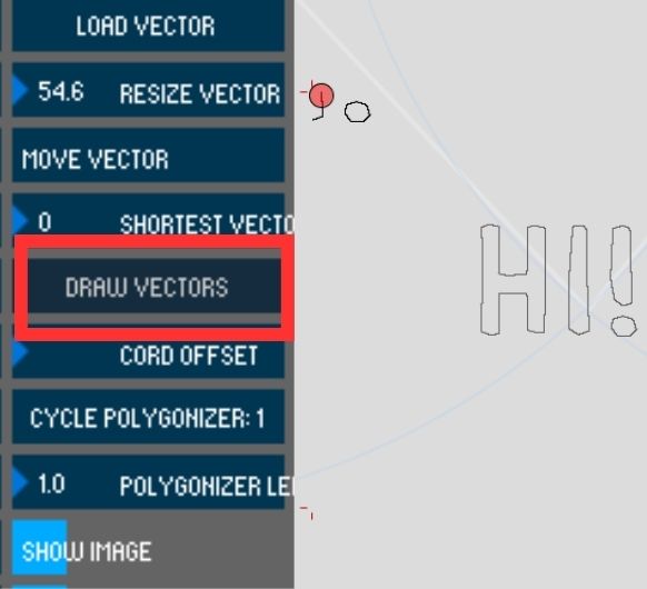 Finally, click
the Draw Vector command to start the machine.
Finally, click
the Draw Vector command to start the machine.
 While its drawing!
:D
While its drawing!
:D
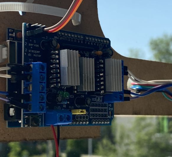 One thing to note
though is, that the machine still has a problem with overheating. Especially in hot
weather. Therefore I mounted some heatsinks, which made it a bit better. But this is definitely a part for further improvement in the future!
:D
One thing to note
though is, that the machine still has a problem with overheating. Especially in hot
weather. Therefore I mounted some heatsinks, which made it a bit better. But this is definitely a part for further improvement in the future!
:D