Final project
Plan and sketch a potential final project
- Sketched your final project idea/s.
- Described briefly what it will do and who will use it.
- At least one sketch (something visual) and one paragraph (a few senteces) of text.
Ideas:
 Idea 1: BB8 During the course called "Fundamentals of digital fabrication" I
took in my fifth semester at university, I tried building the BB-8 droid from the Star Wars
franchise.
I did not completely finish it at my first attempt, so the first idea that came to my mind for
the final project of Fab Academy was to finish the droid.
Idea 1: BB8 During the course called "Fundamentals of digital fabrication" I
took in my fifth semester at university, I tried building the BB-8 droid from the Star Wars
franchise.
I did not completely finish it at my first attempt, so the first idea that came to my mind for
the final project of Fab Academy was to finish the droid.
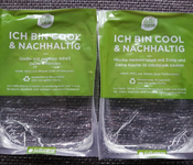
 Idea 2: Selfwatering Flowerpot I regularly order cooking boxes from Hello
Fresh. To keep the food cold and fresh, they send you ice packs with the food.
After you put the food in your fridge, you can wait for the ice packs to melt and then water
your plants with them. Since I don't want to have them lying around in my kitchen,
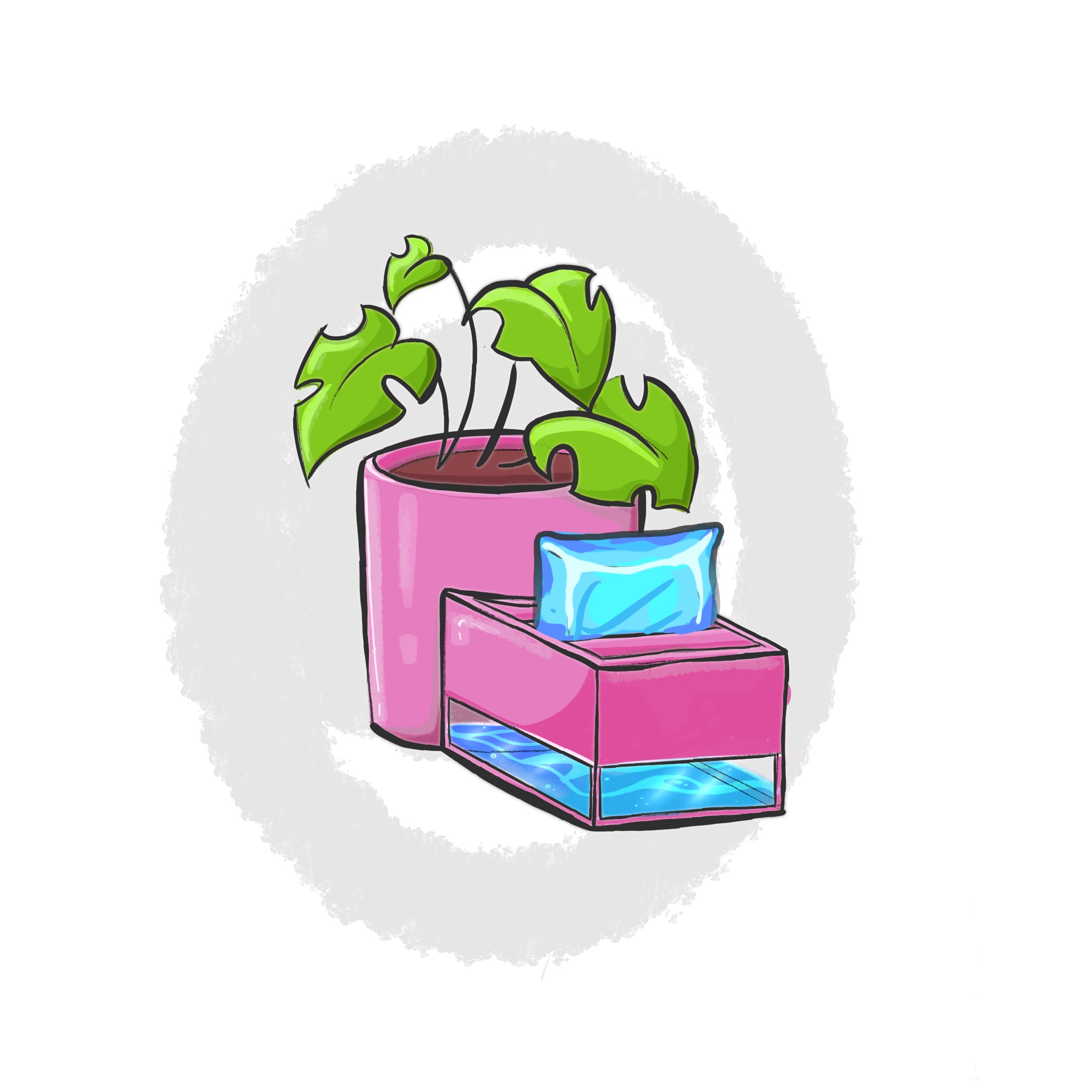
I want to build a flower pot, that has an integrated space for those ice packs. A pump will then
pump the water to the plant when needed.
Idea 2: Selfwatering Flowerpot I regularly order cooking boxes from Hello
Fresh. To keep the food cold and fresh, they send you ice packs with the food.
After you put the food in your fridge, you can wait for the ice packs to melt and then water
your plants with them. Since I don't want to have them lying around in my kitchen,
I want to build a flower pot, that has an integrated space for those ice packs. A pump will then
pump the water to the plant when needed.
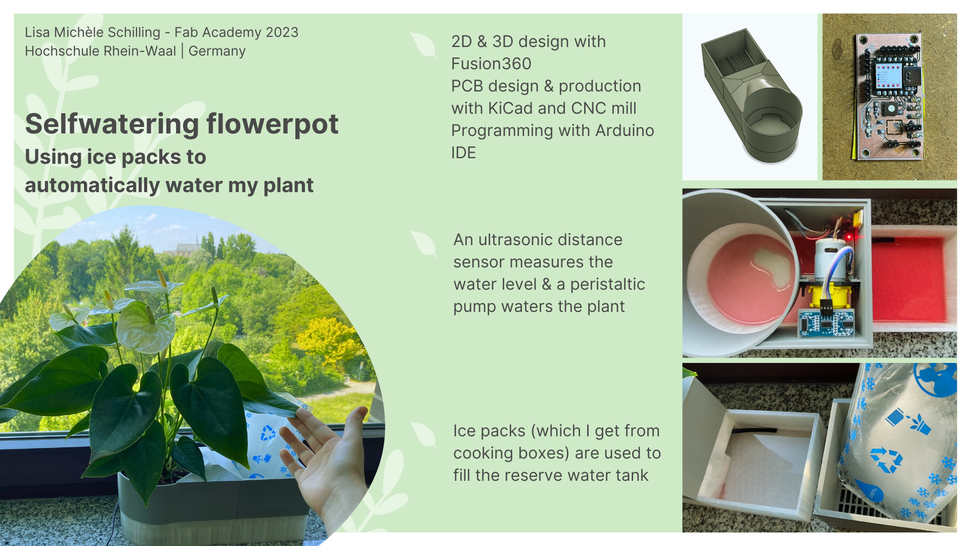
Proposed Final Project: Smart Self-Watering Flowerpot
This text was generated with the help of ChatGPT and edited by me.
 Description:
My final project is a smart self-watering flowerpot that will incorporate the various units
covered in
the FabAcademy. The flowerpot consists of two water tanks, an electronics compartment, and a
gutter
for ice pack storage. It utilizes a pump and an ultrasonic distance sensor (HC-SR04) to measure
and maintain the water level in the left tank (which the flower sits in), ensuring automatic
watering for the flower when
needed.
It is supposed to solve the problem of me having the icepacks of Hellofresh laying around in my
kitchen. I get weekly cooking boxes that come with ice to keep the groceries cold. The ice will
melt in the tank and the flower will receive the water via a pump.
1. 2D and 3D Design:
The flowerpot's design will involve both 2D and 3D elements. The overall structure, including the water tanks, gutter, and electronics compartment, will be designed in 3D to ensure proper fit and functionality. The 2D design will include creating schematics and diagrams for the electronic connections and layout.
2. Additive and Subtractive Fabrication Processes:
To construct the flowerpot I will mostly use additive fabrication processes. Additive processes such as 3D printing can be used to create the main structure and components, including the water tanks, gutter, and electronics compartment. Subtractive processes may involve cutting or drilling holes for the pump, sensor, and other electronic components. But I will mainly use subtrative processes such as lasercutting to add small decorations to the project.
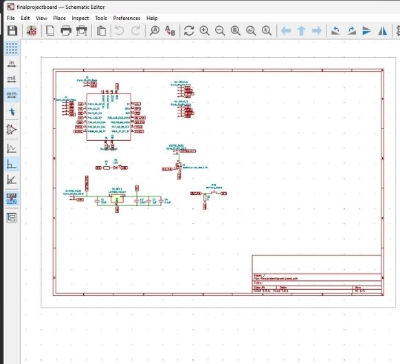
3. Electronics Design and Production:
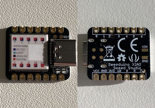
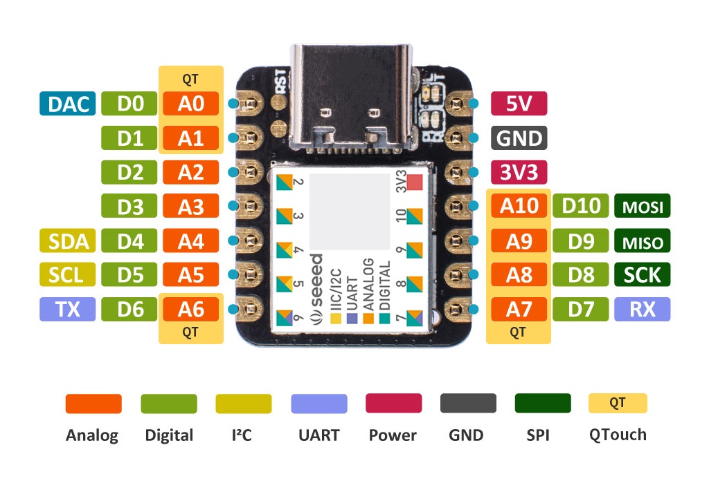
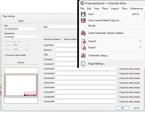
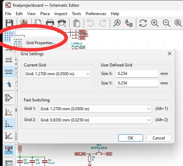
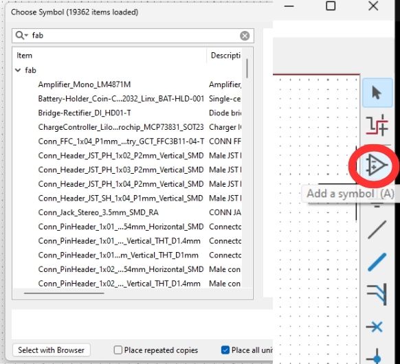
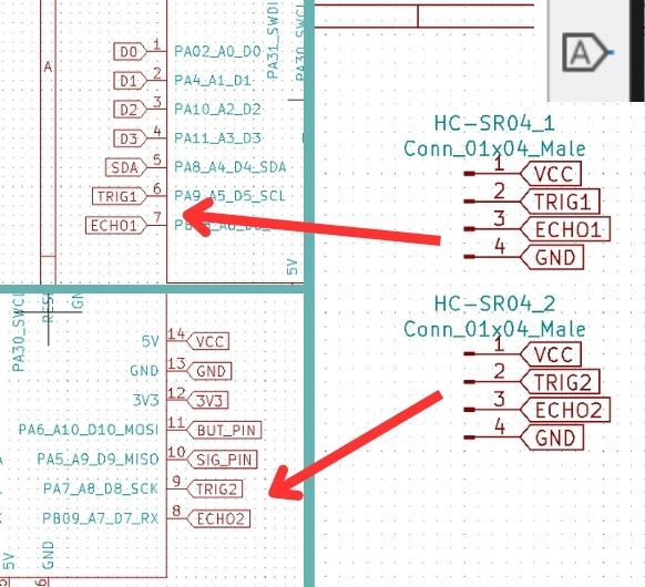
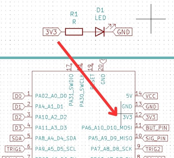
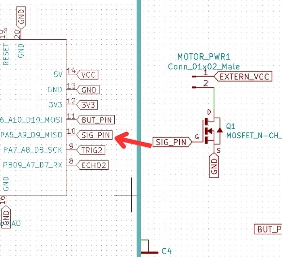
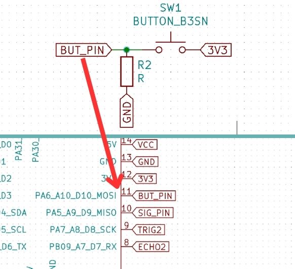
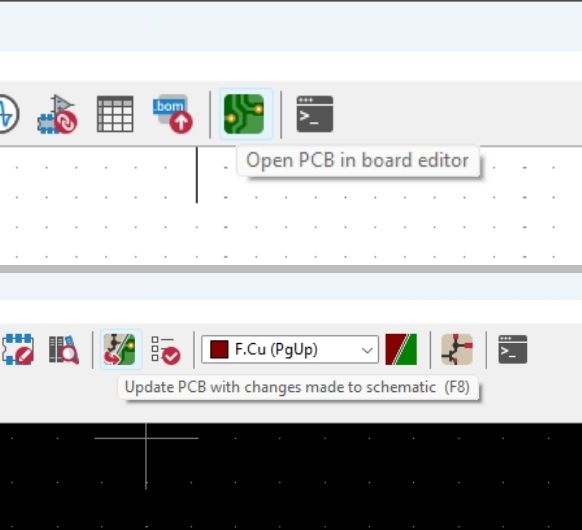
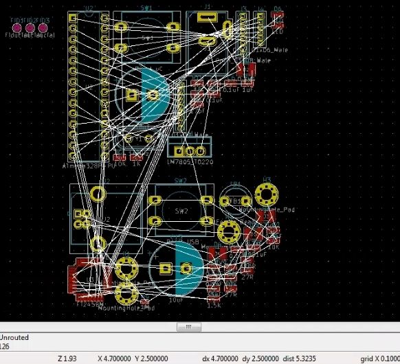
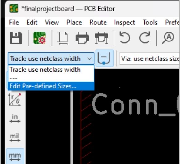
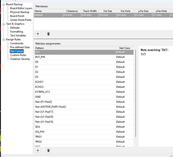
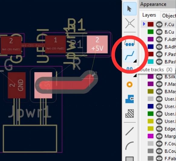
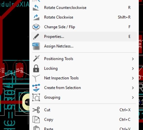
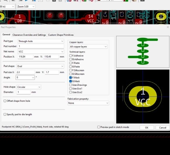
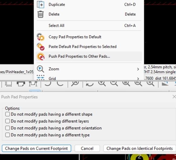
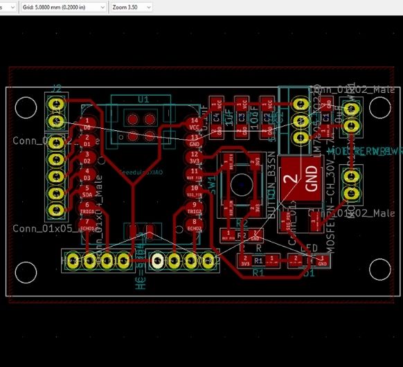
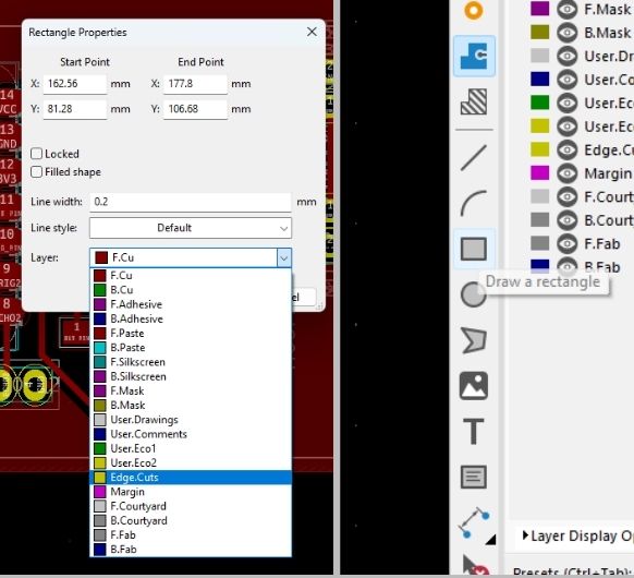
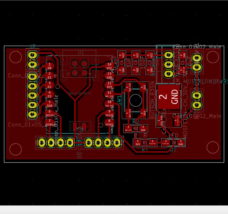
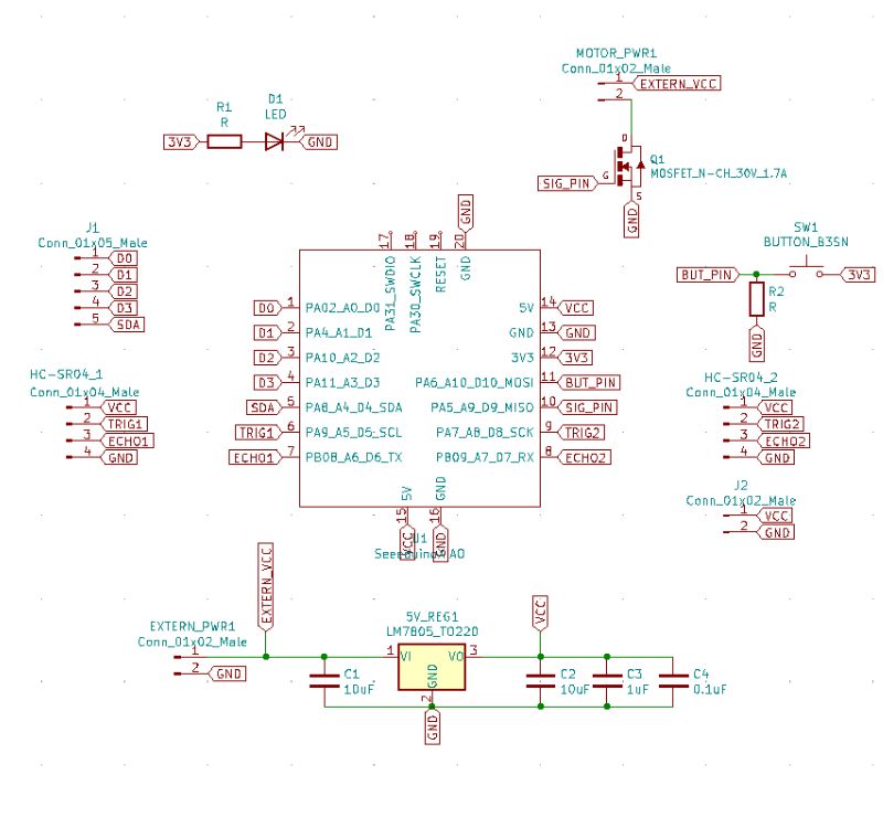
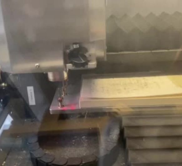
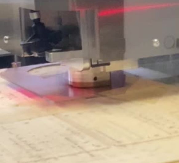
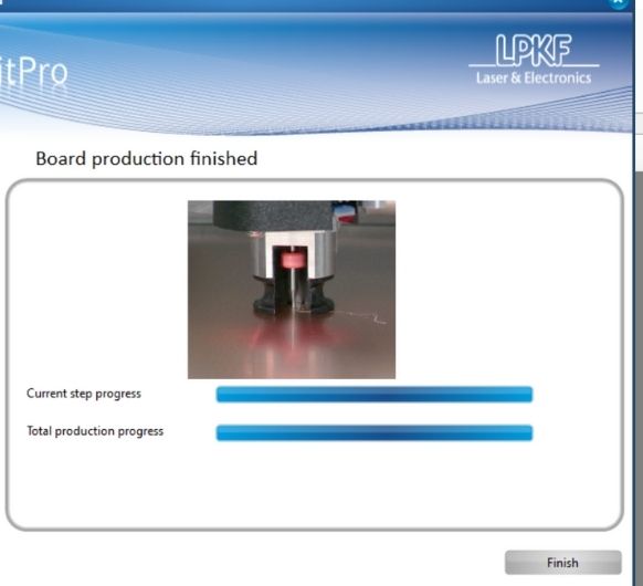
The project will require designing the electronics system to control the water level and automate the watering process. This includes selecting and integrating connections for the components such as the XIAO SAMD21, pump, ultrasonic distance sensor, and any other necessary electronic components (5V regulator, MOSFET etc). Circuit design and PCB layout will be created in KiCad, and the PCB can be fabricated using the CNC in the Lab.
4. Embedded Microcontroller Interfacing and Programming:
The heart of the project will be this previously described embedded microcontroller responsible for controlling the water level and pump activation. The microcontroller will interface with the ultrasonic distance sensor to measure the water level in the left tank. Programming the microcontroller will involve writing code to read sensor data, control the pump, and implement the self-watering logic.
5. System Integration and Packaging:
Once all the individual components are designed, fabricated, and programmed, the system integration phase begins. This involves assembling the 3D-printed parts, mounting the electronics components inside the electronics compartment, and connecting all the necessary wires and tubes for proper functionality. The final packaging will ensure a neat and organized flowerpot design.
Bill of Materials (BOM):
- 3D-Printed Components:
- Main structure (flowerpot body, water tanks, gutter)
- Electronics compartment enclosure
- Electronics Components:
- PCB components (copper plate, pin headers, Resistors, capacitors, and other electronic components as required)
- Ultrasonic distance sensor (HC-SR04)
- Water pump
- Wires and connectors
- 12V DC power supply
- Fasteners and Mounting Hardware:
- Screws, nuts, bolts for assembling components
- Ice Packs (for water supply):
- Ice packs or similar frozen water containers to melt and provide water for the right tank -> in my case, supplied by my weekly HelloFresh cooking boxes.
- Miscellaneous:
- Tools for fabrication (3D printer, cutting tools, drilling tools)
- Soldering iron and solder (if applicable)
- Computer and cables for programming and testing
Final Project Q&A
- What will it do?
The smart self-watering flowerpot will automatically monitor the water level in the left tank and provide water to the flower whenever the water level is low. It achieves this by using an ultrasonic distance sensor (HC-SR04) to measure the water level and a pump to transfer water from the right tank (from HelloFreshs' melted ice packs) to the left tank. The system will be designed to ensure optimal watering for the flower, maintaining an adequate water level.
- Who has done what beforehand?Similar self-watering systems and automated flowerpots exist in the market. Various DIY projects
and commercial products have implemented similar concepts using different techniques and
components. Some projects may have used sensors like HC-SR04 for water level measurement, while
others might have used different types of sensors and control mechanisms.
Antoher project I came across is the Smart
Planter
from Svetlana Shishkovets. Her project includes a lot of features and extras such as growth
light, a desktop app and a waterlevel indiator. It is a very cool project and I read her final
project page for some inspiration.
In comparison to her project, I want mine to be smaller, as it should fit my windowsill.
In general, my final project is very much tailored to my needs and is supposed to solve one of
my own
problems and it's not looking to solve a general problem a lot of people might have or not have.
It is a
specific use case that only uses the minimum of components to achieve it's task. This approach
made
it possible for me to spend time on the integrating and packaging aspect of the project.
The design will include:
- 3D design for the flowerpot structure, including the main body, water tanks, gutter, and electronics compartment.
- Electronics system design, including the selection and integration of components such as the microcontroller, ultrasonic distance sensor, pump, and necessary supporting circuitry.
- Embedded system programming for the microcontroller to monitor the water level and control the pump.
The materials and components required will include:
- 3D-printed parts for the flowerpot structure.
- Electronics components such as a ultrasonic distance sensor (HC-SR04), water pump, wires, connectors, tubing, resistors, capacitors, and potentially a PCB board for electronics integration.
- Power supply (DC power supply or battery pack).
- Fasteners and mounting hardware.
- Ice packs or similar frozen water containers.
The 3D-printed parts can be created using a 3D printer. Electronics components such as the PCB will be self-made and other components can be sourced from local electronics stores, online retailers, or specialized suppliers. Power supplies, fasteners, and other miscellaneous items can be obtained from hardware stores or online suppliers. Ice packs will be provided through my weekls orders of HelloFresh.
- How much will they cost?The cost will vary depending on factors such as the quality of components, the quantity required, and the availability of materials. The follwing is an estimate that includes expenses for 3D printing, electronics components, power supply, fasteners, and miscellaneous items:
| Component | Price (€) | Source |
|---|---|---|
| Peristaltic Pump | 5 | FabLab |
| HC-SR04 | 3.80 | FabLab |
| Filament | 25 | FabLab |
| PCB Plate and Components | 10 | FabLab |
| Test Plant | 11.90 | Self-bought |
| Ice Packs | 0 | Self-bought |
| Wires, Screws, etc. | 8 | FabLab + Self-bought |
| Total Cost | 63.7 | |
| Self-bought Cost | 15.9 |
The parts and systems that will be made include:
- 3D-printed flowerpot structure, including the main body, water tanks, gutter, and electronics compartment.
- Electronics system with the microcontroller, ultrasonic distance sensor, water pump, and associated circuitry.
- Embedded system programming for the microcontroller to control the watering process.
The processes involved in the project include:
- 2D and 3D design + printing for the flowerpot structure.
- Electronics design and PCB production.
- Embedded system programming for the microcontroller.
- Assembly and integration of all components.
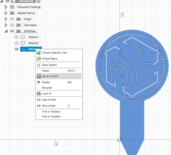
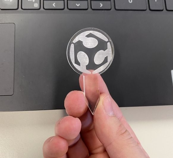
- Lasercutting/ -engraving for decoration purposes.
- Testing and troubleshooting to ensure proper functionality.
- How accurate and reliable is the ultrasonic distance sensor (HC-SR04) for water level measurement? Are there any alternative sensors that can be considered?
- What is the optimal pumping mechanism and flow rate to ensure efficient watering without damaging the flower?
- How will the system handle situations such as power outages or low battery conditions?
- Are there any safety considerations or measures to prevent overwatering or potential water leakage?
- How will the system handle maintenance?
The HC-SR04 has an inaccuracy of about +/- 6mm. I included this inaccuracy in my code so that it doesn't affect the functionality. Other than that it has worked very reliable so far. I also could have used float level sensors or soil moisture sensors. I still chose the HC-SR04, because it allowed me to have a nicely integrated product that has no sensors sticking out of the electronics compartment. I also read, that the other sensor erode quite quickly. And for the float level sensor I would have maybe had to work with seals. WHich I didn't want.
I chose a plant that comes in a plastic pot that has a string attached to it at the bottom. The plant is therefore slightly elevated and the soil sucks up water by itself whenever needed.
Power outages are not a problem. The power supply is a 12V power adapter. Nothing gets lost with the loss of power. As soon as power is supplied again, the mechanism will start to work again.
This is the biggest problem of the construction. It's far from safe regarding the risk of electronics coming in contact with water. You have to bevery careful when using it. The roof of the electronics compartment is beveled so water can flow away. But it is still very much possiblefor water to get inside. Especially from the bottom. This is the topic of further improvement ofthe project.
All components can be unscrewed and all the 3D printed parts can be deassembled. You can reprogram the PCB withoutremoving it from the electronics compartment.
- Program Functionality: Test the program that controls the water level monitoring and pumping mechanism. Verify that the program effectively detects low water levels in the left tank and activates the pump to water the flower. Ensure that the program runs without errors and performs the desired actions reliably.
- 3D Print Quality: Inspect the 3D-printed parts of the flowerpot structure, including the main body, water tanks, gutter, and electronics compartment. Evaluate the overall quality of the prints, considering factors such as surface finish, dimensional accuracy, structural integrity, and visual appeal. Ensure that the 3D-printed parts fit together properly and provide adequate support for the components.
- Water Pumping: Verify that the water pump operates correctly and delivers water from the right tank (melted ice packs) to the left tank when needed. Observe the pumping mechanism to ensure it functions smoothly without any leaks or blockages. Confirm that the pump delivers an adequate amount of water to effectively water the flower.
- Watering Effectiveness: Monitor the flower's hydration level and health after using the self-watering system. Assess whether the flower receives sufficient water to maintain its health and growth. Observe any improvements in the flower's vitality compared to manual watering or traditional methods.
- Overall Aesthetics: Evaluate the visual appeal and overall aesthetics of the smart self-watering flowerpot. Consider factors such as the design coherence, color choices, and integration of the electronic components. Ensure that the flowerpot's appearance and size is visually pleasing and enhances the overall presentation.

3D design:
 I decided to pursue idea 2 "Selfwatering flowerpot" first. For this week I will design
the
flowerpot in Fusion360.
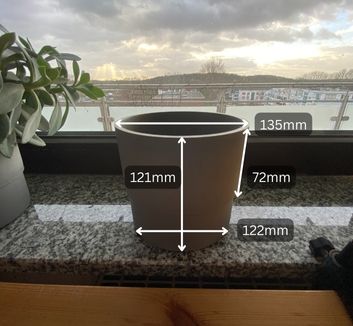
To start off, I need to measure the dimensions of one of my other flowerpots, since I
want the
selfwatering one to fit in with the rest.
I decided to pursue idea 2 "Selfwatering flowerpot" first. For this week I will design
the
flowerpot in Fusion360.
To start off, I need to measure the dimensions of one of my other flowerpots, since I
want the
selfwatering one to fit in with the rest.
 Now over to Fusion:
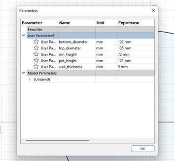
Sincen I don't know if I'll make changes to the model in the following weeks, I am using
paramaters for all of the dimensions.
Like this, I can change the value of any parameter here in this very same window and the
changes
will be applied everywhere automatically.
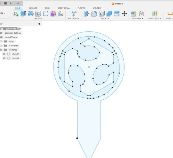
Process:
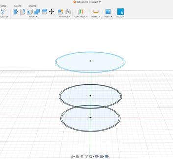
1. Use offset construction planes for sketches at different heights.
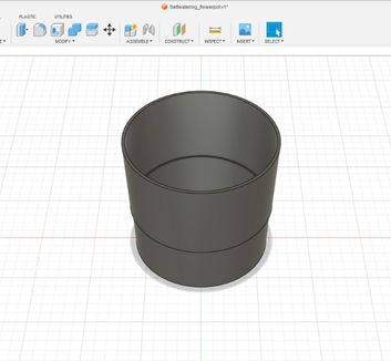
2. Extrude bottom and Loft between the different faces for an evenly interpolated volume.
3. Create new sketch for the watertank. Project the ground-sketch into this sketch and use constraints to fix the watertank to the border of the flowerpot.
Before I can go on with the design, I need to think about the electronic components I will be using. This is crucial since I need to know how much space they will occupy.
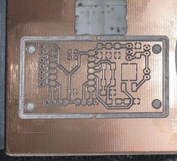
Components and their dimensions (LxWxH):- Selfmade PCB: 6 x 3.2 x 0,2cm
- (Waterpump) Kamoer NKP-DC-S10Y: 6.75 x 5.45 x 4.03cm
- 1x (Ultrasonic distance sensor) HC-SR04: 4.5 x 2.1 x 1.8cm
I looked for holders of these components on different forums and websites, but I would have needed to edit them anyway, so I figured it would make more sense and even save some time to just design them myself from scratch.
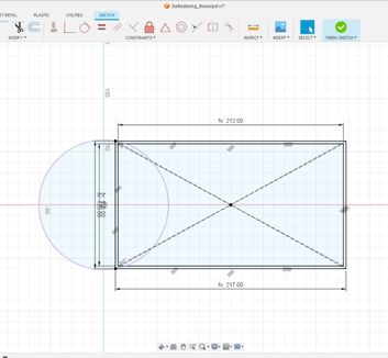
Starting with the HC-SR04 holder:
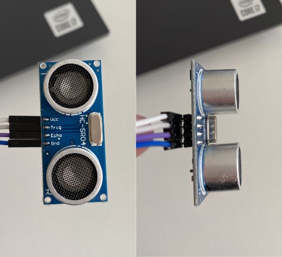
This is the sensor, I took measurements myself to create the holder for it.
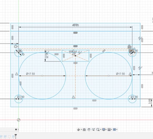
Here it is sketched out. I added half a millimeter to the dimensions that needed to fit parts f the HC-SR04 such as the holes for the emitter and receiver etc. This was important, because our 3D printers aren't that accurate (as I learned in the 3d printing assignment ). It's similar to the Kerf of a lasercutter, just that here, the holes usually end up being smaller (instead of bigger). The material gets squeezed out by the nozzle and makes to holes about 0.5mm smaller than they are in the design file. You can download the Fusion file to have a closer look at the dimensions, or get them from the datasheet.
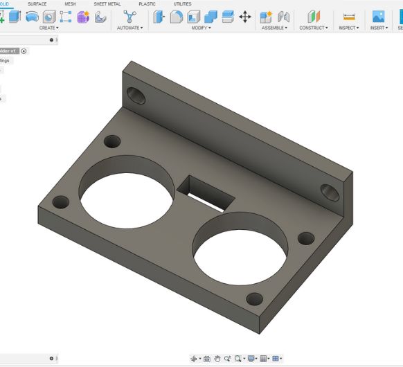
I extruded the sketch and added holes on the vertical wall, just in case I need them later on to mount the holder.
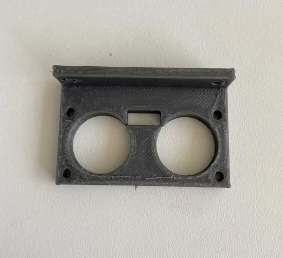
To test if the HC-SR04 would actually fit in this holder, I made a test print with the Ultimakers.
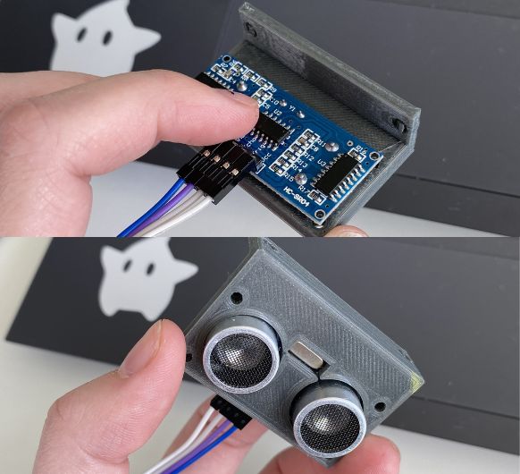
Fits perfectly. You can see the bit of room that I left. It even has some extra space, but this is optimal. This holder doesn't need to be a super snug fit!
Now going on with the pump holder:
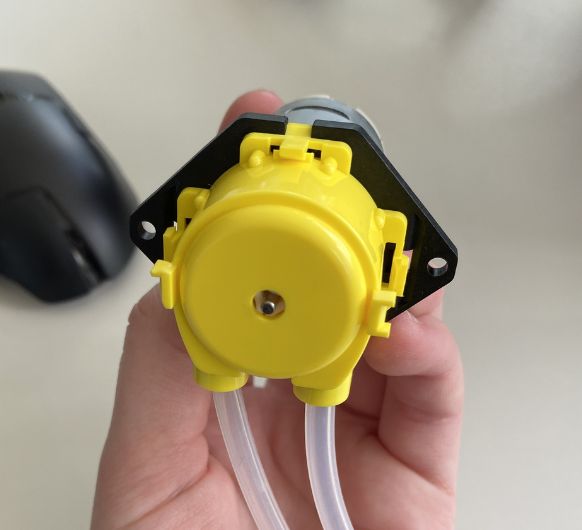
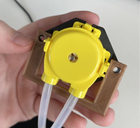
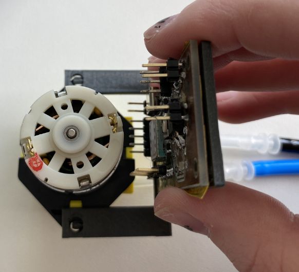
Here we have the pump, I inted to fixate it with the two holes it has on each side.
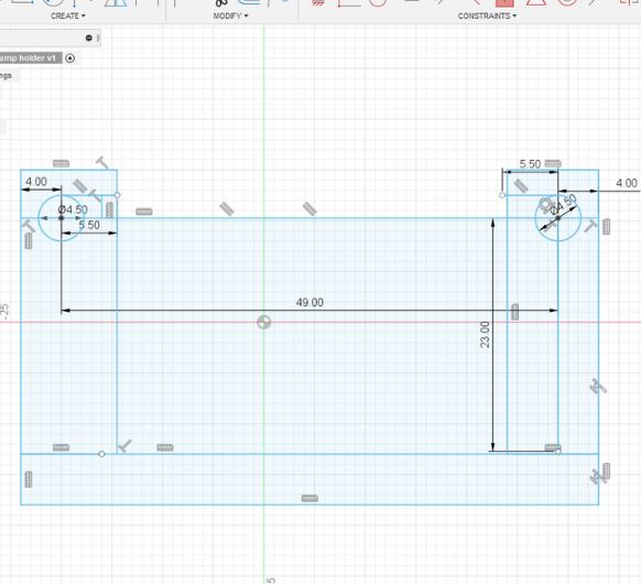
I took the needed measurements and sketched it out.
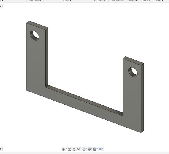
The extruded sketch.
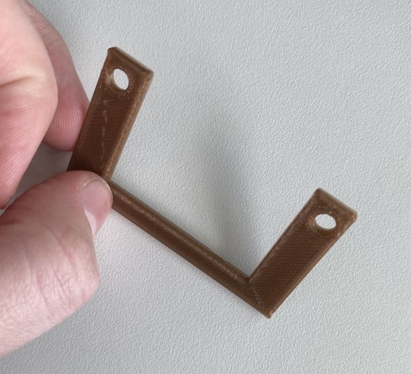
To test if the pump would actually fit in this holder, I made a test print for it as well.
The first one wasn't optimal, so I made the holes a few millimeters closer together in Fusion.
Second try et voilá.
Two down one to go: PCB holder
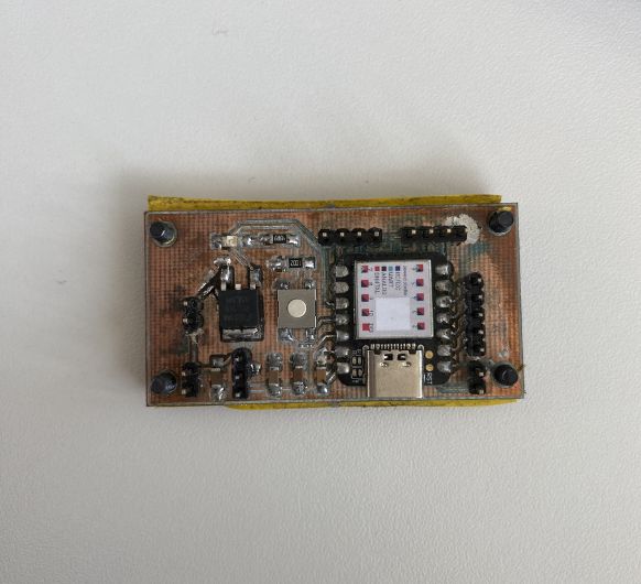
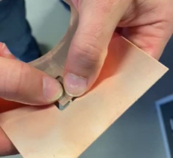
This is my PCB.
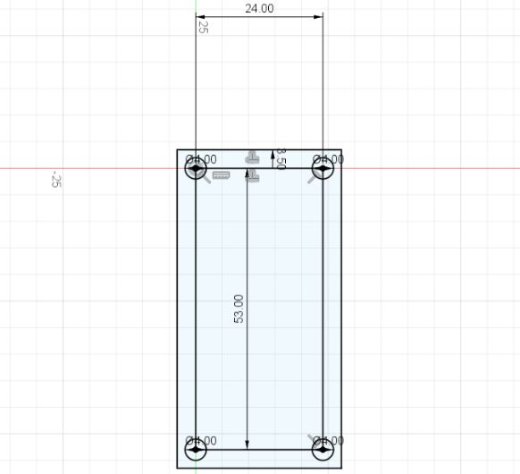
I took the dimensions and sketched it in Fusion.
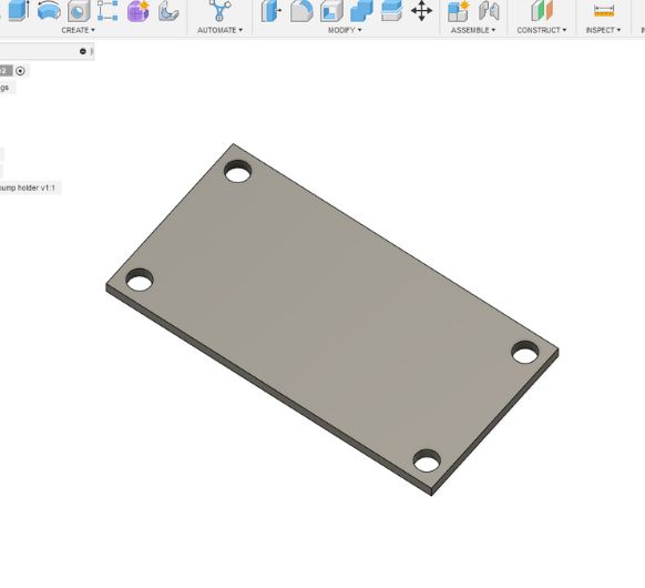
I extruded the sketch.
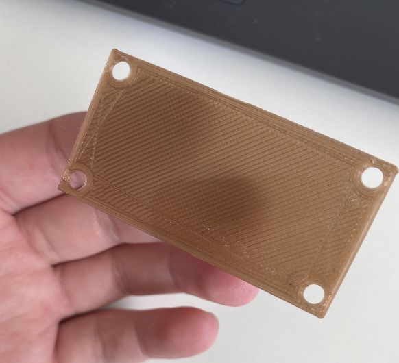
And the test print.
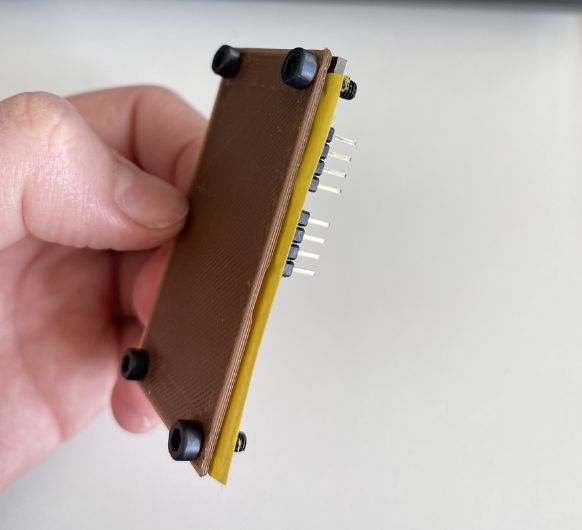
Fits very well!
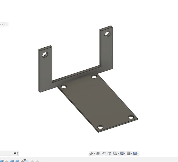
To make a compact design that can fit all my electronics into the electronics compartment, I decided to join the pump holder and the pcb holder.
This test print shows me, that having the PCB holder in the middle would make to connections of some cables very hard.
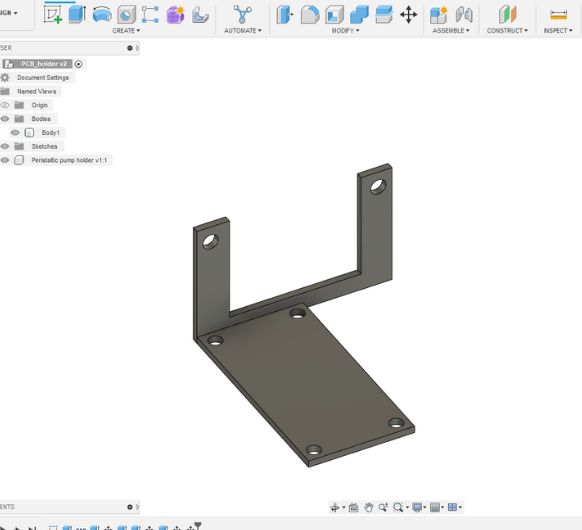
So in Fusion I moved it to the left. I didn't make another test print for this, because I already could tell from all of my previous test that the dimensions were right.
Designing the pot:
Create new sketch for the watertank. Project the ground-sketch into this sketch and use constraints to fix the watertank to the border of the flowerpot.
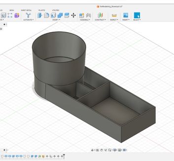
Now with the dimension of my components in mind, I design and extrude the watertank
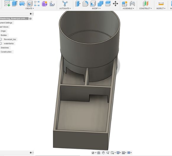
Added tunnels to connect each watertank with it's respective part of the electronics compartment.
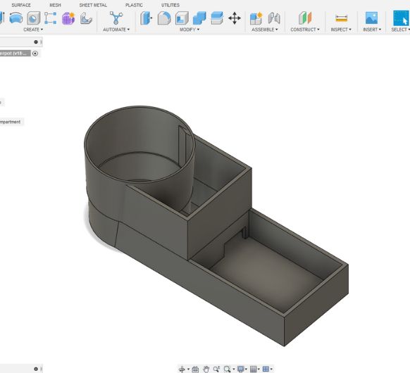
Extruded the electronics compartment.
As well as the gutter--part.
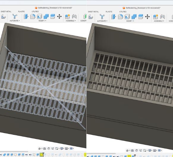
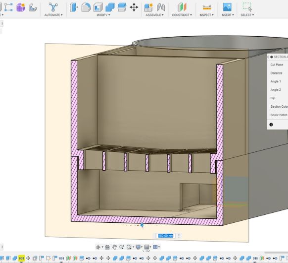
I then sketched the actual gutter part and extruded it.
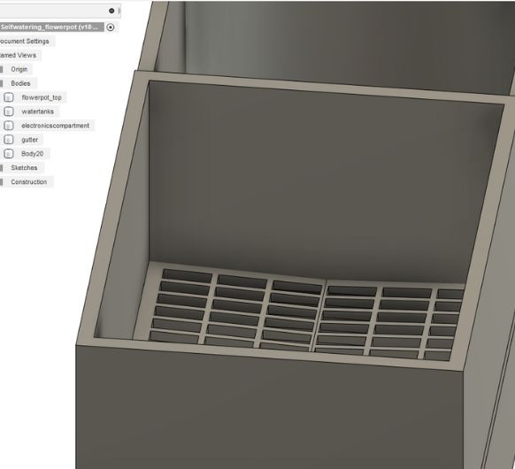
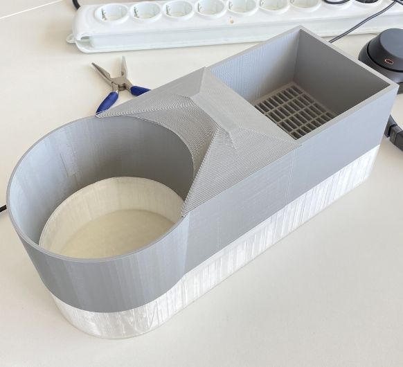
Slight bevel added so that the water can flow downwards.
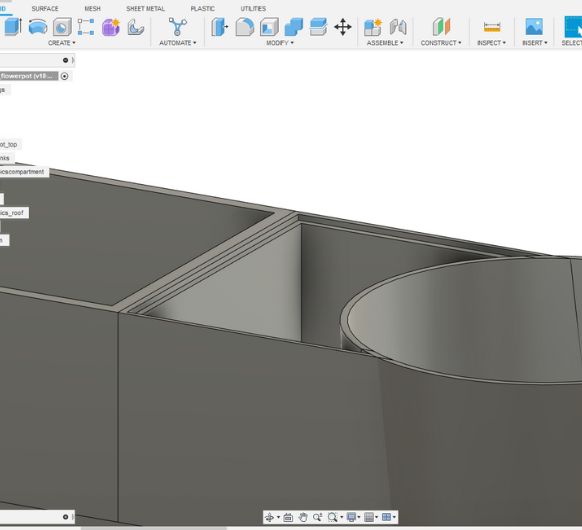
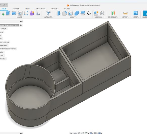
Here I added the part on which the roof will lay on.
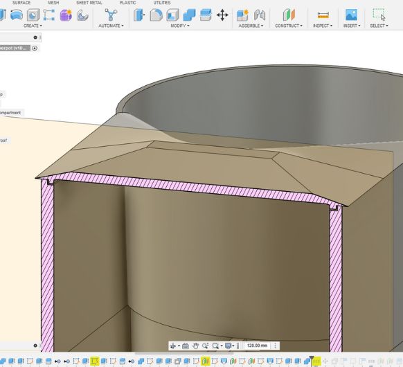
The roof itself is modeled by using Loft between two sketches I drew. Here you can see a section analysis of the roof laying ontop of the electronics compartment.
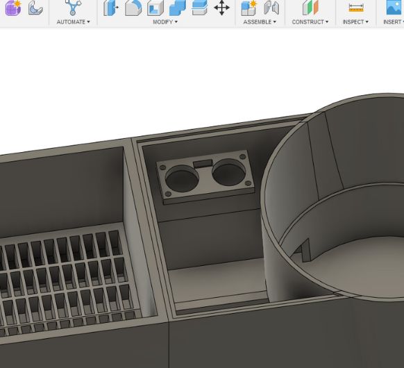
Now I am inserting the previously modeled component holders. First off, the HC-SR04. It's placed over the water tank part that is connected to the plant. It senses whne the plant has now water left.
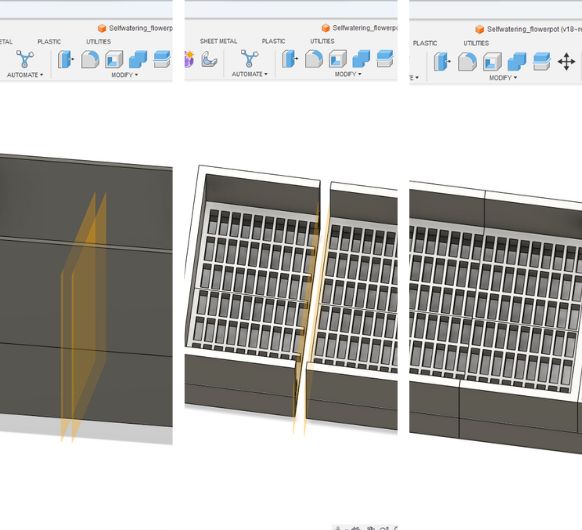
The gutter was a bit too big for the Ultimaker S5. I used construction planes to spit the body and remove some centimeters.
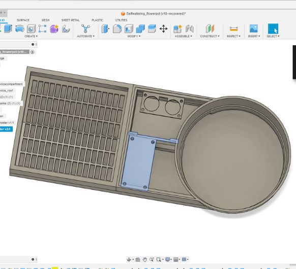
I also added the PCB/pump holder.
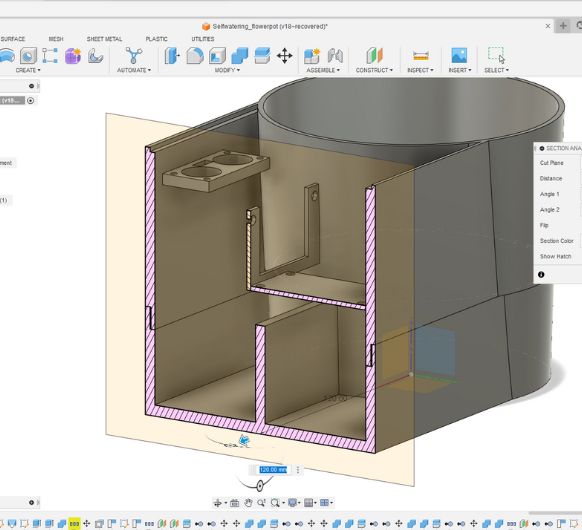
Here you can see that I lowered a part of the wall of the watertank so that I can stack the electronics compartment on top of it.
Same thing for the gutter. This ensures easy removeabilty and a stable and snug fit.
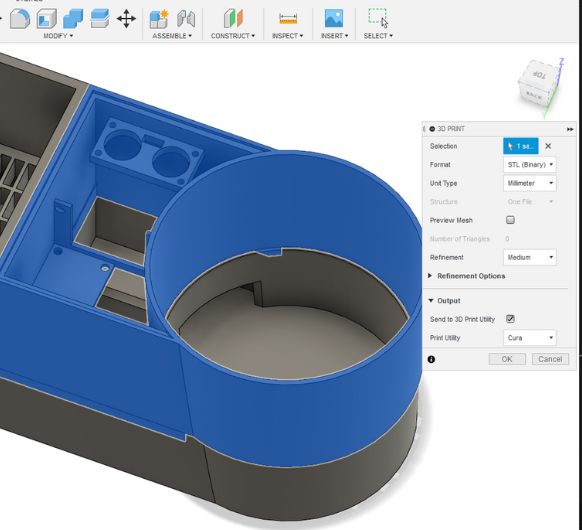
I'm using Fusion 3D print option to send the different bodies directly to Cura.
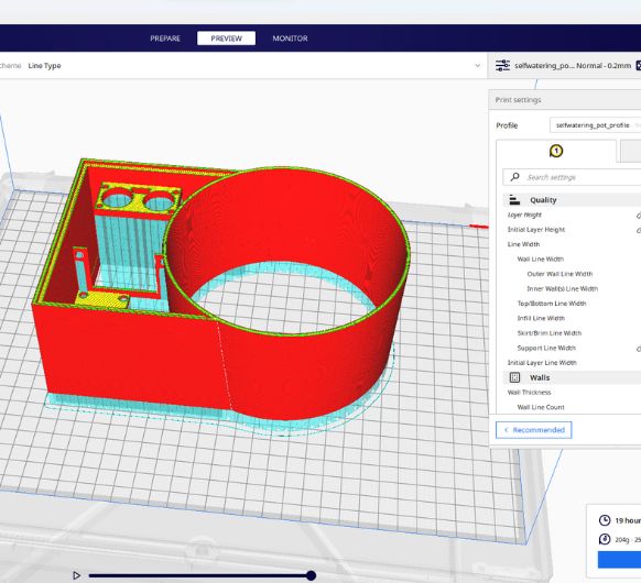
Electronics compartment in cura. Sliced and in preview mode. ~19h
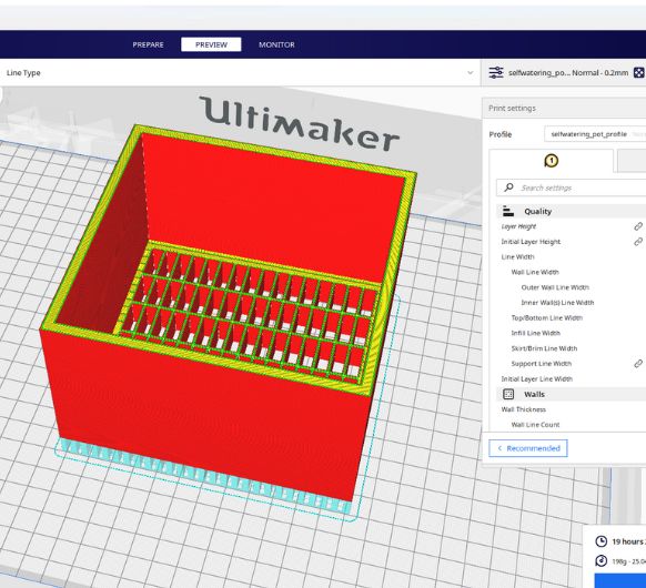
Gutter: ~19h
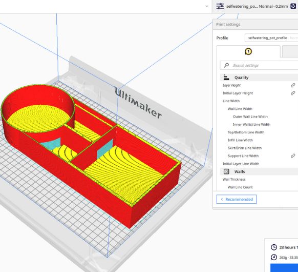
Watertank: ~1d
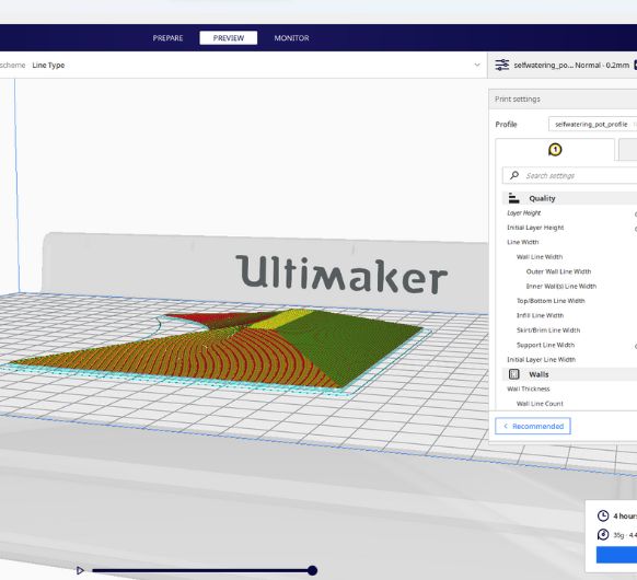
Electronics roof: ~4h

.jpg)
.jpg)
.jpg)
.jpg)
.jpg)
.jpg)
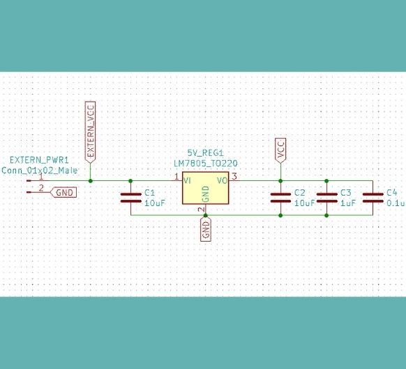
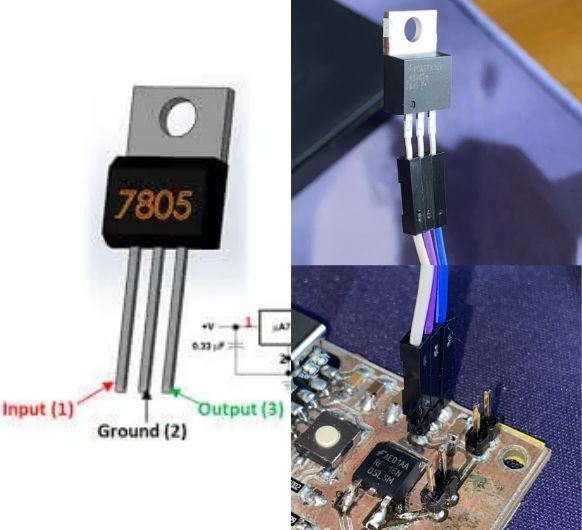 Connect the 5V regulator to the pin header. Mind the right orientation.
Input to 12V side, Ground to GND, Output to 5V side ->
You can check this in a datasheet or test it on a breaboar with a multimeter.
Connect the 5V regulator to the pin header. Mind the right orientation.
Input to 12V side, Ground to GND, Output to 5V side ->
You can check this in a datasheet or test it on a breaboar with a multimeter.
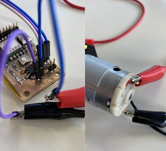 Connect
the pump: VCC to 12V and GND to common GND
Connect
the pump: VCC to 12V and GND to common GND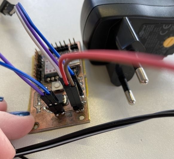 Connect the power adapter
(don't connect it to a power outlet yet): VCC
to VCC and GND to GND.
Connect the power adapter
(don't connect it to a power outlet yet): VCC
to VCC and GND to GND.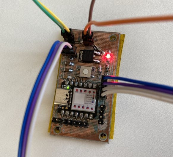 Connect
the
HC-SR04 to
the corresponding pins.
Connect
the
HC-SR04 to
the corresponding pins.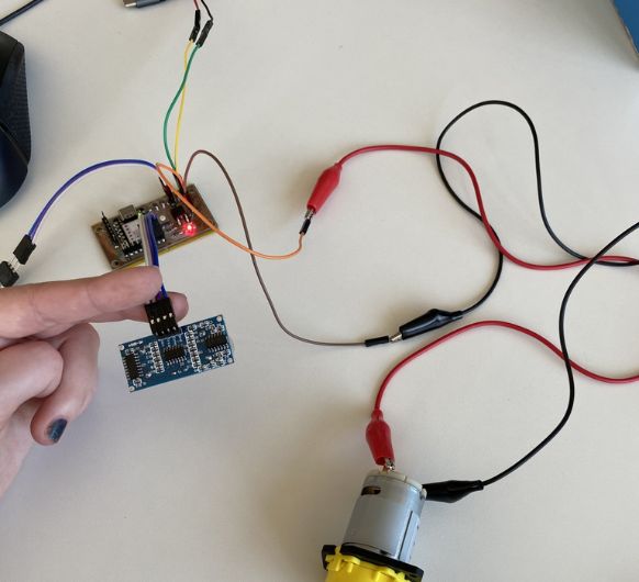 Overview:
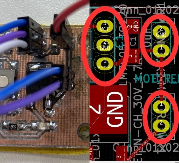 Make sure everything
is correctly connected. Check your KiCad design to
make sure.
Make sure everything
is correctly connected. Check your KiCad design to
make sure.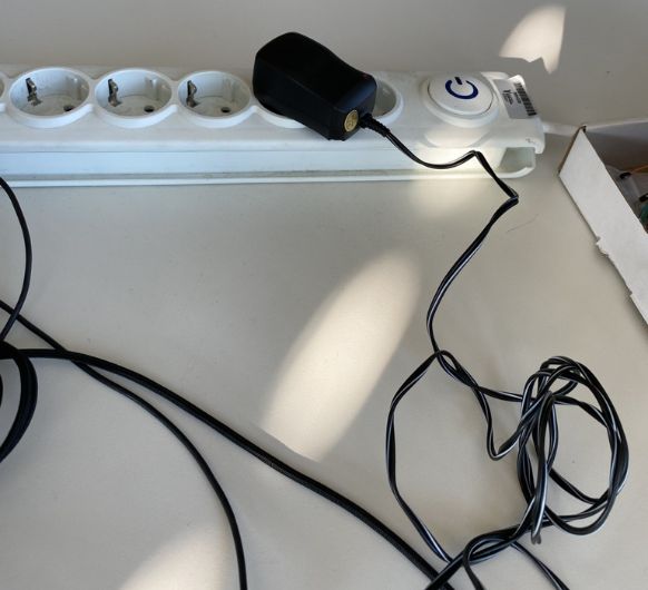 Now
connect
the power
adapter to a power outlet.
Now
connect
the power
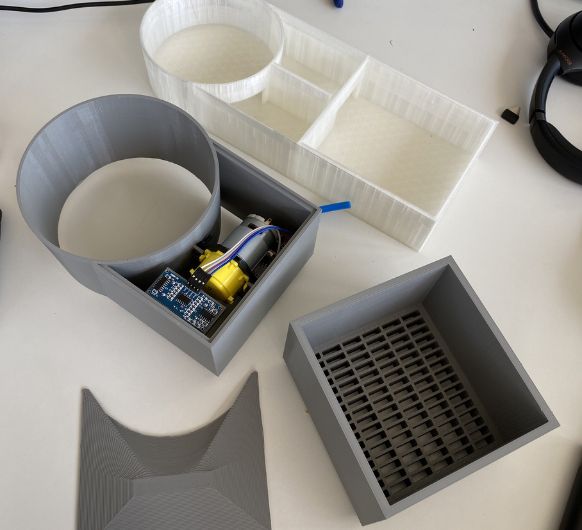
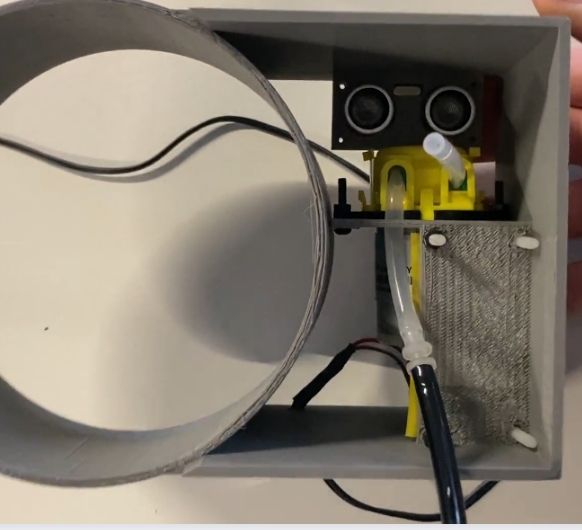
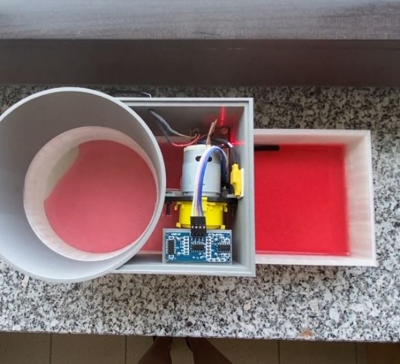
adapter to a power outlet.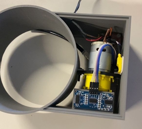 At the bottom you can
see the HCSR04 placed above the plants water tank. Right next to it is the peristaltic
pump, and below the peristaltic pump is my PCB. Everything is connected. The external
power supply can also be seen as the cable that leaves the electronics component.
At the bottom you can
see the HCSR04 placed above the plants water tank. Right next to it is the peristaltic
pump, and below the peristaltic pump is my PCB. Everything is connected. The external
power supply can also be seen as the cable that leaves the electronics component.
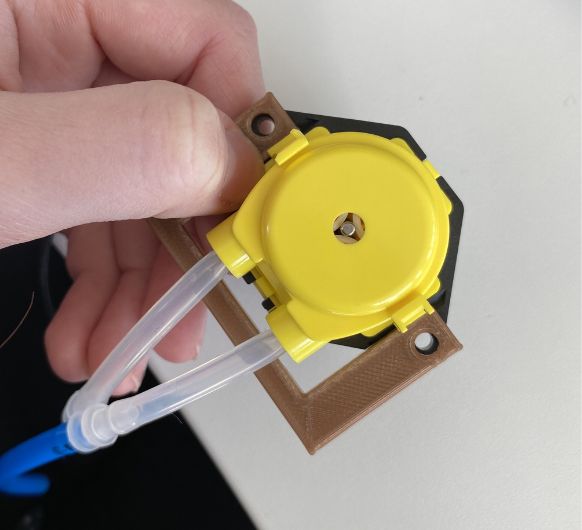
 View from below. You
can see emitter and receiver, as well as the pumps' two tubes. The black tube will go
into the reserve water tank and the other one will hang over the plants
watertank.
View from below. You
can see emitter and receiver, as well as the pumps' two tubes. The black tube will go
into the reserve water tank and the other one will hang over the plants
watertank.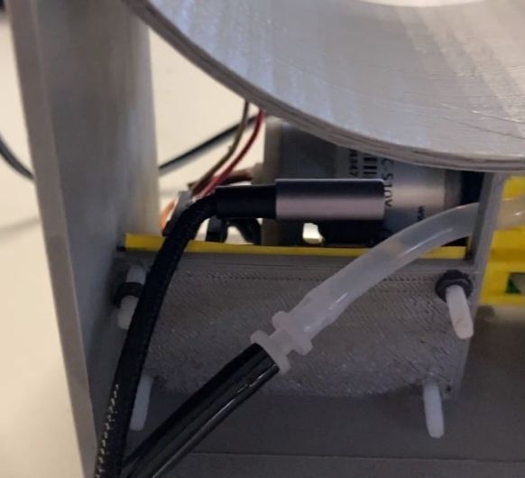 The PCB is already
programmed. But in case any changes need to be done, you can plug the USB cable in here
from underneath.
The PCB is already
programmed. But in case any changes need to be done, you can plug the USB cable in here
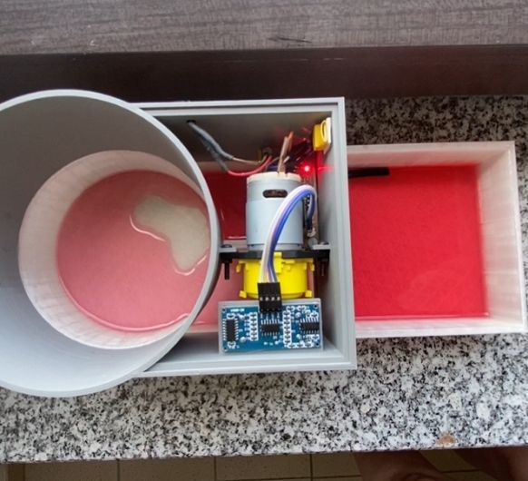
from underneath.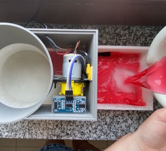 Case 1: The reserve
water tank has water inside.
Case 1: The reserve
water tank has water inside.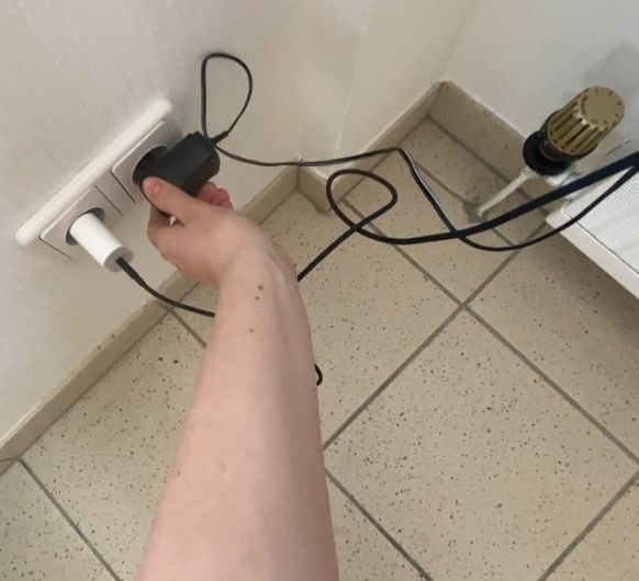 I plug in the power
supply.
I plug in the power
supply.
 Shortly after power
is supplied, the sensor will measure if the plant has water or not. If the plant
watertank is empty, it will advise the pump to pump from one tank to the other for 40
seconds.
Shortly after power
is supplied, the sensor will measure if the plant has water or not. If the plant
watertank is empty, it will advise the pump to pump from one tank to the other for 40
seconds.
 The sensor chekcs
the current waterlevel every minute. And as soon as the tank is (close to) empty, the
pump will pump as soon as the level gets checked again.
The sensor chekcs
the current waterlevel every minute. And as soon as the tank is (close to) empty, the
pump will pump as soon as the level gets checked again.
 Case 2: The reserve
watertank is empty.
Case 2: The reserve
watertank is empty.
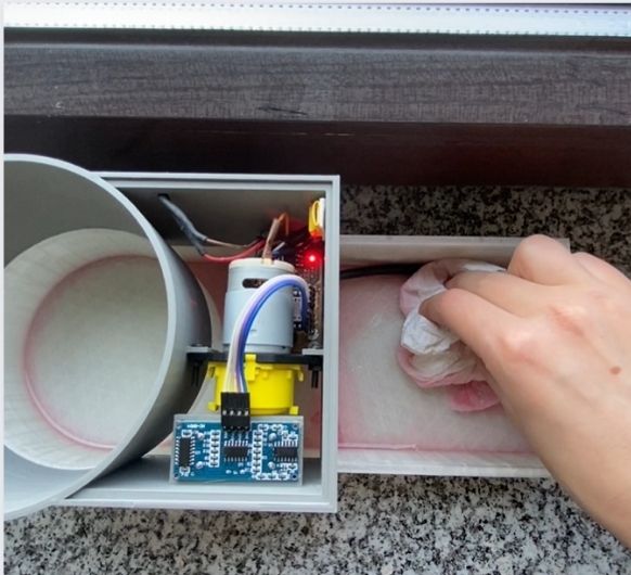
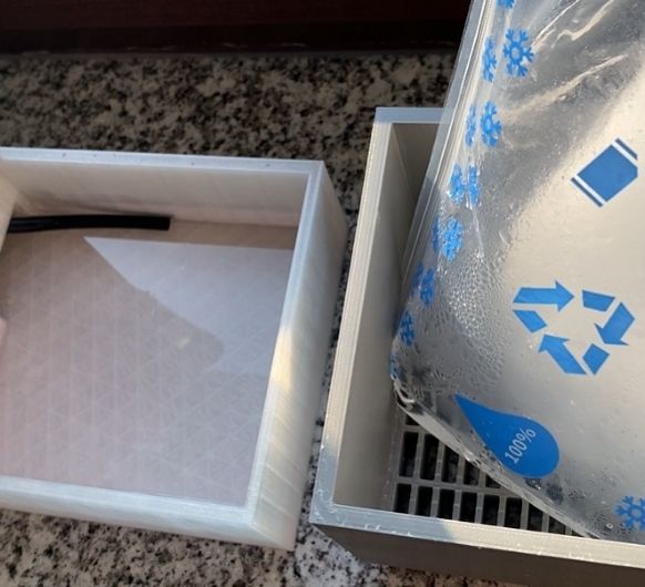 The reserve tank
will store the water until it gets used by the plant. As soon as the ice pack is empty,
you can remove the plastic.
The reserve tank
will store the water until it gets used by the plant. As soon as the ice pack is empty,
you can remove the plastic.
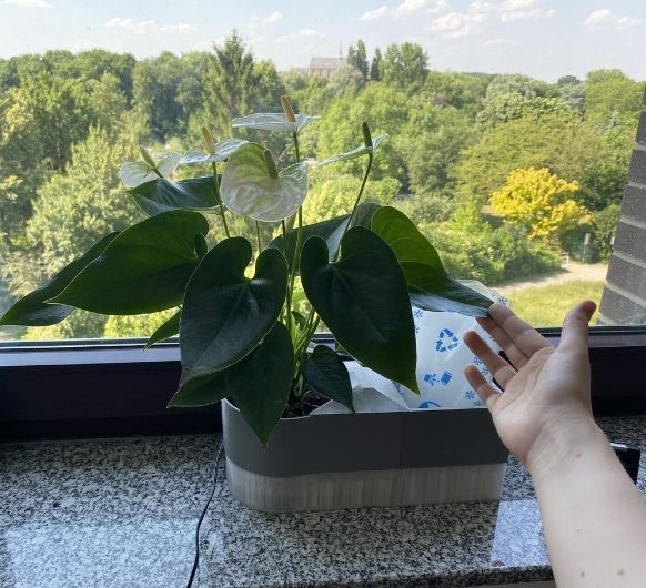 After 1 month of
using the flowerpot, the plant inside is still alive and well! :)
After 1 month of
using the flowerpot, the plant inside is still alive and well! :)