Output devices
Add an output device to a microcontroller board you've designed and program it to do
something.
Group assignment:
Group Assignment
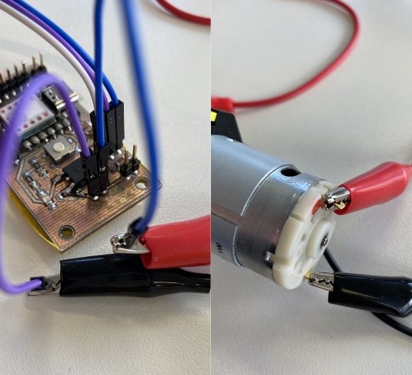
Measuring power consumption of peristaltic pump:
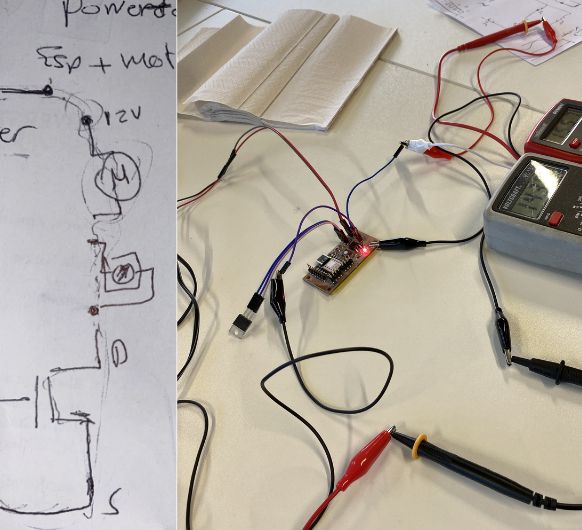 Connect two multimeters to your circuit. One to measure the Voltage,
positive goes to 12V VCC of the circuit and negative to tne common GND.
Another one to measure the current (Ampere): This multimeter gets inserted between
the 12VCC of the cicuit and the pumps VCC (handle it as if it's a wire).
Connect two multimeters to your circuit. One to measure the Voltage,
positive goes to 12V VCC of the circuit and negative to tne common GND.
Another one to measure the current (Ampere): This multimeter gets inserted between
the 12VCC of the cicuit and the pumps VCC (handle it as if it's a wire).
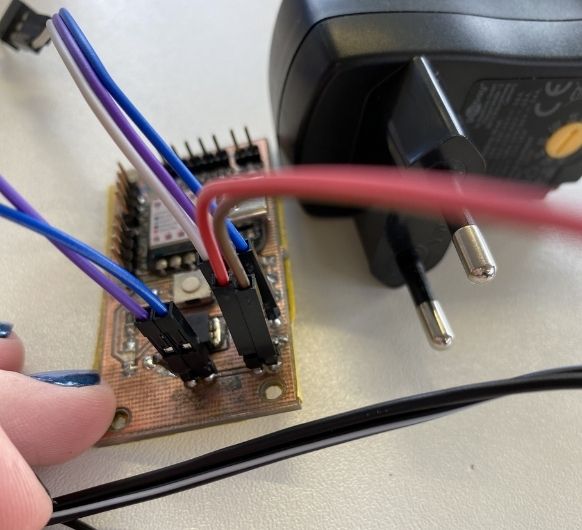
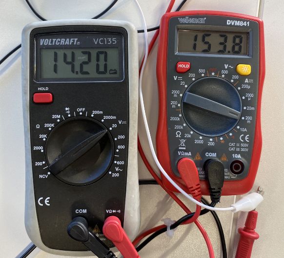 Now you can connect your
power adapter and see the values on the multimeters: ~14V and ~150mA
Now you can connect your
power adapter and see the values on the multimeters: ~14V and ~150mA
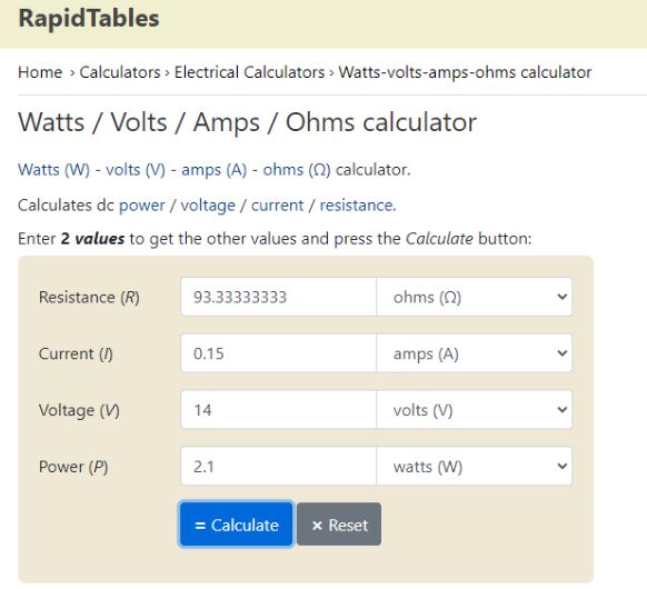 With these values you can now calculate the Watts: The pump needs
~2.1W
With these values you can now calculate the Watts: The pump needs
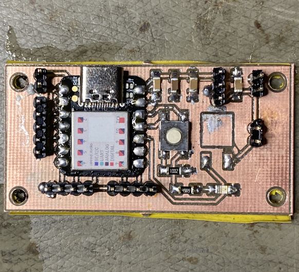
~2.1WDesign and fabrication of the PCB
You can see the documentation for this on my previous weeks' pages: Electronics design & Electronics production
Writing the program
It makes sense to program the microcontroller before connecting other devices, since they might
interfere with the upload connection for the code.
The program shown below defines the pin connected to the MOSFET's Gate as an output pin. Every 3
seconds, power is supplied to the pin, which bridges the connection between
the Drain and the Source of the MOSFET, connecting the GND of the pump to the common GND and
therefore enabling it to run:
// Define the MOSFET pin
const int MOSFET_PIN = 9;

void setup() {
  // Set the MOSFET pin as an output
  pinMode(MOSFET_PIN, OUTPUT);
}

void loop() {
  // Turn the MOSFET on
  digitalWrite(MOSFET_PIN, HIGH);

  // Wait for a short period of time
  delay(3000);

  // Turn the MOSFET off
  digitalWrite(MOSFET_PIN, LOW);

  // Wait for a short period of time
  delay(3000);
}Connection of the output device
I am using the waterpump as my output device this week.
A peristaltic pump is a special kind of pump that moves liquids using a flexible tube or hose.
It works in a similar way to how our muscles push food through our digestive system.
When the pump starts, one roller presses on the tube, squeezing it. This squeezing creates a
seal and prevents the liquid from going backward. Then, as the roller moves along the tube, it
pushes the squeezed portion of the tube forward, making the liquid move in the same direction.
This process repeats as the rollers keep moving, creating a continuous flow
of liquid through the pump.
It is a 12V pump and needs an external
powersupply as well as a MOSFET to control it.
MOSFETs (Metal-Oxide-Semiconductor Field-Effect Transistor) are commonly used as a switch or an
amplifier.
They have three terminals: the source, the gate, and the drain, and their conductive behavior is
controlled by the voltage applied to the gate.
Components mentioned:
- 5V regulator LM7805 (Input Voltage: Minimum 7V, Maximum 25V Output Current: 1.5A)
- 12V power adapter
- 12V peristaltic pump
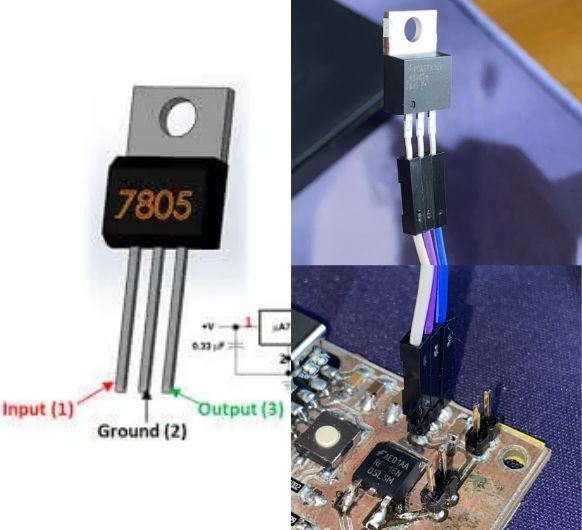 Connect the 5V regulator to the pin header. Mind the right orientation.
Input to 12V side, Ground to GND, Output to 5V side ->
You can check this in a datasheet or test it on a breaboar with a multimeter.
Connect the 5V regulator to the pin header. Mind the right orientation.
Input to 12V side, Ground to GND, Output to 5V side ->
You can check this in a datasheet or test it on a breaboar with a multimeter.
 Connect the pump: VCC to 12V and GND to common GND
 Connect the power adapter
(don't connect it to a power outlet yet): VCC
to VCC and GND to GND.
Connect the power adapter
(don't connect it to a power outlet yet): VCC
to VCC and GND to GND.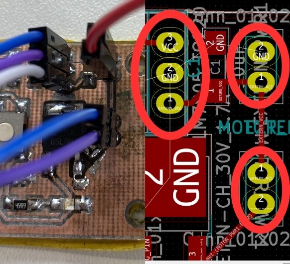 Make sure everything
is correctly connected. Check your KiCad design to
make sure.
Make sure everything
is correctly connected. Check your KiCad design to
make sure.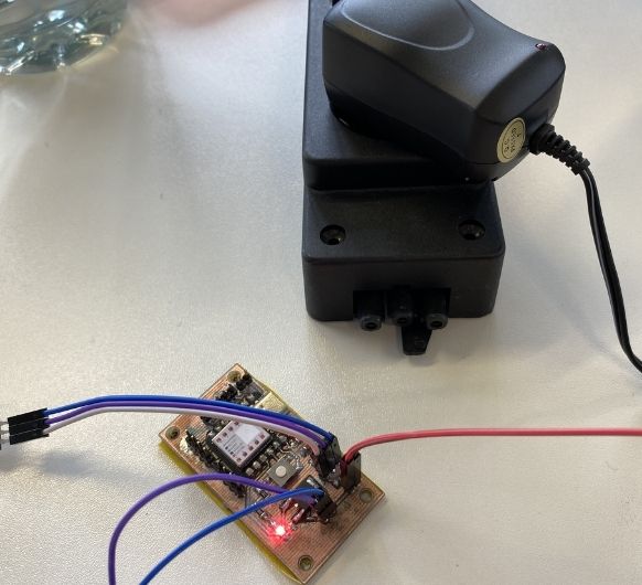 Now connect the power
adapter to a power outlet.
Now connect the power
adapter to a power outlet.
Troubleshooting
In reality it did not work on the first try. The KiCad footprint I used for the MOSFET was outdated and had the pads for Drain and Source switched. This caused the pump to not receive the right voltage and therefore not work. My instructor Ahmed helped me desolder the MOSFET with a hot air gun.
 We removed the
connection the Source pad had to the common GND as well as the connection the Drain
pad had to the GND of the pump.
We removed the
connection the Source pad had to the common GND as well as the connection the Drain
pad had to the GND of the pump.
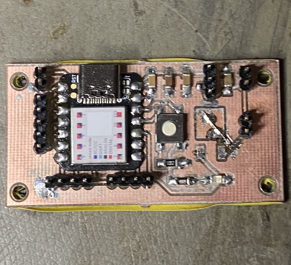 We added a bridge
using a small string of copper and solder to connect the Source to the pump GND and
the Drain to the common GND.
We added a bridge
using a small string of copper and solder to connect the Source to the pump GND and
the Drain to the common GND.