Electronics production
Redraw one of the echo hello-world boards or something equivalent, add (at least) a
button and LED (with current-limiting resistor) or equivalent input and output, check the
design rules, make it, test it. Optionally, simulate its operation.
Group assignment:
Group Assignment
The following are good test files, if you are using SVG's in your workflow.
 Traces test file
 Outline test file
But our Lab has a new CNC that works with Gerber and not direct G-Code (so I can skip the whole SVG to PNG to Mods process - pretty cool!). But this also means that I can't work with this SVG test file for our CNC. So my instructor Ahmed and I designed a test file in KiCad:
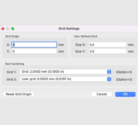 We changed the grid to something we could easily work with.
All of the following lines will be 0.5mm apart.
We changed the grid to something we could easily work with.
All of the following lines will be 0.5mm apart.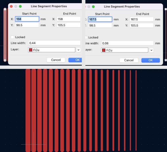 Now we created different sized lines, the thickest being 0.44mm and the thinnest 0.08mm.
20 lines total, each 0.02mm thinner/thicker than the next.
Now we created different sized lines, the thickest being 0.44mm and the thinnest 0.08mm.
20 lines total, each 0.02mm thinner/thicker than the next.
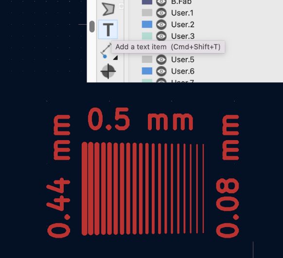 Some text to make it easier to understand what's what. 0.5mm is the distance between the
center of all lines, and left is thickest, right is thinnest line.
Some text to make it easier to understand what's what. 0.5mm is the distance between the
center of all lines, and left is thickest, right is thinnest line.
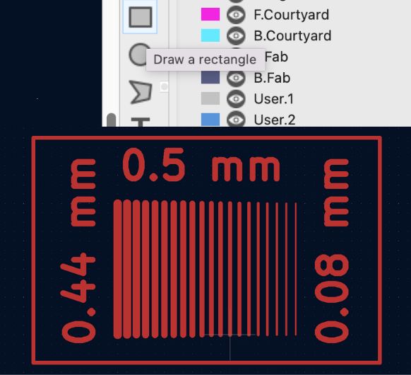 Rectangle around everything for the edge cut.
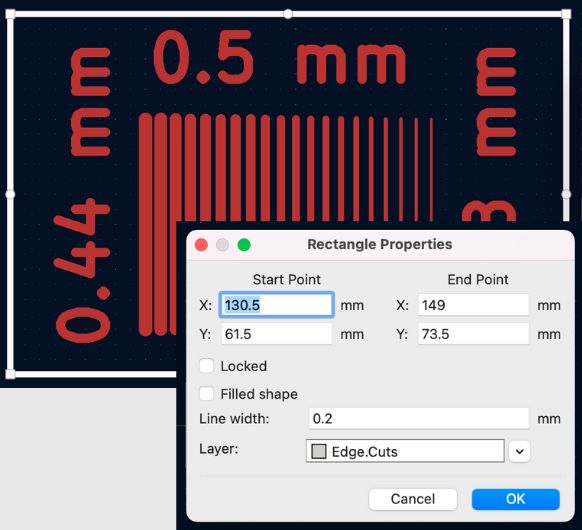 Putting the rectangle on the Edge cuts layer.
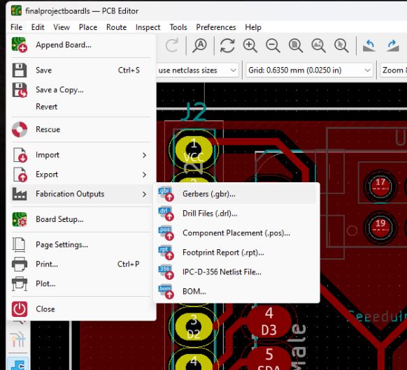
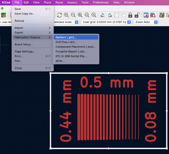 Exporting as Gerber.
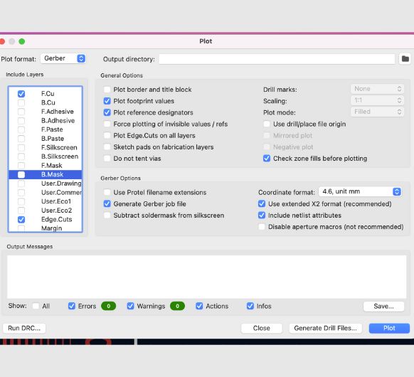 Choose which layers to include: F.Cu and Edge.Cuts.
After plotting this file, save it to an USB and head over to the CNC.
copper Layer gerber file
edge cuts gerber file
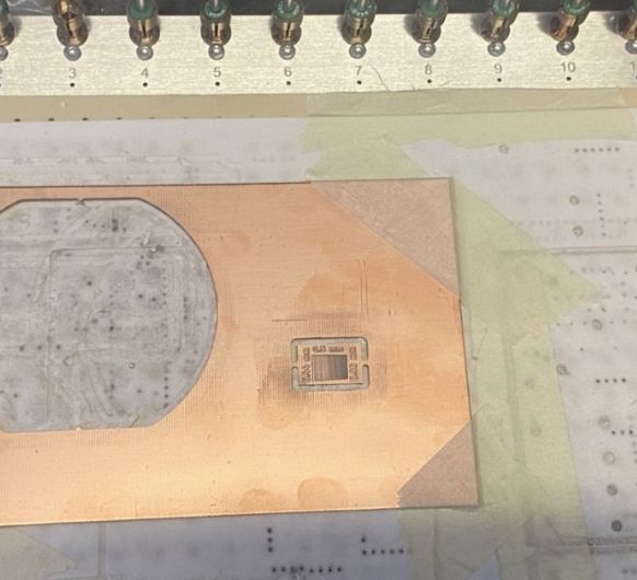 Here's the milled test board.
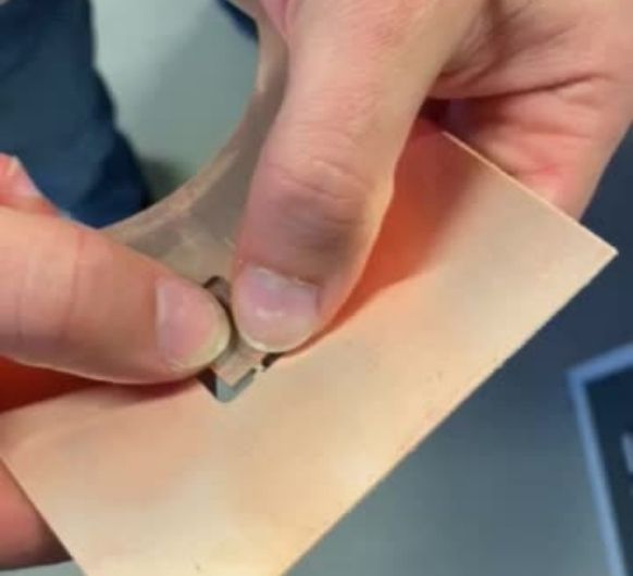 Break the tabs to remove the board from the plate.
The result:
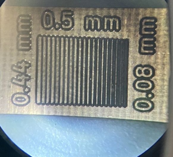 Under a microscope. Outof the 20 lines, about 17 were properly milled and are still
visible/reliable. Only the last 3 - 4 would probably be insufficient for a real pcb,
while all of the bigger lines probably would work perfectly fine. But you can also see
how
the spacing doesn't get significantly thinner on the left side. So minimum spacing is
around ~0.25mm.
Under a microscope. Outof the 20 lines, about 17 were properly milled and are still
visible/reliable. Only the last 3 - 4 would probably be insufficient for a real pcb,
while all of the bigger lines probably would work perfectly fine. But you can also see
how
the spacing doesn't get significantly thinner on the left side. So minimum spacing is
around ~0.25mm.
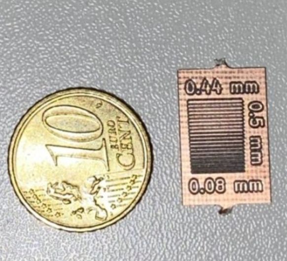 Comparison to a 10 cents coin. This machine is really precise!
Milling my PCB
For this assignment, I am taking my design from electronics design week.
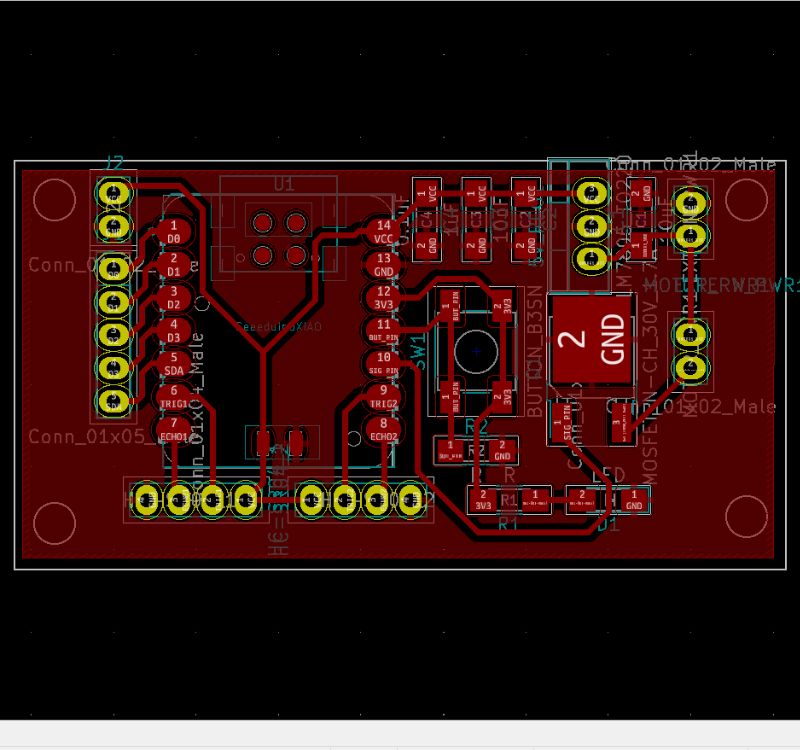
 As already
described above in the Group Assignment, export you file as Gerber first and make sure
to
include all the right layers. Save it on USB. Then head over to your CNC.
As already
described above in the Group Assignment, export you file as Gerber first and make sure
to
include all the right layers. Save it on USB. Then head over to your CNC.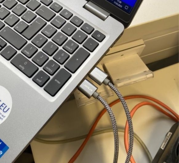 First, connect
the machine to the Laptop.
First, connect
the machine to the Laptop.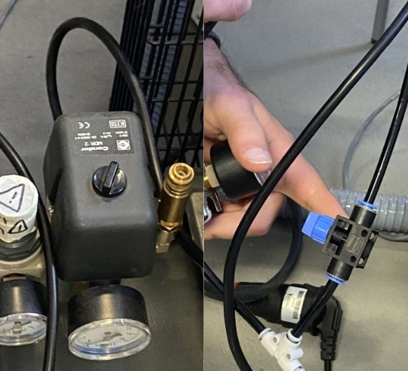 Turn on the air compressor
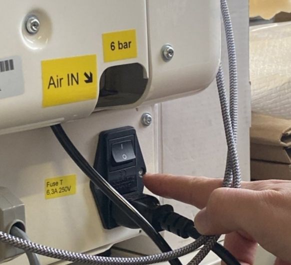 Turn on the CNC ( this order is important, NEVER turn on the CNC BEFORE connecting it to
the PC.)
Turn on the CNC ( this order is important, NEVER turn on the CNC BEFORE connecting it to
the PC.)
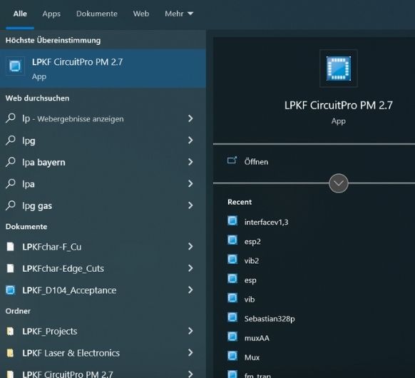 Start the software
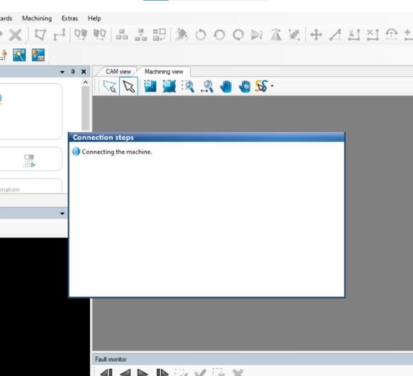 Connection process
 If a warning like this pops up, check the compressor again to see if it's really on and
working.
If a warning like this pops up, check the compressor again to see if it's really on and
working.
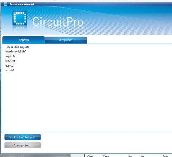 Make a new document.
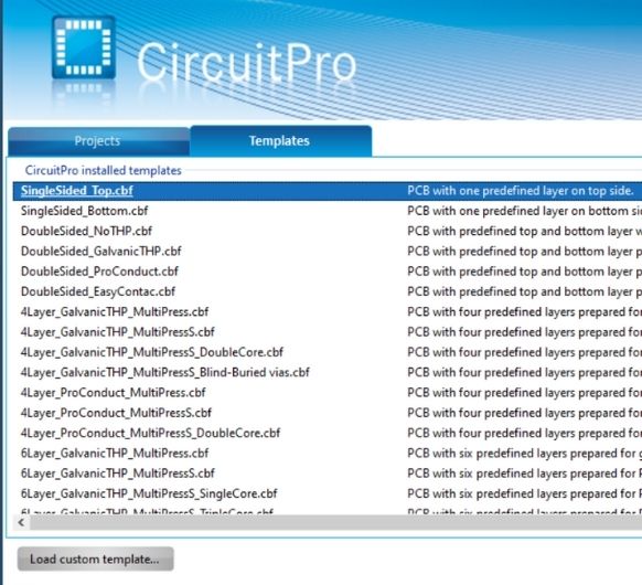 Choose the single sided top template.
 Should look like this.
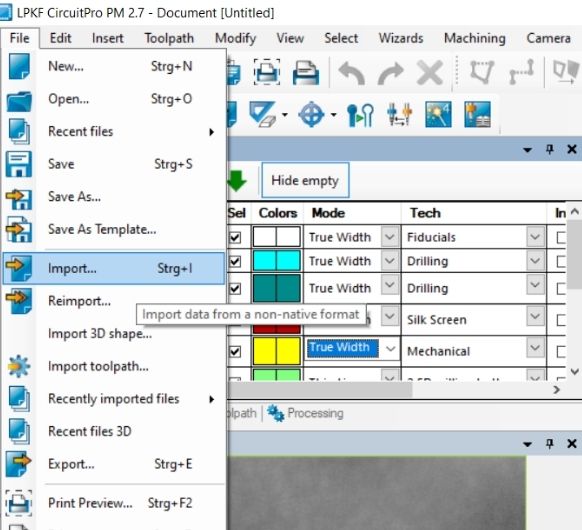 Now import your files.
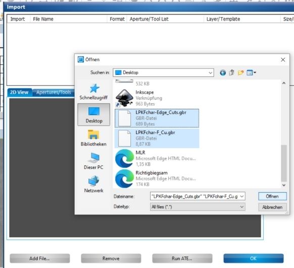 Select both copper layer and edge cuts.
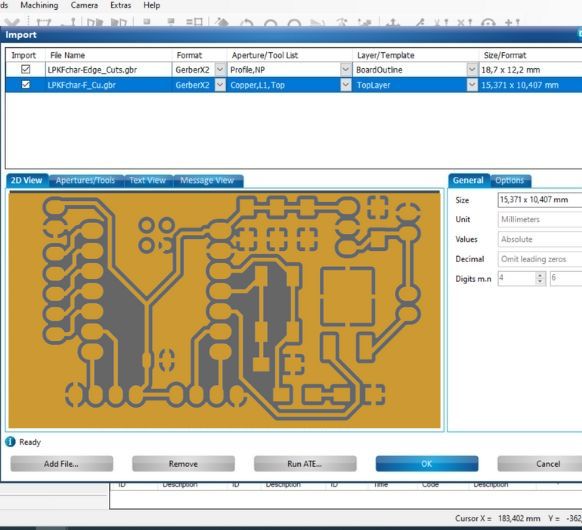 You will get this preview, make sure the settings are right and the files are on the
right layer, click ok.
You will get this preview, make sure the settings are right and the files are on the
right layer, click ok.
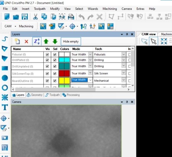
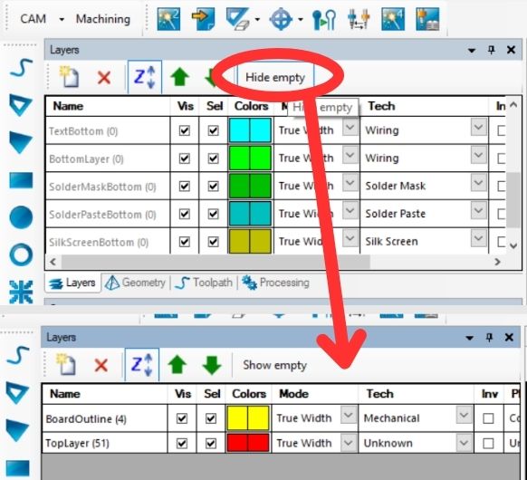 Hide the empty layers.
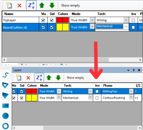 Adjust the settings for the layers and the order. Top layer should be first with True
Width and Milling Top settings. BoardOutline should be last with mechanical and contour
routing setting.
Adjust the settings for the layers and the order. Top layer should be first with True
Width and Milling Top settings. BoardOutline should be last with mechanical and contour
routing setting.
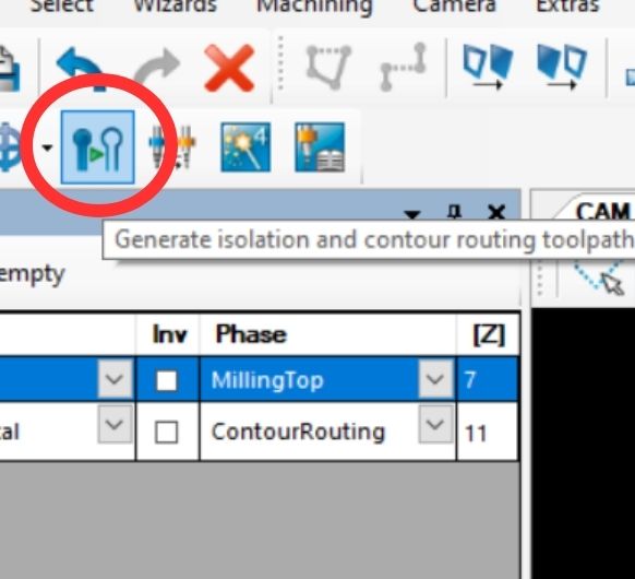 Click generate isolation and contour routing toolpath.
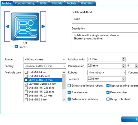 Choose the tool for isolating (top layer).
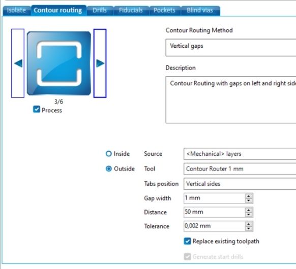 And the tool for contour routing (edge cuts).
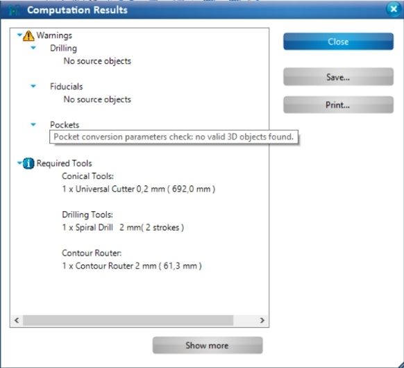 Check for any important warnings after the computation is done. Then click ok.
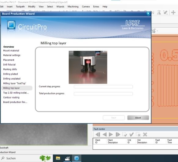
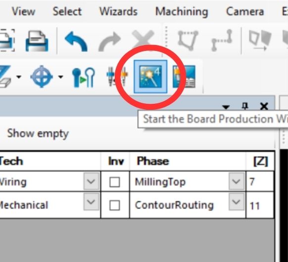 Now start the board production wizard.
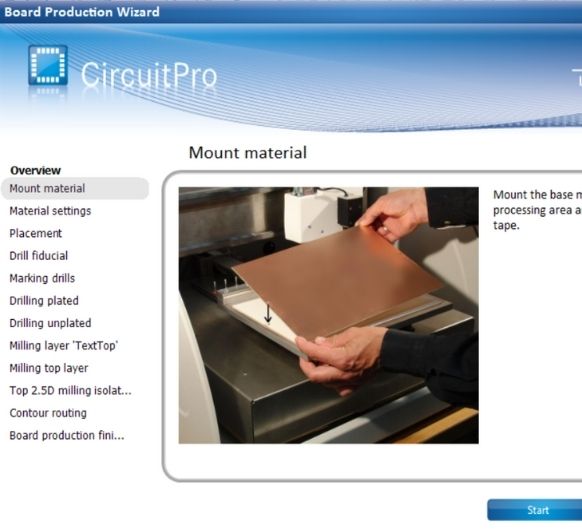 This will pop up.
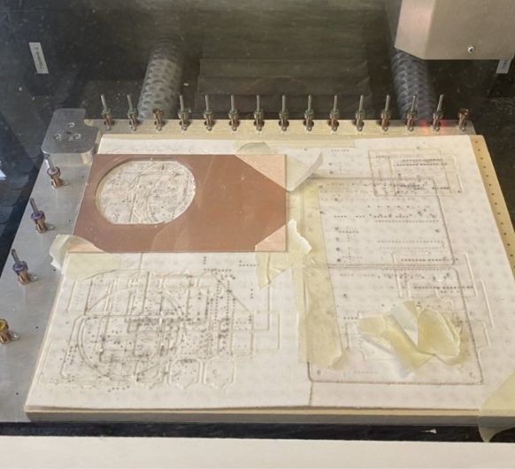 So now you can mount the material, fix it at some edges with tape.
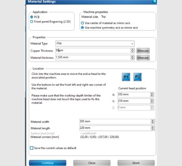 After you've done so, in this next screen you can change the material settings. Make
sure Material Type, Copper Thickness and Material Thickness are right.
After you've done so, in this next screen you can change the material settings. Make
sure Material Type, Copper Thickness and Material Thickness are right.
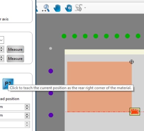 This screen will also let you choose the position of the material on the milling plate.
Define where your copper plate lies on the machine, use the green and purple dots for
orientation.
This screen will also let you choose the position of the material on the milling plate.
Define where your copper plate lies on the machine, use the green and purple dots for
orientation.
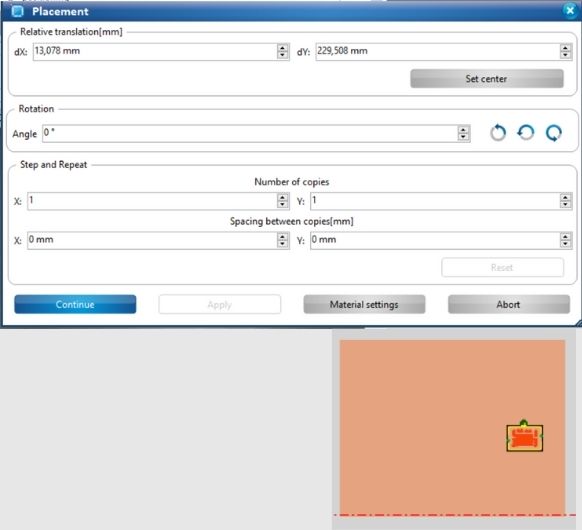 Now define where your PCB should be milled on the material you put inside.
 Now this screen will show, preparing the milling process.
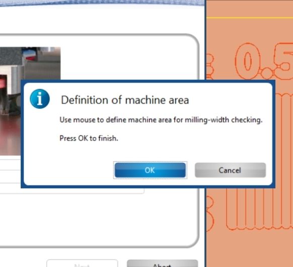 It will ask for you input. With this you can choose where the test line for
auto-focusing will be milled, you can press ok.
It will ask for you input. With this you can choose where the test line for
auto-focusing will be milled, you can press ok.
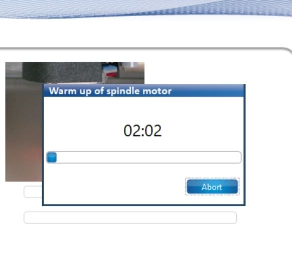 Spindle will warm up. This takes a few minutes.
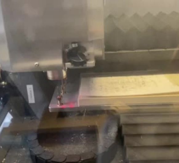
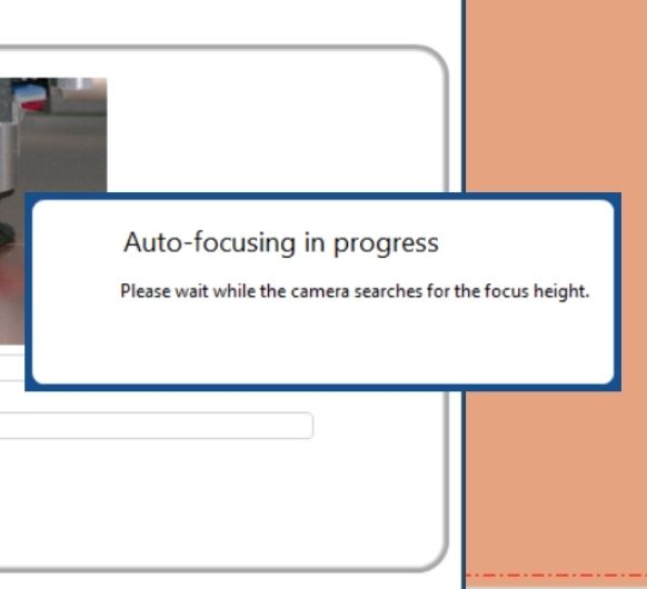 The machine then starts it's auto-focusing process.
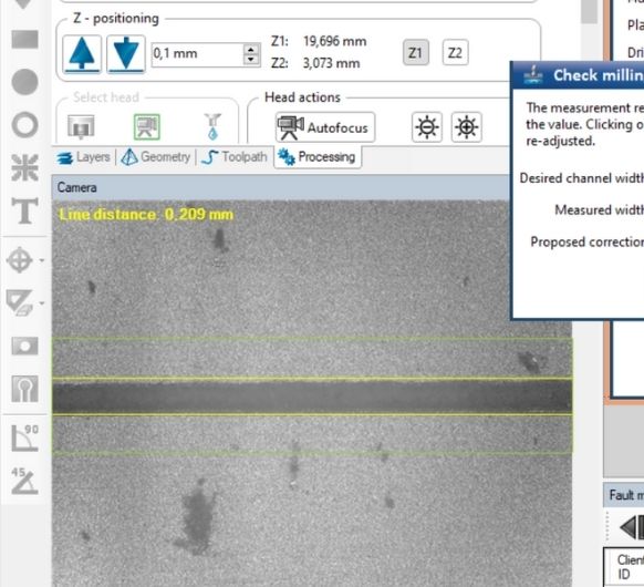 It has a camera which recognizes the previously milled line.
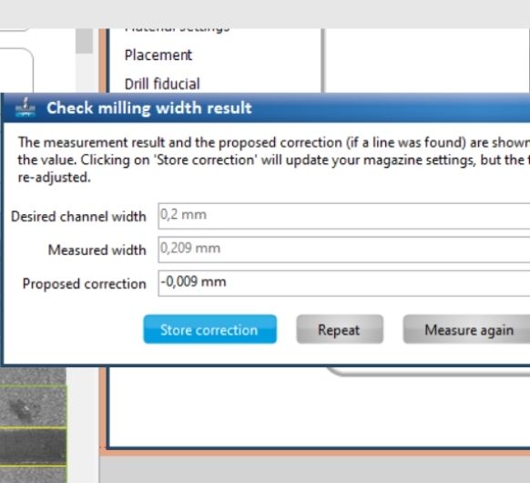 If you think the machine found the line correctly you can click store correction to set
the focus.
If you think the machine found the line correctly you can click store correction to set
the focus.
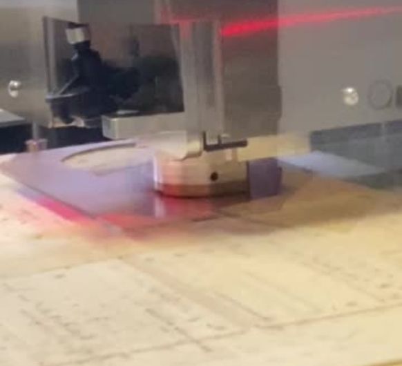
 The machine will get the tool by itself and will check the z height as well all on its'
own.
The machine will get the tool by itself and will check the z height as well all on its'
own.
 Milling the top layer.
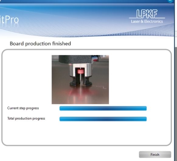 The program will tell you when the machine is finished.
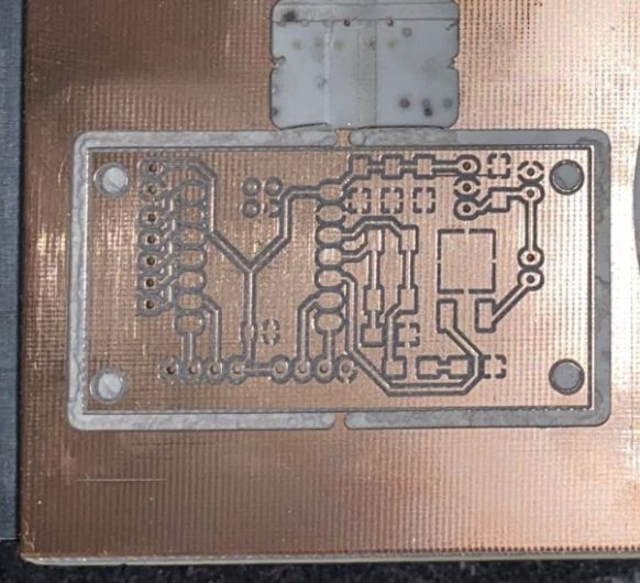 Here's the milled board.
Break the tabs just like for the GA to remove the board from the plate.
Here's the milled board.
Break the tabs just like for the GA to remove the board from the plate.
Soldering the components
Now the milled PCB had to be stuffed/soldered. To do so, the first step is to get all the materials:
| Name | Description | Amount |
|---|---|---|
| Controller | Seeeduino XIAO SAMD21 | 1 |
| Pin-Header | Conn_02 Male | 3 |
| Pin-Header | Conn_04 Male | 2 |
| Pin-Header | Conn_05 Male | 1 |
| LED (R_1206) | LED indicates power | 1 |
| Capacitor (C_1206) | 10uF | 2 |
| Capacitor (C_1206) | 1uF | 1 |
| Capacitor (C_1206) | 0.1uF | 1 |
| Resistor (R_1206) | 49Ω | 1 |
| Resistor (R_1206) | 10kΩ | 1 |
| Button | 4 Pins SMD | 1 |
| Voltage Regulator | 5V | 1 |
| MOSFET SMD | 50V 16A | 1 |
After soldering this is what my PCB looks like:
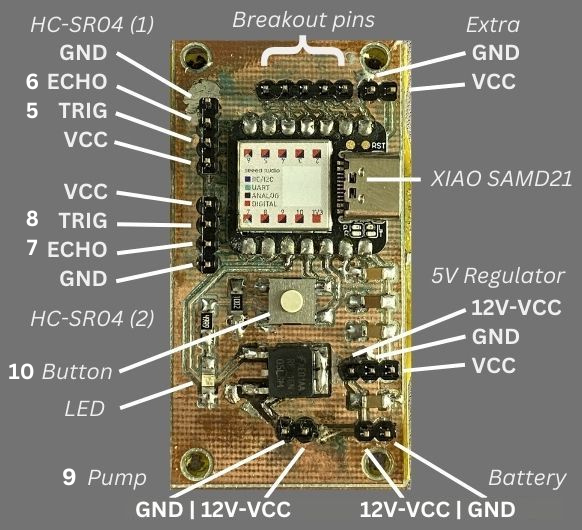
- 2x HC-SR04 (GND, ECHO,TRIG, VCC)
- Pump (12V, GND)
- other components, see picture
The board also includes a programmable button and an LED that turns on on receiving power.
Testing the functionality/programming
For more in-depth info about programming the SAMD21, please refer to my Embedded Programming assignment.
I intend to do a simple program to show the functionality of the board.
In the following code, I first declare two variables:
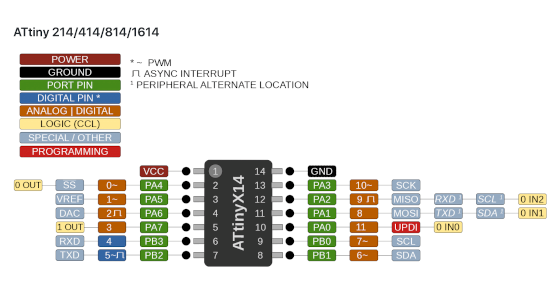
"button", which holds the pin number
of
the
button I'm using, and count, which will keep track of how many times the button has been
pressed.
In setup(), I set "button" as an input using the pinMode() function, and
initialize serial communication at a baud rate of 9600 using the Serial.begin() function.
In the loop, I check if the button is pressed using the digitalRead() function as well as
checking if it was not previously pressed using the buutonPressed boolean. If
this is true, I increment the count variable and output the count value to the serial monitor
using the
Serial.println() function.
If the button is not pressed, we update the buttonPressed variable to false, which will allow
the counter to increment again when the button is pressed the next time.
int button = 10; // the pin number of the button
int count = 0; // the initial count value
bool buttonPressed = false; // state variable to keep track of button press

void setup() {
	pinMode(button, INPUT); // set the button pin as an input
	Serial.begin(9600); // initialize serial communication at 9600 baud rate
}

void loop() {
	if (digitalRead(button) == HIGH && !buttonPressed) { // if the button is pressed and was not previously pressed
	count++; // increment the count
	Serial.println(count); // output the count value to the serial monitor
	buttonPressed = true; // update the state variable
	} else if (digitalRead(button) == LOW) { // if the button is not pressed
	buttonPressed = false; // reset the state variable
	}
}
(This code was written by ChatGPT and edited by me)
The code should continuously loop and increment the count value by 1 each time the button is pressed. You can view the count value on the serial monitor by selecting the correct baud rate (9600) in the IDE and opening the serial monitor.
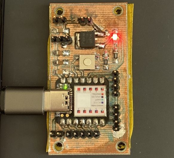 By connecting the PCB to my PCB, it receives power. This causes the LED to turn on, as it should!
Bonus:
Workflow with MODS and the Roland MDX 40 CNC:
Last year I worked with the Roland MXD 40 which needed it's files to be prepared with MODS, so let me also show you the workflow for that:
Preparing the files (InkScape, GIMP, Mods)
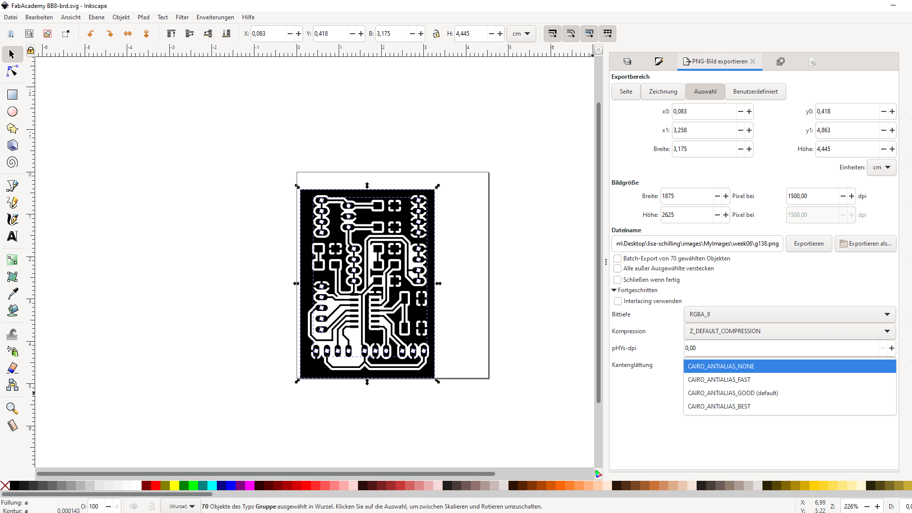
InkScape
As soon as the SVG is exported from KiCad, you can open the it in Inkscape to convert it into png. To do so, open the file and select everything. After everything is selected, change antialiasing to none and export the file as png.
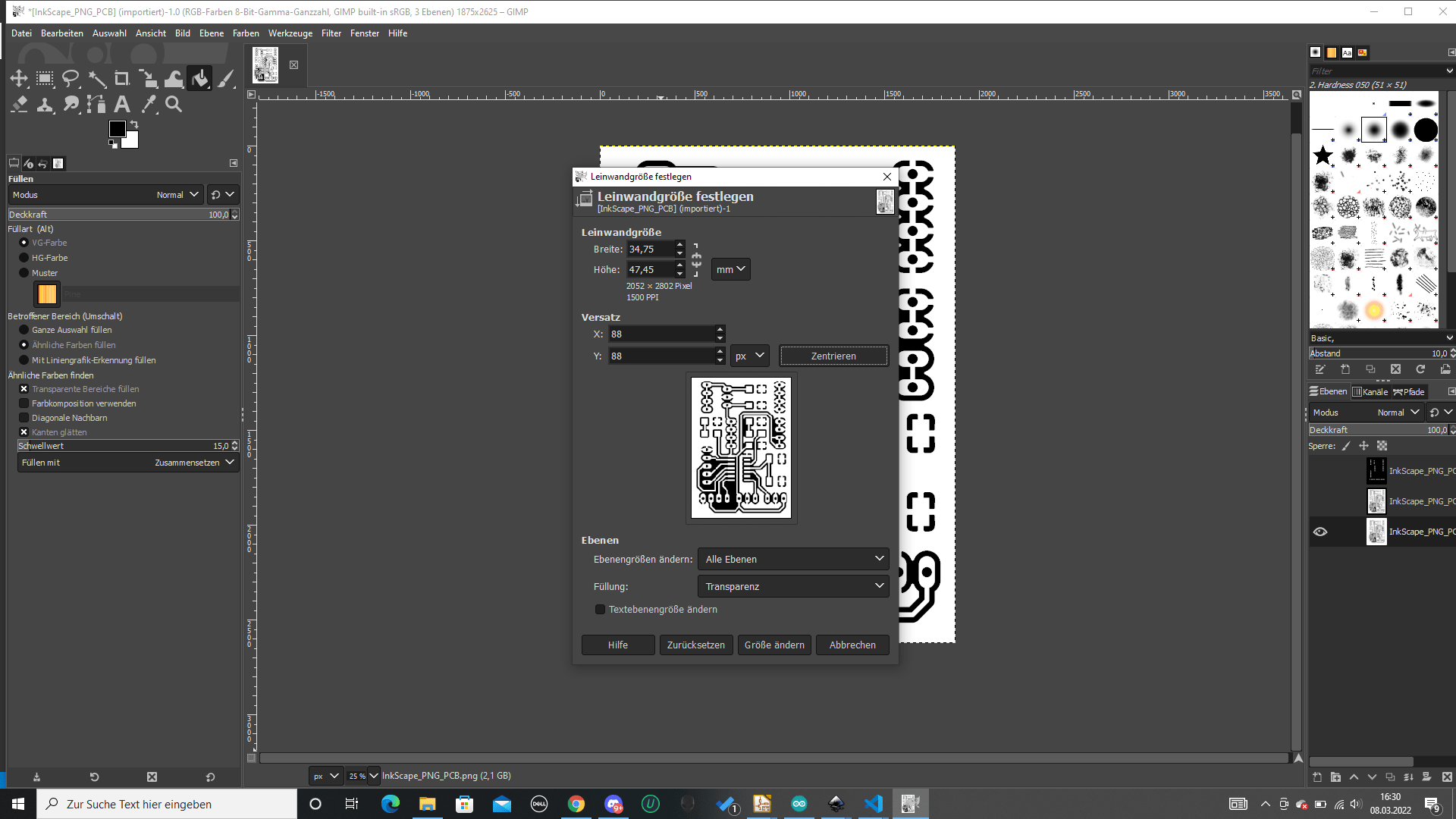
GIMP
Now to GIMP: Open the png file in Gimp. Go to "Bild" and "Leinwandgröße", change pixels to millimeters and add 3 to x and y. Click "Zentrieren" to center it. If you are left with a yellow border, that is not completely on the outside of the image, go to "Bild" again and click "Ebenen zusammenfügen". Otherwise you wont be able to add color to the new space as there is not a layer there yet.
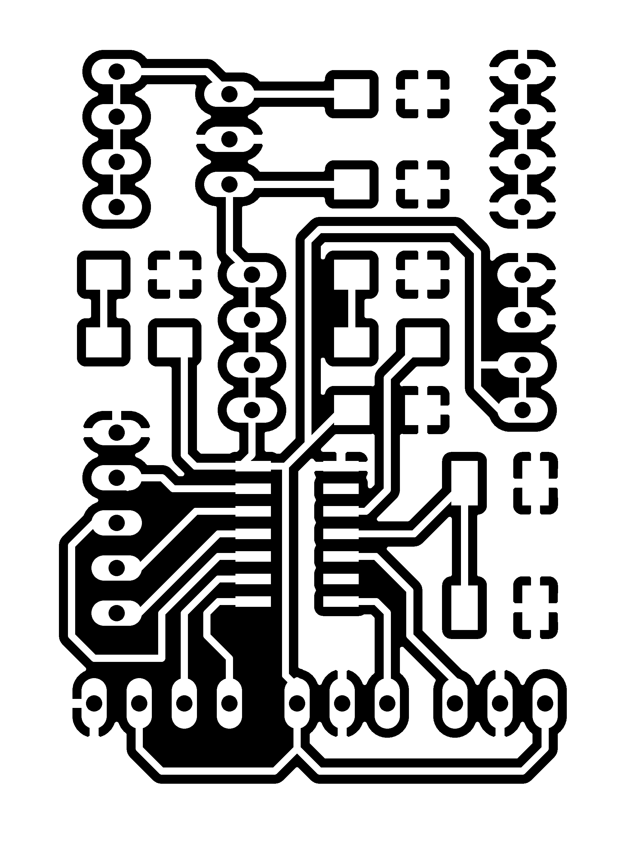 Traces: The traces should be white and the outside black (the black
part will be cut). Also turn the holes white!
Traces: The traces should be white and the outside black (the black
part will be cut). Also turn the holes white! Holes: Turn everything black except the holes.
 Cutout: Make a rectangular selection inside of the image close to the
borders. Go to "Selection" and chose the option which will round the edges (round
edges by 15).
Cutout: Make a rectangular selection inside of the image close to the
borders. Go to "Selection" and chose the option which will round the edges (round
edges by 15).Mods
How to convert these files into .rml files that can be used with the local Roland MDX-40 CNC (taken from the MODS tutorial, find it here ):
- Right click anywhere and select PROGRAMS -- select OPEN SERVER PROGRAM
- Select ROLAND > MILL > MDX20 (choose the machine closest to the one you have) and now PCB
- Another module is needed to make it save the file automatically: Right click anywhere in the white space and select MODULE > OPEN SERVER MODULE > SAVE FILE
- Now connect the elements by clicking on OUTPUT of Roland-20-milling-machine and clicking again in INPUT of the save file module to make the connection/wiring between them.
Traces:
- Go to READ PNG MODULE SELECT- PNG FILE - select your traces image
- In SET PCB Default module click in MILL TRACES 1/64
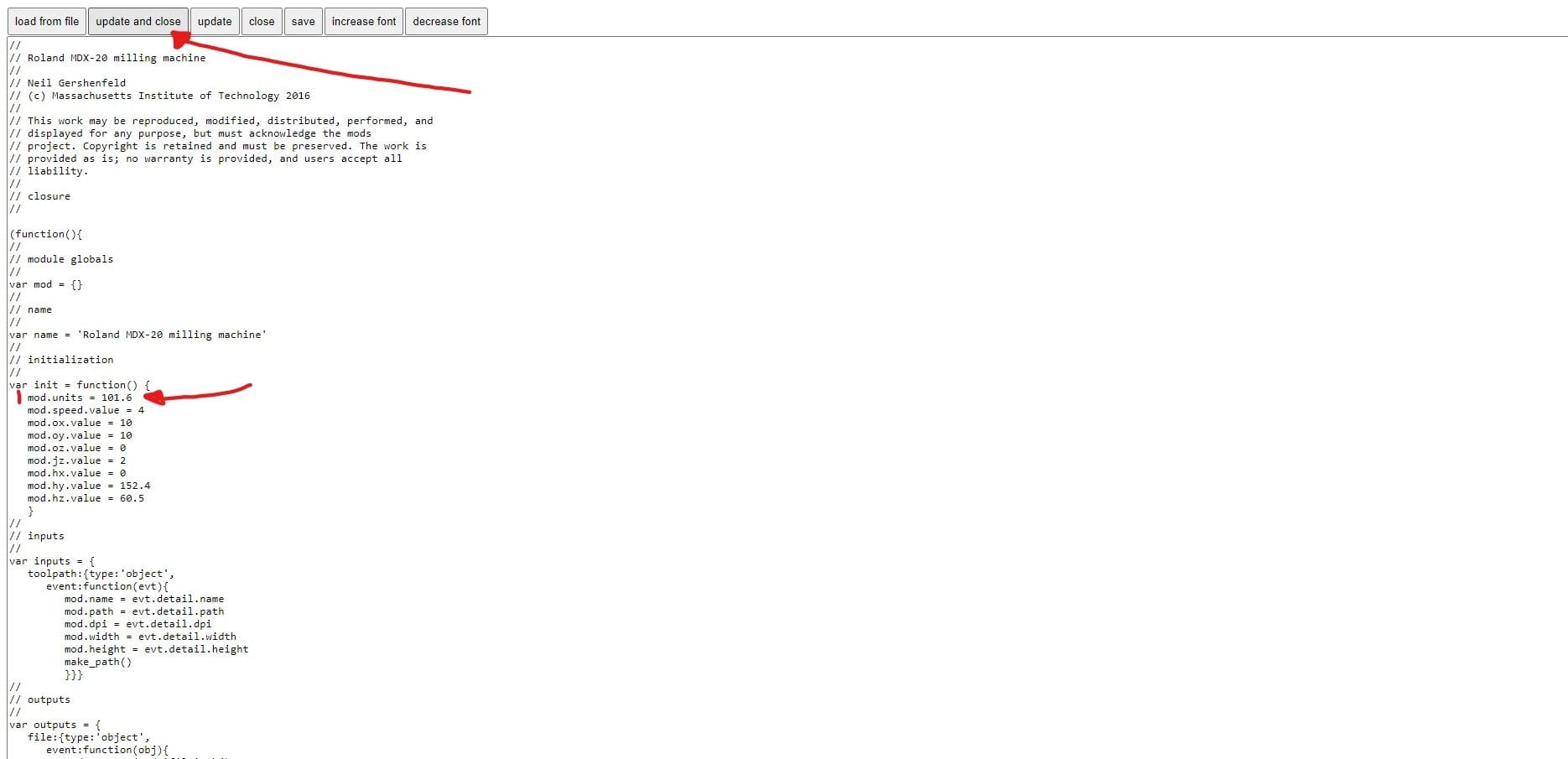
- Adjust the settings according to this screenshot (Attention: To have the right settings for our local machine, you also need to edit some units of the Roland MDX-20 milling machine module. See green mark):
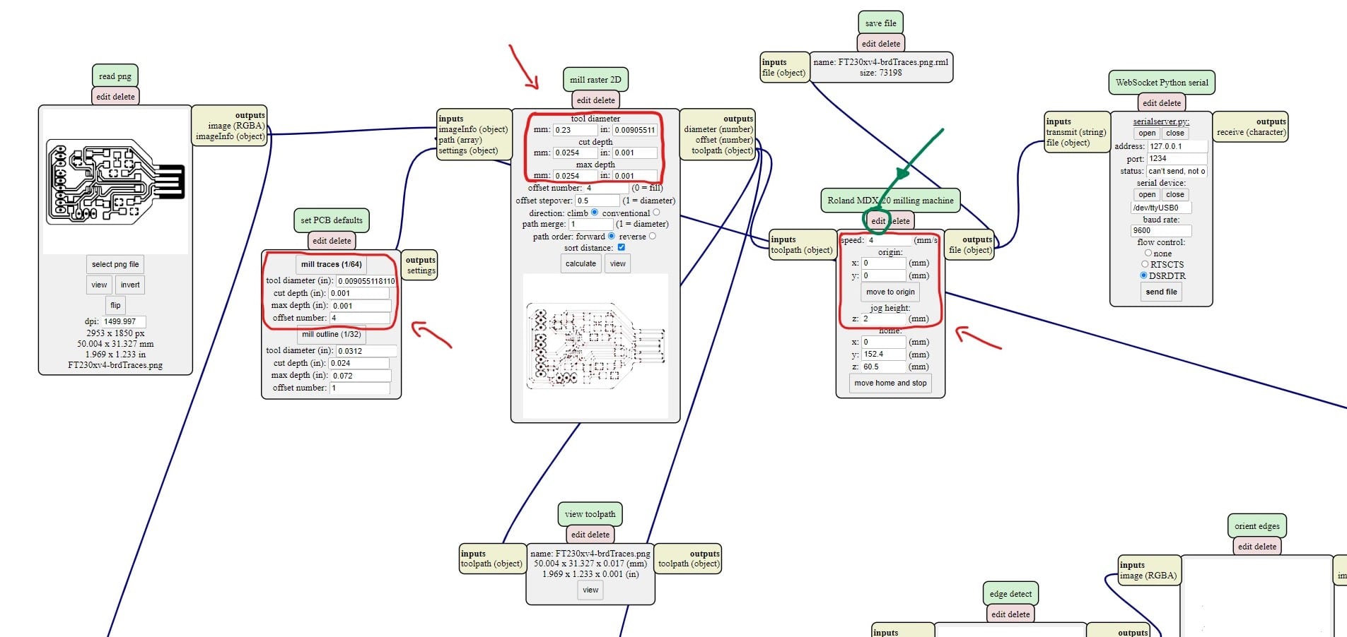
- In Mill Raster 2D module click Calculate and the .rml file will be saved to your PC
- Go to READ PNG MODULE SELECT- PNG FILE - select your cutout/holes image
- In SET PCB Default module click in MILL OUTLINE 1/32
- Adjust the settings according to this screenshot (Attention: To have the right settings for our local machine, you also need to edit some units of the Roland MDX-20 milling machine module. See green mark of image above):
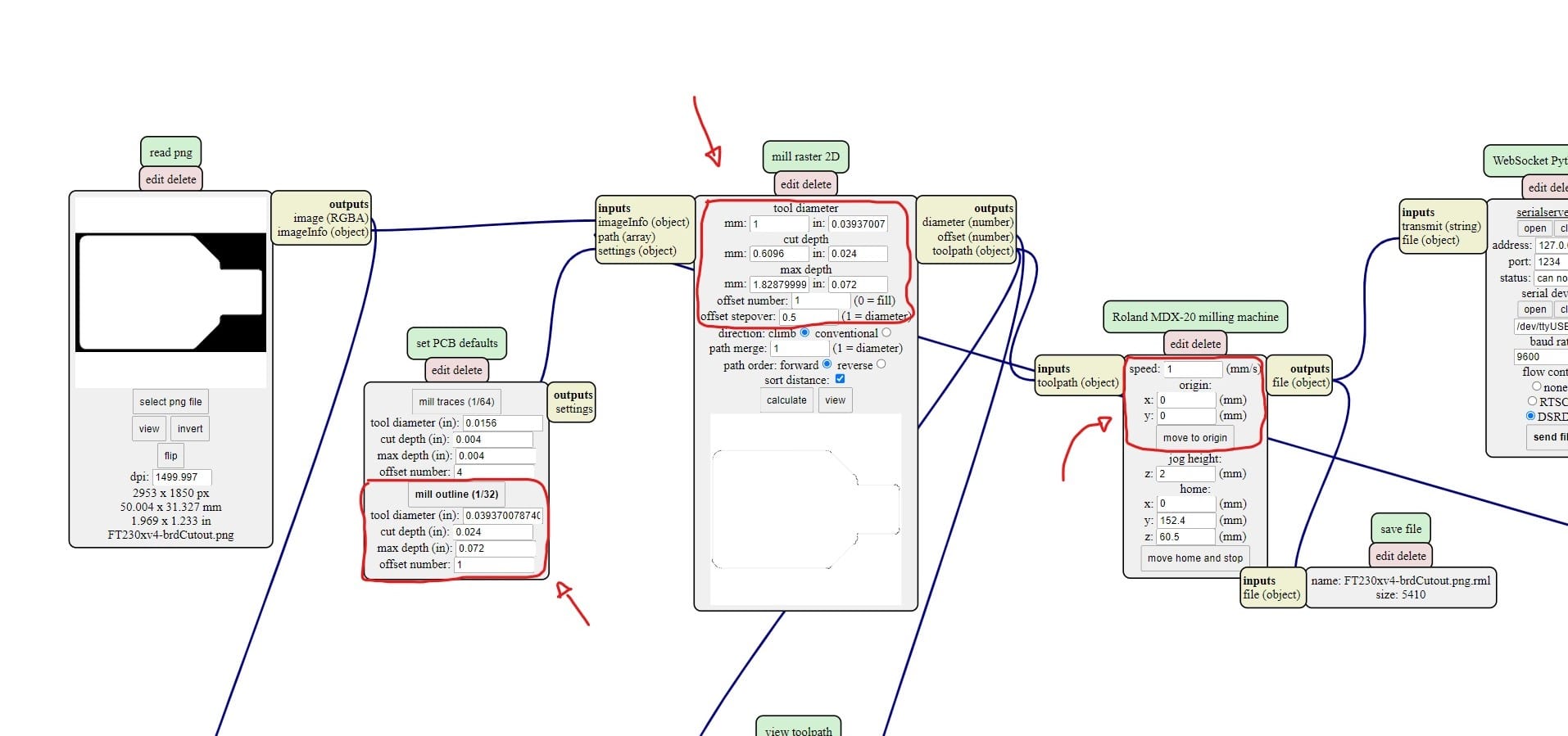
- In Mill Raster 2D module click Calculate and the .rml file will be saved to your PC
CNC-Milling
Traces:
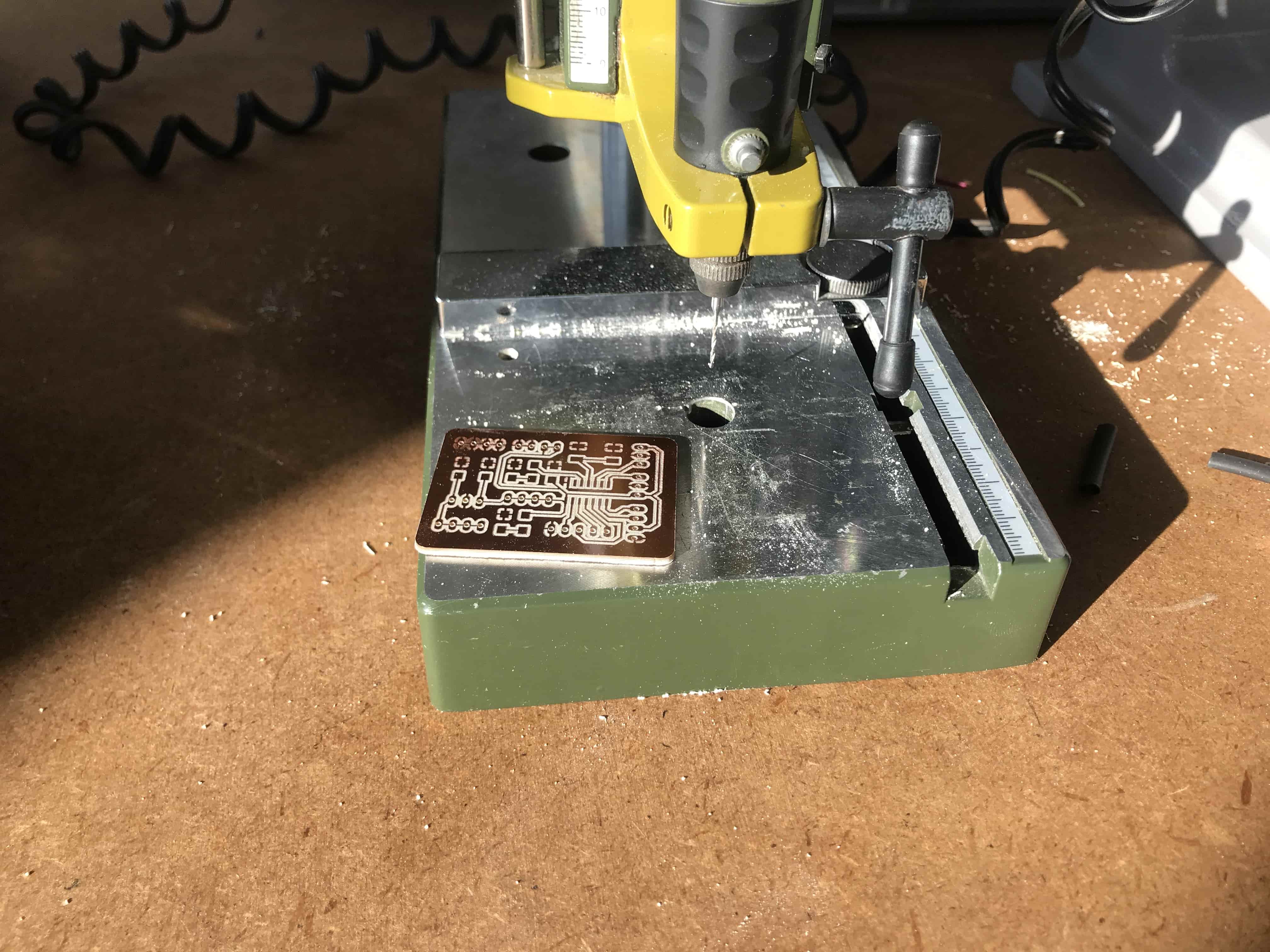
Follow these steps to mill your PCB:- Prepare the files as described above
- Change to the right end mill & collet (0,2mm end mill & 3,175 collet for traces)
- Power on the CNC (Roland MDX-40) and start Roland VPanel program on the laptop (Care: The lid of the CNC has to be closed for VPanel to be able to initialize!)
- Tape the copper plate to the CNC board with double sided tape
- Set the x,y,z origin: Move the spindel to the correct place using VPanel. As soon as x and y are alright, start the spindel at maximum speed and slowly move down, until you see and hear it cutting the plate slightly (Attention: The origin of the CNC is in the lower left corner, not in the upper)
- As soon as you find it, apply the x,y,z coordinates
- I copied my files on a USB stick. In the VPanel I chose cut, deleted other remaining files, chose add, chose the file, and chose output to cut
Cutout/Holes:
- Change to the right end mill & collet (1,0mm end mill & 3,175 collet for cutout/holes)
- Retake the Z origin, but watch out: The x an y have to stay the same!
- Launch the cutout file the same way as described above
For the holes I used a mulit-purpose tool (dremel). I wanted to work with another tool after being on the CNC for so long. Not having to prepare the file also saved me some time.
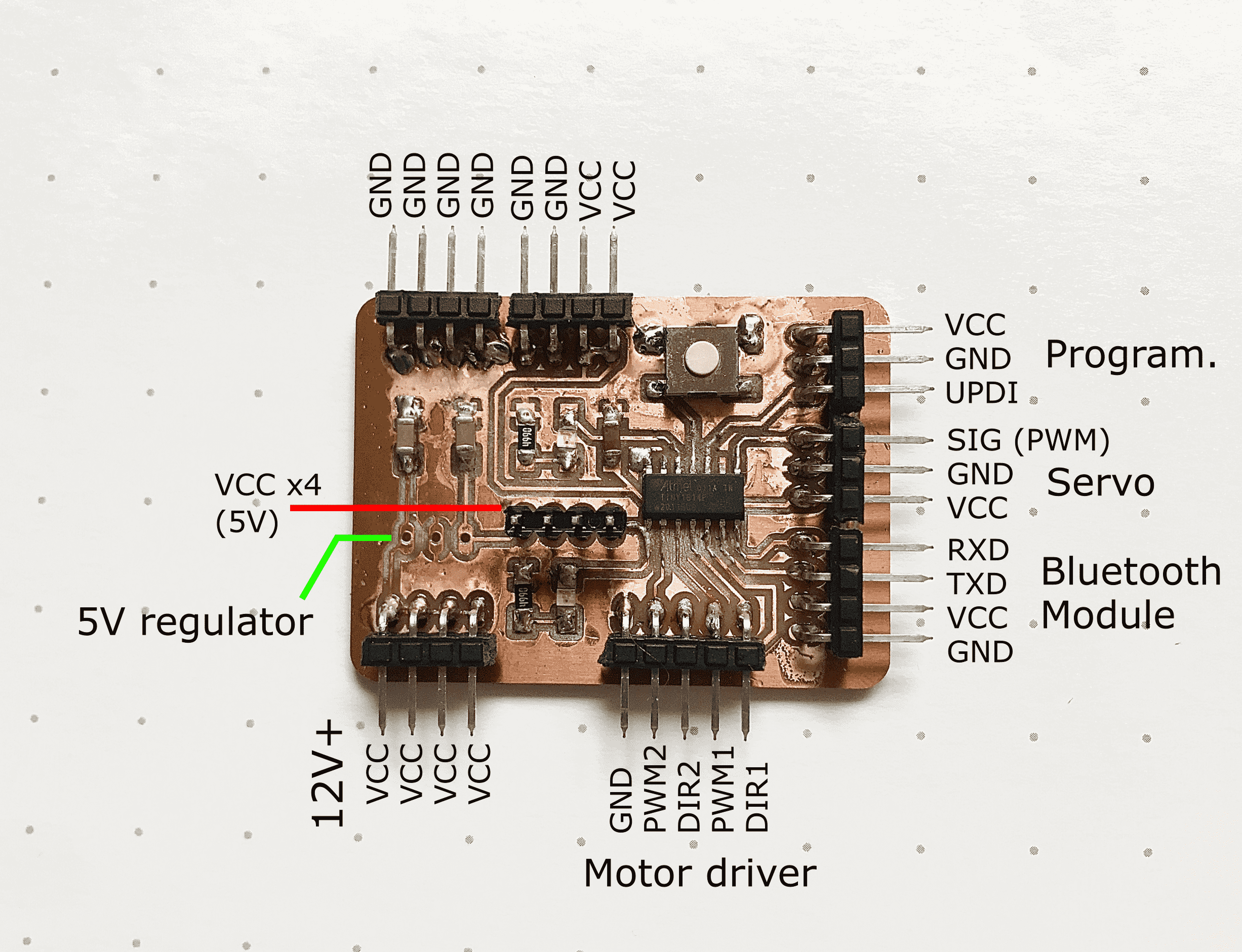
- Servo (Signal, GND, VCC)
- Bluetooth Module (RXD, TXD, VCC, GND)
- Motor driver (CYTRON Dual Channel 10A DC) (GND, PWM1, Dir1, PWM2, Dir2)
The board also includes a programmable button, an LED that turn on on receiving power and one LED to program (plus the needed capacitors and resistors).