Embedded Programming
Use your programmer to program your board to do something
Group assignment:
Group assignment
To compare the performance for different architectures we chose the following microcontrollers
(click on their names to view their tests):
Uwe:
ESP32-C3, ATTINY3216 and UNO R3 (ATmega328P).
Dorian:
XIAO ESP32C3, XIAO SAMD21, Arduino UNO and XIAO RP2040
Me: XIAO SAMD21
My part:
I used the following code from Neil Gershenfeld.
The code calculates (in 100000 iterations) the number
π and measure the time needed for that operation, as well as the number of millions of floating
point operations per second (MFLOPS).
MFLOPS measures the performance of the computer system to execute floating-point operations such
as add,
subtract, multiply and so on. MFLOPS refers to the total number of floating-point operations
executed (in millions) per second.
The lower the time the better and the bigger the MFLOPS the better.
/*
* pi.ino
* Neil Gershenfeld 12/20/20
* pi calculation benchmark
* pi = 3.14159265358979323846
*/

#define NPTS 100000

float a,b,c,pi,dt,mflops;
unsigned long i,tstart,tend;

void setup() {
	Serial.begin(115200);
	}

void loop() {
	tstart = millis();
	a = 0.5;
	b = 0.75;
	c = 0.25;
	pi = 0;
	for (i = 1; i <= NPTS; ++i)
		pi += a/((i-b)*(i-c));
	tend = millis();
	dt = (tend-tstart)/1000.0;
	mflops = NPTS*5.0/(dt*1e6);
	Serial.print("NPTS = ");
	Serial.print(NPTS);
	Serial.print(" pi = ");
	Serial.println(pi);
	Serial.print("time = ");
	Serial.print(dt);
	Serial.print(" estimated MFlops = ");
	Serial.println(mflops);
}
ATSAMD21G18A (Seeduino XIAO SAMD21)
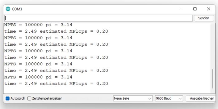
| Microcontroller / Board | Time (sec) | MFLOPS |
|---|---|---|
| ATSAMD21G18A / XIAO SAMD21 | 2.49 | 0.2 |
Seeduino XIAO SAMD21 documentation
The manufacturer has an elaborate documentation about the Seeduino XIAO SAMD21. Here's the important informations needed to start programming it:
Board features
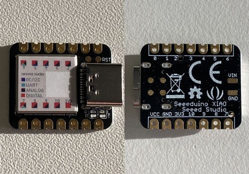
I am using the Seeed Studio XIAO SAMD21. It carries the ATSAMD21G18A-MU which is a low-power
microcontroller.
It's documentation describes it as having good performance in processing while not needing a lot
of power.
It's designed to be small and can be used for wearable devices and small projects.
Documentations I used for this page: Seedstudio (official) | Dronebotworkshop
All pins except Pin 0 support PWM.
For general I/O pins: Working voltage of MC is 3.3V. Voltage input connected to general I/O pins may cause chip damage if its higher than 3.3V. For power supply pins: The built-in DC-DC converter circuit is able to change 5V voltage into 3.3V and allows to power the device with a 5V supply via VIN-PIN and 5V-PIN. Please pay attention, do not lift the shield cover.
- Powerful CPU: ARM® Cortex®-M0+ 32bit 48MHz microcontroller(SAMD21G18) with 256KB Flash,32KB SRAM.
- Compatible with Arduino IDE.
- Easy project operation: Breadboard-friendly.
- Small size: As small as a thumb(20x17.5mm) for wearable devices and small projects.
- Multiple development interfaces: 11 digital/analog pins, 10 PWM Pins, 1 DAC output, 1 SWD Bonding pad interface, 1 I2C interface, 1 UART interface, 1 SPI interface.
| Item | Value |
|---|---|
| CPU | ARM Cortex-M0+ CPU(SAMD21G18) running at up to 48MHz |
| Flash Memory | 256KB |
| SRAM | 32KB |
| Digital I/O Pins | 11 |
| Analog I/O Pins | 11 |
| I2C interface | 1 |
| SPI interface | 1 |
| QTouch | 7 (A0,A1,A6,A7,A8,A9,A10) |
| UART interface | 1 |
| Power supply and downloading interface | Type-C |
| Power | 3.3V/5V DC |
| Dimensions | 20x17.5x3.5mm |
Pinout diagram: 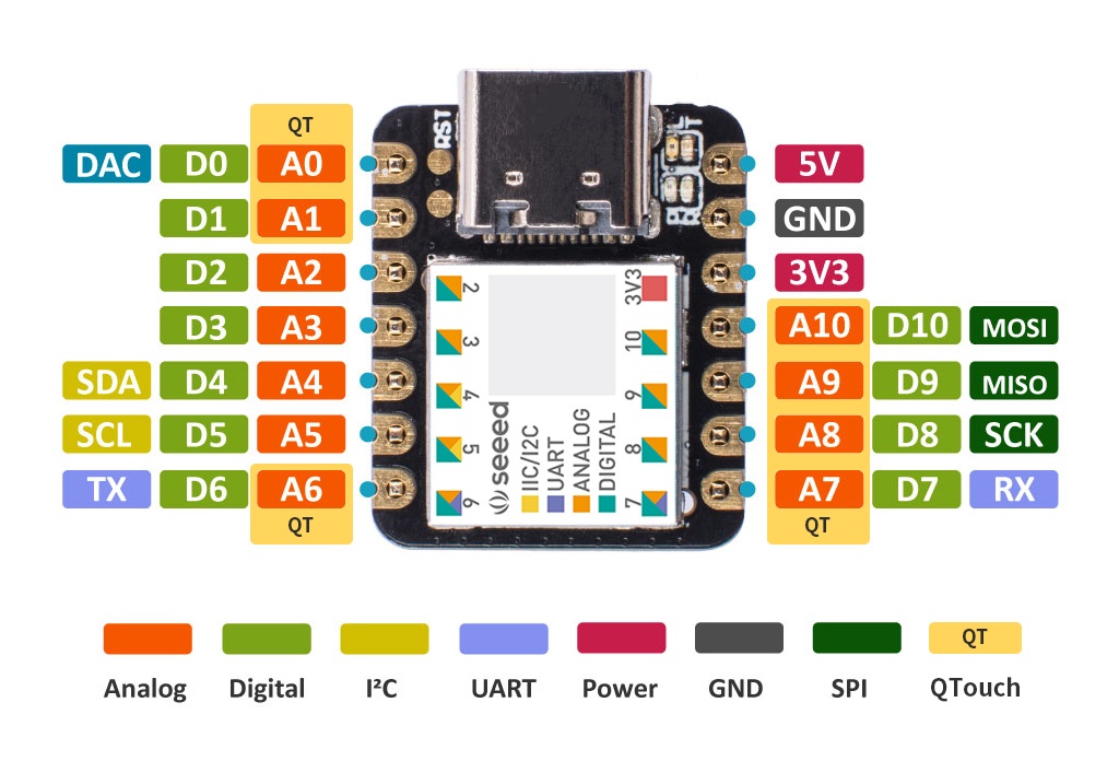
Setting up Arduino IDE for the board
.jpg) Download and launch the
Arduino IDE
Download and launch the
Arduino IDE.jpg) Click on File
> Preference, and fill Additional Boards Manager URLs with this URL:
https://files.seeedstudio.com/arduino/
package_seeeduino_boards_index.json
Click on File
> Preference, and fill Additional Boards Manager URLs with this URL:
https://files.seeedstudio.com/arduino/
package_seeeduino_boards_index.json.jpg) Click Tools->
Board-> Boards Manager..., print keyword "Seeed Xiao SAMD" in the searching blank. Here
comes the "Seeed SAMD Boards". Install it.
Click Tools->
Board-> Boards Manager..., print keyword "Seeed Xiao SAMD" in the searching blank. Here
comes the "Seeed SAMD Boards". Install it..jpg) After
installing the board, click Tools-> Board, find "Seeeduino XIAO" and select it. Now you
have already set up the board of Seeed Studio XIAO SAMD21 for Arduino IDE.
After
installing the board, click Tools-> Board, find "Seeeduino XIAO" and select it. Now you
have already set up the board of Seeed Studio XIAO SAMD21 for Arduino IDE..jpg) Select Tools
> Port. This is likely to be COM3 or higher (COM1 and COM2 are usually reserved for
hardware serial ports). To find out, you can disconnect your Arduino board and re-open
the menu; the entry that disappears should be the Arduino board. Reconnect the board and
select that serial port.
Select Tools
> Port. This is likely to be COM3 or higher (COM1 and COM2 are usually reserved for
hardware serial ports). To find out, you can disconnect your Arduino board and re-open
the menu; the entry that disappears should be the Arduino board. Reconnect the board and
select that serial port..jpg) Now write any
program (or choose from the examples), connect the board via USB-C to your PC and click
the "Upload" button in the environment.
Now write any
program (or choose from the examples), connect the board via USB-C to your PC and click
the "Upload" button in the environment.
Programming the board
I will try to program one input and one output device related to my final project: HC-SR04 Ultrasonic distance sensor and (Waterpump) Kamoer NKP-DC-S10Y.Input device: HC-SR04
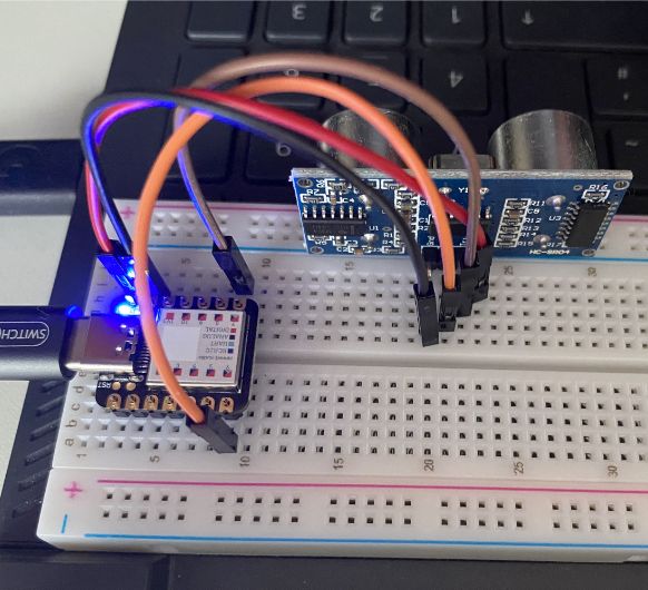
I need an HC-SR04 Ultrasonic sensor for my final project. It will detect the height of the water level in my watertank and in my flowerpot.
The HC-SR04 has 4 pins: VCC (normally 5V, but works with 3.3V), Trigger, Echo and GND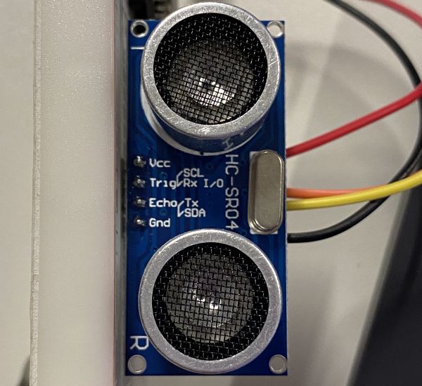
The TRIG pin and the ECHO pin have to be connected to any digital input pins on the board. For
example pin 6 and 7, or pin 9 and 10 (I need two HC-SR 04 later, so I tested for two)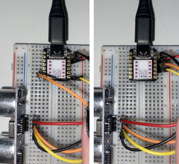
The HC-SR04 ultrasonic sensor sends out a pulse of sound waves and measures the time it takes for the waves to bounce back off an object and return to the sensor. The duration variable in the code represents the time it takes for the sound waves to travel to the object and back, in units of microseconds.
To convert the time duration into a distance measurement in centimeters and inches, we need to use the speed of sound in air. Sound travels through air at a speed of approximately 343 meters per second (or about 0.0343 centimeters per microsecond). However, the sound wave has to travel twice the distance (to the object and back), so we divide the duration by 2 to get the one-way distance in centimeters. Therefore, in the code, we divide the duration by 2 and then multiply by the speed of sound in air (0.0343 cm/uS) to get the distance in centimeters.
/*
* created by Rui Santos, https://randomnerdtutorials.com
*
* Complete Guide for Ultrasonic Sensor HC-SR04
*
Ultrasonic sensor Pins:
VCC: +5VDC
Trig : Trigger (INPUT) - Any digital pin
Echo: Echo (OUTPUT) - PAny digital pin
GND: GND
*/

int trigPin = 6;    // Trigger
int echoPin = 7;    // Echo
long duration, cm, inches;

void setup() {
	//Serial Port begin
	Serial.begin (9600);
	//Define inputs and outputs
	pinMode(trigPin, OUTPUT);
	pinMode(echoPin, INPUT);
}

void loop() {
	// The sensor is triggered by a HIGH pulse of 10 or more microseconds.
	// Give a short LOW pulse beforehand to ensure a clean HIGH pulse:
	digitalWrite(trigPin, LOW);
	delayMicroseconds(5);
	digitalWrite(trigPin, HIGH);
	delayMicroseconds(10);
	digitalWrite(trigPin, LOW);

	// Read the signal from the sensor: HIGH pulse (duration of the time (in microseconds)
	// from sending of the ping to reception of its echo off of an object.)
	pinMode(echoPin, INPUT);
	duration = pulseIn(echoPin, HIGH);//Reads a pulse (either HIGH or LOW) on a pin.
					//For example, if value is HIGH, pulseIn() waits
					//for the pin to go from LOW to HIGH, starts timing,
					//then waits for the pin to go LOW and stops timing.

	// Convert the time into a distance
	cm = (duration/2) / 29.1;     // Divide by 29.1 or multiply by 0.0343 (The speed of sound is: 343m/s = 0.0343 cm/uS = 1/29.1 cm/uS)
	inches = (duration/2) / 74;   // Divide by 74 or multiply by 0.0135

	Serial.print(inches);
	Serial.print("in, ");
	Serial.print(cm);
	Serial.print("cm");
	Serial.println();

	delay(250);
}
The working sensor (While I move my hand closer and further away from the sensor,
the different distances are displayed on the serial monitor):
Output device: (Waterpump) Kamoer NKP-DC-S10Y
I am using the waterpump as my output device this week. It is a 12V pump and needs an external
powersupply as well as a MOSFET to control it.
MOSFETs (Metal-Oxide-Semiconductor Field-Effect Transistor) are commonly used as a switch or an
amplifier.
They have three terminals: the source, the gate, and the drain, and their conductive behavior is
controlled by the voltage applied to the gate.
This is my connection schema:
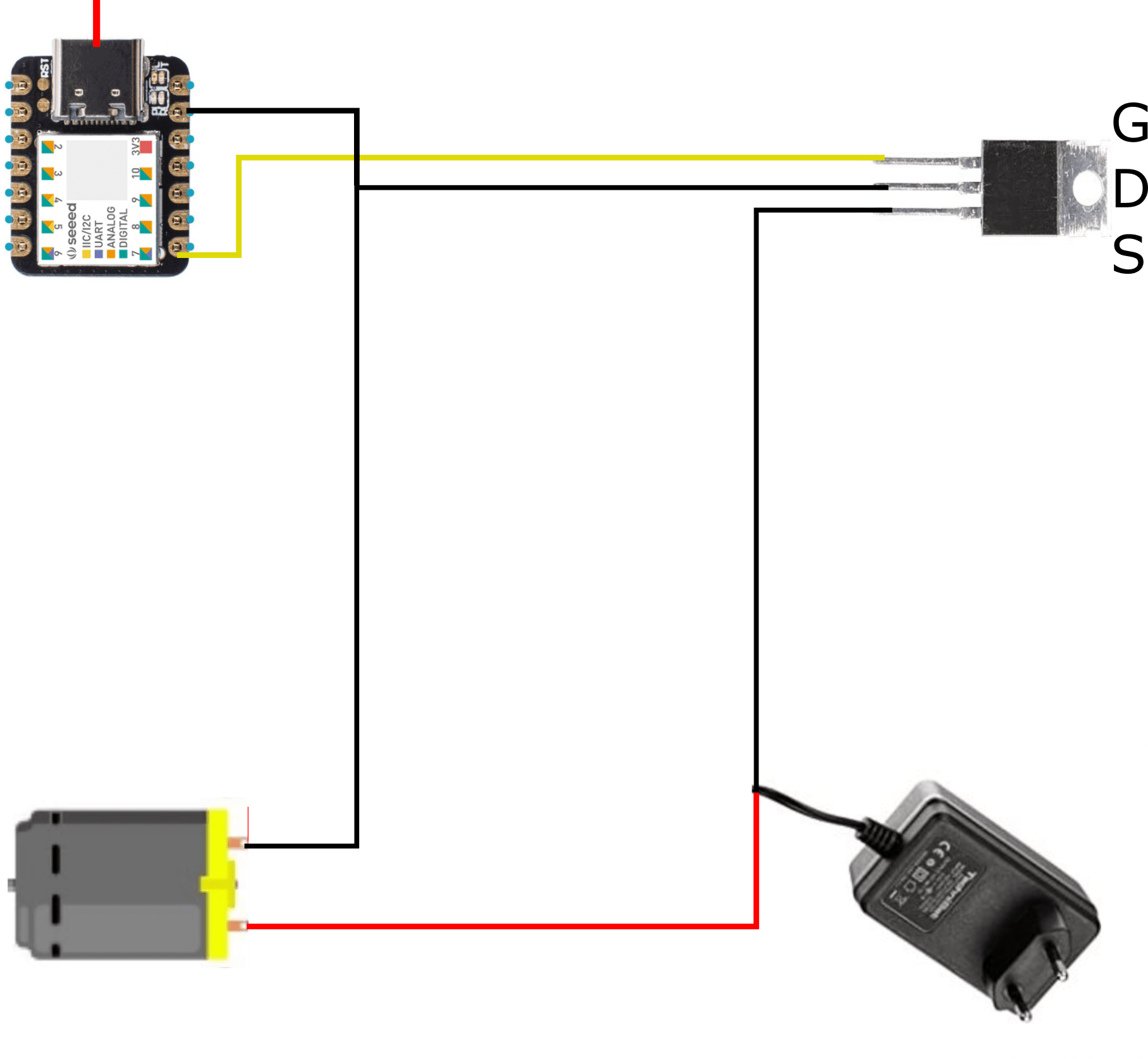 I am connecting the Gate of the MOSFET to Pin 7 of my
microcontroller. An external 12V powersupply is utilized which I plug into a power outlet.
The GND of the power supply is connected to the Source of the MOSFET.
The VCC of the power supply is connected to the VCC of the pump. GND of the pump is connected to
the Drain.
I am connecting the Gate of the MOSFET to Pin 7 of my
microcontroller. An external 12V powersupply is utilized which I plug into a power outlet.
The GND of the power supply is connected to the Source of the MOSFET.
The VCC of the power supply is connected to the VCC of the pump. GND of the pump is connected to
the Drain.
Like this, there's a gap in the circuit connecting the pump with the power. This gap is bridged
if power is applied to the Gate, which is connected to and therefore controlled by the
microcontroller.
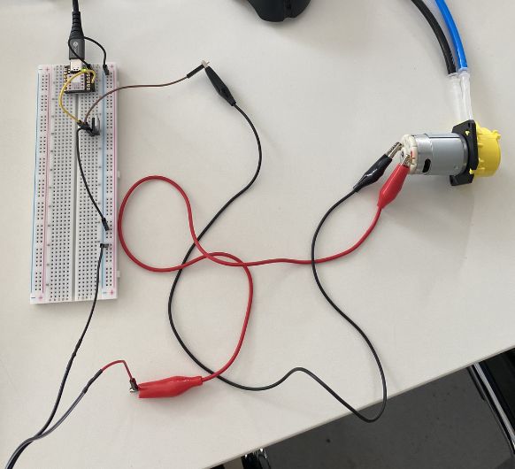 Connection on the
breadboard
Connection on the
breadboard 12V power supply
The following code is the one I used to operate the pump. To save a few minutes and to test it's capabilities I used ChatGPT to generate it. Essentially, it is very easy though: The pin 9, which the gate of the MOSFET is connected to, is set as an output pin. Inside the loop, power gets supplied to this pin for 1 second, and then the power supply is stopped for 1 second. This let's the pump run every 1 second for 1 second.
						// Define the MOSFET pin
const int MOSFET_PIN = 9;

void setup() {
  // Set the MOSFET pin as an output
  pinMode(MOSFET_PIN, OUTPUT);
}

void loop() {
  // Turn the MOSFET on
  digitalWrite(MOSFET_PIN, HIGH);

  // Wait for a short period of time
  delay(1000);

  // Turn the MOSFET off
  digitalWrite(MOSFET_PIN, LOW);

  // Wait for a short period of time
  delay(1000);
}
The working pump: