Embedded Programming
Group assignment:
- Compare the performance and development workflows for other architectures
- Document your work on the group work page and reflect on your individual page what you learned
Individual assignment:
- Browse through the datasheet for your microcontroller
- Program a microcontroller development board to interact and communicate
Spiral goals
- Configure Raspberry Pico, XIAO ESP32-C3, and XIAO SAMD21 to Arduino IDE and do a performance benchmark (Group Assignment)
- Read the datasheet of the Seeed XIAO SAM21 (Assignment)
- Talk to the board with Serial command (Assignment)
- Change an RGB LED color from an analog joystick (Assignment**)
- Try a different Board, like ESP32C3 (Assignment)
- Try to run another programming language on one of the boards (Bonus)
- Read More datasheets like for RP2040 or ESP32-C3. (Bonus)
- Connect an LCD screen on the board (Bonus)
- Try to use a different IDE, like PlatformIO (Bonus)
Some benchmarks
Configure Arduino IDE to my boards
To let Arduino IDE talk to my boards, I need to add them with a board manager. For that, you can add some Board manager URLs in the Preferences panel.
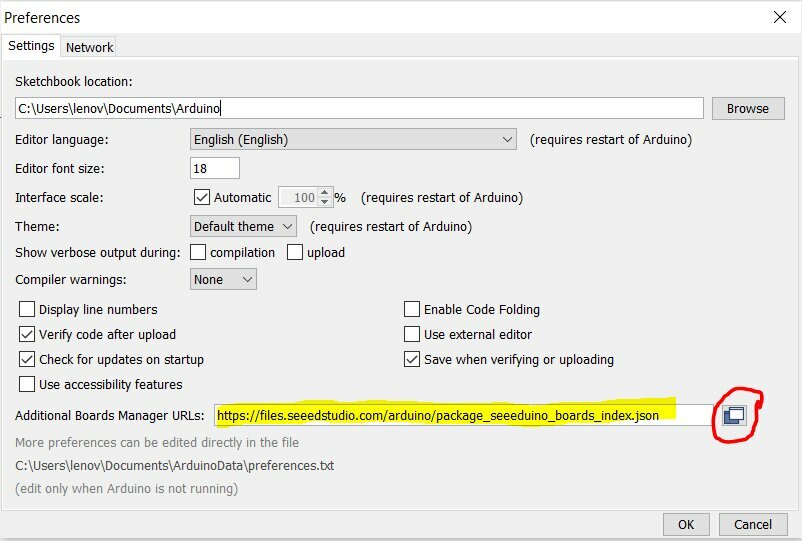
I find the URLs for the SAMD21 here, for the ESP32C3 here, and for the Raspberry Pico here (RP2040).
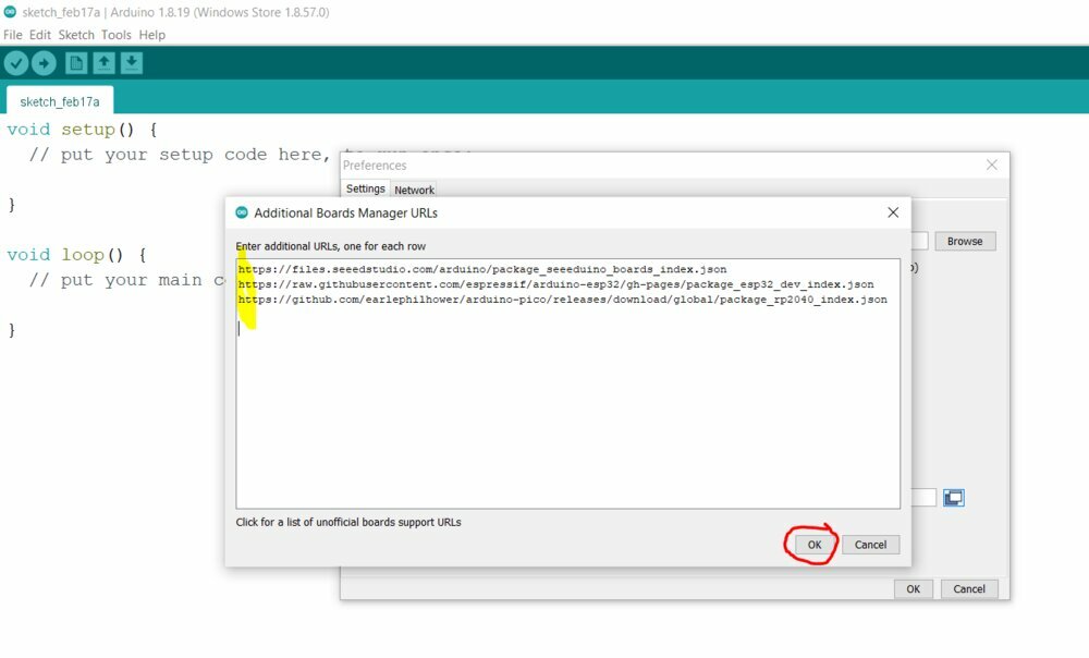
Then you go to Tool > Board: > Boards Manager.... Using the search function, I looked for my boards and installed them.

Run a pi calculator
So first I run a PI decimal calculator. With this code from Neil Gershendeld:
/*
* pi.ino
* Neil Gershenfeld 12/20/20
* pi calculation benchmark
* pi = 3.14159265358979323846
*/

#define NPTS 100000

float a,b,c,pi,dt,mflops;
unsigned long i,tstart,tend;

void setup() {
   Serial.begin(115200);
   }

void loop() {
   tstart = millis();
   a = 0.5;
   b = 0.75;
   c = 0.25;
   pi = 0;
   for (i = 1; i <= NPTS; ++i)
      pi += a/((i-b)*(i-c));
   tend = millis();
   dt = (tend-tstart)/1000.0;
   mflops = NPTS*5.0/(dt*1e6);
   Serial.print("NPTS = ");
   Serial.print(NPTS);
   Serial.print(" pi = ");
   Serial.println(pi);
   Serial.print("time = ");
   Serial.print(dt);
   Serial.print(" estimated MFlops = ");
   Serial.println(mflops);
}
What it means, it's a simple code to calculate in 100000 iterations (NPTS in the code) the number and measure the time for that operation and the number of floating point operations per second (MFlops).
When I try to run this code, my Raspberry Pico didn't start or turn on at all. I also try to connect my Seeed XIAO RP2040 but it wasn't detected by the Arduino IDE. So I decided to replace it with an old Arduino Uno (ATEMGA328P) I have. When you download the code on the board, you can open de Serial Monitor (on the top-right of the IDE window). I change the baud rates to 115200 as the code on the bottom-right of the serial monitor.
Here are the results from this test EDIT: I succeed to run the XIAO RP2040 so I added the result here.
| Board | Time(sec) | MFlops |
|---|---|---|
| XIAO ESP32C3 | 0.42 | 1.19 |
| XIAO SAMD21 | 2.49 | 0.20 |
| Arduino UNO | 6.65 | 0.08 |
| XIAO RP2040 | 0.35 | 1.44 |
The lowest time the better and the biggest MFlops the better. My 10-year-old Arduino looks pretty weak in comparison to the new ESP32C3 (Risk-V). Finally, it's the RP2040 that runs the best.
Microcontroller I/O & ADC Benchmarks
Another test is the speed to write or read on the digital or analog pin of the board. Using this Arduino code from a member of the Arduino's forum. I run it on the tree boards. The test tries to write or read over 50000 iterations and does a time average for one read/write operation (in milliseconds).
Here is a chart that compiles all the results (+ XIAO RP2040).
As we can see, for digital read and write, the ESP32C3 and the RP2040 are the faster by far (10 times faster than the Arduino UNO). The Digital Read is so quick, we can see it on the diagram (respectively, and ) But surprisly, for Analog read, the SAMD21 is better than the ESP32C3.
Let read some docs
Let's dive into the documentation of the Seeed XIAIO SAMD21. The manufacturer has a nice wiki about the board.
Specifications
First here the specification of the board:
| Item | Value |
|---|---|
| CPU | ARM Cortex-M0+ CPU(SAMD21G18) running at up to 48MHz |
| Flash Memory | 256KB |
| SRAM | 32KB |
| Digital I/O Pins | 11 |
| Analog I/O Pins | 11 |
| I2C interface | 1 |
| SPI interface | 1 |
| QTouch | 7 (A0,A1,A6,A7,A8,A9,A10) |
| UART interface | 1 |
| Power supply and downloading interface | Type-C |
| Power | 3.3V/5V DC |
| Dimensions | 20×17.5×3.5mm |
Pins overview of the board
Here an overview of all the pins of the board. It's a pretty small form factor for a development board.
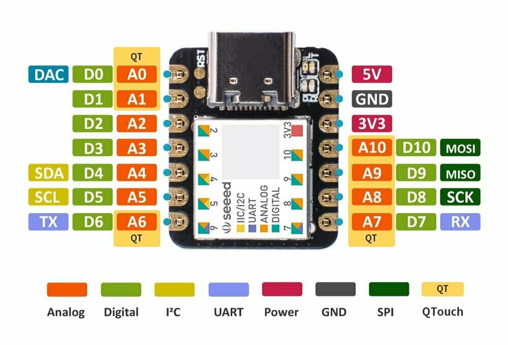
source seeedstudio.com
We can see the pins with communication protocols (I²C, UART and SPI), QTouch (Peripheral Touch Controller), Digital I/O and Analag I/O.
The actual Datasheet
Indisde of the XIAO SAMD21 there is a SAMD21G18 microcontroller design buy Atmel (now Microchip). I downloaded the datasheet from this page.
Chapter 1 - Description
A "Brief" description of what SMAD21 can do.
Chapter 2 - Configuration Summary
You can fin a summary of the capacity of the microcontroller.
| Items | SAM D21G |
|---|---|
| Pins | 48 |
| General Purpose I/O-pins (GPIOs) | 38 |
| Flash | 256/128/64/32KB |
| SRAM | 32/16/8/4KB |
| Timer Counter (TC) instances | 3 |
| Waveform output channels per TC instance | 2 |
| Timer Counter for Control (TCC) instances | 3 |
| Waveforms output channels per TCC | 8/4/2 |
| DMA | channels |
| USB | interface |
| Serial Communication Interface (SERCOM) instances | 6 |
| Inter-IC | Sound |
| Analog-to-Digital Converter (ADC) channels | 14 |
| Analog Comparators (AC) | 2 |
| Digital-to-Analog Converter (DAC) channels | 1 |
| Real-Time | Counter |
| RTC alarms | 1 |
| RTC compare values | One 32-bit value or two 16-bit values |
| External Interrupt lines | 16 |
| Peripheral Touch Controller (PTC) X and Y lines | 12x10 |
| Maximum CPU frequency | 48MHz |
Chapter 3 - Ordering the Information
Here we can learn about the meaning of the SMAD 21 G 18.
- Product Family SAMD = General Purpose Microcontroller
- Product Series 21 = Cortex M0 + CPU, Basic Feature Set + DMA + USB
- Pin Count G = 48 Pins
- Flash Memory Density 18 = 256Kb
More letters can be added about variants or packages.
Chapter 4 - Block Diagram
Here is the block diagram of it:
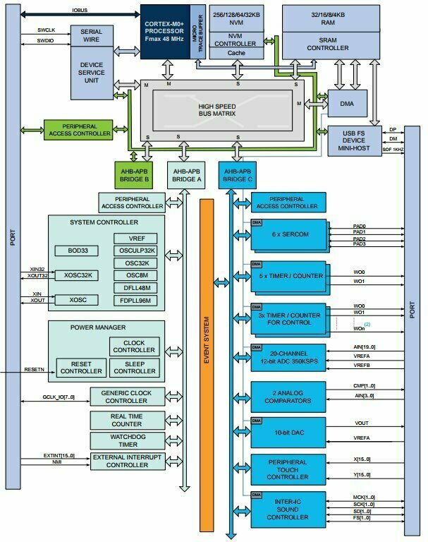
We can see the Cortex-M0, it's the ARM Processor. It talks to the RAM and SRAM mermories to store the results of its operations. Trought a High Speed Bus Matrix it is connected to different modules. Here are some I recognized.
On top of the diagame there is the NVM, it is about non-folatile memory, where you store the data you want to keep when the microcontroller is turned off.
On the left, there somes controllers. Like the System Controller. It has different modules, like VREF (Voltage Reference) that give a stable voltage for the analog input/output.
In the Power Manager you can find a Real Time Counter a digital clock that keep track of time when there is no/low power. Or some other module that seems to put the microcontroller in sleep mode or able to reset it.
On the right side It's most of the peripherals. Like SERCOM (Communication ports: I²C, Serial, UART, TX, ...), ADC (Analog to Digital), Analog comparators, DAC (Digital to Analog), Touch Controller (the Qtouch on the Overview).
I still don't know what is inside all those blocks, I hope to find out on the way.
Chapter 5 - Pinout
Here I found the different Pins that go out of the microcontroller.

I can already see some Pins I can find on the XIAO board.
Chapter 6 - Signal Description List
Here is an important chapter. Regarding the paripherals in the Block Diagram, it gives a list of the signals that go trought them. There are clasified by type (Analog, Digital, Input and/or Output).
There I see the PWM outputs (was the Timer counter in the Diagram). This can be used to create a digital potentiometer for example.
Chapter 7 - I/O Multiplexing and Considerations
This I didn't get it
Chapter 8 - Power Supply and Start-Up Considerations
Some considerations about the power supply of the microcontroller.
Chapter 9 - Product Mapping
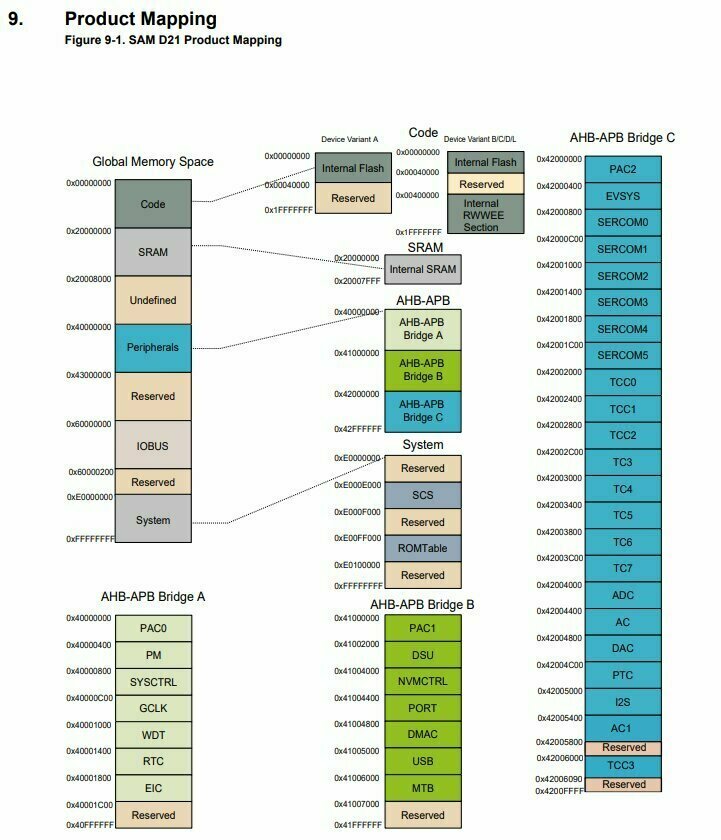
It looks like memory addresses, I guess to reach some ports or functions of the microcontroller.
Chapter 10 - Memories
About the memores of the microcontroller and how to reach them (address).
Here for example the Physical Memory Map.
| Mermory | Start Address | SAMD21x18 |
|---|---|---|
| Internal Flash | 0x00000000 | 256 Kbytes |
| Internal RWWEE Emulation section(2) | 0x00400000 | - |
| Internal SRAM | 0x20000000 | 32 Kbytes |
| Peripheral Bridge A | 0x40000000 | 64 Kbytes |
| Peripheral Bridge B | 0x41000000 | 64 Kbytes |
| Peripheral Bridge C | 0x42000000 | 64 Kbytes |
| IOBUS | 0x60000000 | 0.5 Kbytes |
If I understood, the High-Speed Bus (cfr. block Diagram) have fixed addresses that can't be changed. From there you can reach different memories (RAM, SRAM, NVM, etc.).
Chapter 11 to 48
I'm only at 5% of the datasheet, and my brain is hurting a bit. I stop for now and I'll go back later on it for specific needs.
Let's interact with the SAMD21
At the Local lecture, I followed Ahmed's tutorial (the Kamp-Lintfort's instructor) "in live" and was able to blink the internal led of the board and receive some Serial print. Here the file.
Blink a RGB LED
Let's add some colors. Have some prototype components, one of them is an RGB LED, capable to change color. It already has the resistors included to receive the right amount of current. Most LEDs accept , so if we don't want to damage them, we need to add a resistor in series. To find out which one, we need to follow the Ohm Law.
So here is the resistor we need . As I said, my RGB LED module has already the resistors.

I found this schema to see how to connect an RGB LCD to a microcontroller board. I follow more or less this tutorial, but write my variables and try some C++ stuff.
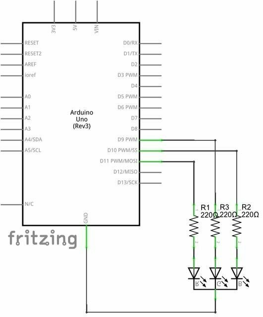
source carnetdumaker.net
So I need 3 PWW Pins (so we will be able to fade the LED). In the second paragraph of the Seeed Studio Wiki they say that the pins D1 to D10 are PWM interfaces. I chose Pin D1 for the Red, D2 for the Green, and D3 for the Blue of my LED and I connected the Ground pin of the LED to the Ground of the board (Nicely, I found the appropriate color for the Dupont wires).
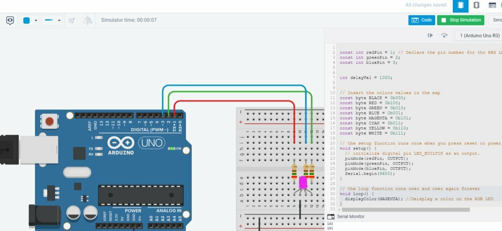
It's cool, but I need to write the code to make it work. For security, I switched to Tinkercad to test it in virtual before implated on the board.
I started with a copy of the Blink.ino programm. So first I declared all the Pins I will use.
const int redPin = 1; // Declare the pin number for the RBG LED
const int greenPin = 2;
const int bluePin = 3;

int delayVal = 1000;

// the setup function runs once when you press reset or power the board
void setup() {
  // initialize digital pins as an output.
  pinMode(redPin, OUTPUT);
  pinMode(greenPin, OUTPUT);
  pinMode(bluePin, OUTPUT);
  Serial.begin(9600);
}
An RGB LED is like 3 different LEDs of Red, Green, and Blue. With 2 states possible: on (1) or off (0), we have 8 possibilities. In binary it can be written like this:
RGB
000 // BLACK
100 // RED
010 // GREEN
001 // BLUE
101 // MAGENTA
011 // CYAN
110 // YELLOW
111 // WHITE
With C/C++ language we can use the 0bXXX to declare binary numbers.
I'll store this data in keys-values in map build with Map Classe. That will allow me to reach them easily. TinkerCAD doesn't allow you to install custom libraries, so I switched back to Arduino IDE.
First I needed to add the STL library (Sketch > Includes Library > manage Libraries ...). I searched for the ArduinoSTL by Mike Matera and installed it.
#include <ArduinoSTL.h>
#include <iostream>
#include <map>
// Create a map of strings to bytes
std::map<std::string, byte> colors;

// Insert the colors values in the map
colors["black"] = 0b000;
colors["red"] = 0b100;
colors["greeb"] = 0b010;
colors["blue"] = 0b001;
colors["magenta"] = 0b101;
colors["cyan"] = 0b011;
colors["yellow"] = 0b110;
colors["white"] = 0b111;
Tried to compile it, but it didn't work. And it seems that the library ArduinoSTL may not be compatible to the SAMD architecture. So I'll switch back to normal variables for now. It means I can go back to TinkerCAD too.
// Colors in byte format
const byte BLACK = 0b000;
const byte RED = 0b100;
const byte GREEN = 0b010;
const byte BLUE = 0b001;
const byte MAGENTA = 0b101;
const byte CYAN = 0b011;
const byte YELLOW = 0b110;
const byte WHITE = 0b111;
Now we can create a function that will display a color. The RGB LED on Tinker and my RGB LED are *common cathode RGB LED". I just need to apply a HIGH signal (= 1) on the appropriate LEDpin.
void displayColor(byte color) {
  // Read the appropriate bit from the byte
  digitalWrite(redPin, bitRead(color, 2));
  digitalWrite(greenPin, bitRead(color, 1));
  digitalWrite(bluePin, bitRead(color, 0));
}
So let's try to light the RGB LED with MEGENTA (= Red + Blue).
// the loop function runs over and over again forever
void loop() {
  displayColor(MAGENTA); //Display a color on the RGB LED
}
Here we go.
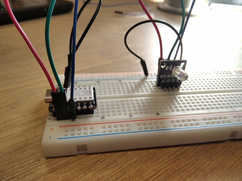
And a CYAN (Green + Blue) on the actual board.
Choose the color I want
With the USB serial port, I can talk to the SMAD21. So let's implement a way to select the color I want. So I need to read the Serial. For that, I read this article](https://www.norwegiancreations.com/2017/12/arduino-tutorial-serial-inputs/#:~:text=To%20send%20characters%20over%20serial,on%20your%20keyboard%20to%20send.). And change my code like this:
// the loop function runs over and over again forever
void loop() {
  // If the are some bytes of data which have arrived in the serial buffer
   if(Serial.available()){
      // combine all the characters in the sent message into a single Arduino string until the /n charactec (end of the line) and put in the the command variable.
       command = Serial.readStringUntil('\n');
       Serial.print("You typed: " );
       Serial.println(command); // Print the command
   }
}
I will need a variable to store the command string and the currentColor byte.
// Input variable
String command;

// store the current color
byte currentColor;
Now that's done, I created a new function to retrieve the right color variable from the command.
// function that return the right color byte
void commandToColorByte(String command) {

  if(command.equals("black")){
    currentColor = BLACK;
  }
  else if(command.equals("red")){
    currentColor = RED;
  }
  else if(command.equals("green")){
    currentColor = GREEN;
  }
  else if(command.equals("blue")){
    currentColor = BLUE;
  }
  else if(command.equals("magenta")){
    currentColor = MAGENTA;
  }
  else if(command.equals("cyan")){
    currentColor = CYAN;
  }
  else if(command.equals("yellow")){
    currentColor = YELLOW;
  }
  else if(command.equals("white")){
    currentColor = WHITE;
  }
  else{
      Serial.println("Invalid command");
      Serial.println("You need to choose between those colors:");
      Serial.println("black");
      Serial.println("red");
      Serial.println("green");
      Serial.println("blue");
      Serial.println("magenta");
      Serial.println("cyan");
      Serial.println("yellow");
      Serial.println("white");
  }
}
// the loop function runs over and over again forever
void loop() {
   if(Serial.available()){  // returns the bytes of data which have arrived in the serial buffer
       command = Serial.readStringUntil('\n'); // combine all the characters in the sent message into a single Arduino string until the /n charactec (end of the line).
       Serial.print("You typed: " );
       Serial.println(command);
       commandToColorByte(command); //store the right color in the currentColor variable
   }
   displayColor(currentColor); //display the current color
}
And it's working !
Switch to AnalogWrite
The Pins we use can output a PWM Signal that can be changed on an 8-bit scale (meaning varied by 256 steps)^[https://www.engineersgarage.com/articles-arduino-rgb-led-driver-analogwrite-pwm/]
Instead of digitalWrite, I'm using the analogWrite function.
void displayColor(byte r, byte g, byte b) {
  // Set the appropriate bit from the bytes
  analogWrite(redPin, r);
  analogWrite(greenPin, g);
  analogWrite(bluePin, b);
}
And I can now use it to apply a more complex color like the Arduino color.
// the loop function runs over and over again forever
void loop() {
   displayColor(0, 129, 132);
}
Let's play with an analog joystick
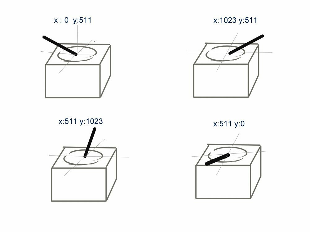
Using the analog PINs of the board it can do an ADC resolution of 12 bits (from 0 to 4095) or 10 bits^[https://wiki.seeedstudio.com/Seeeduino-XIAO/#analog-input-and-output]. On the Joystick, you have VRx and VRy that I plugged respectively into the A4 and A5 pins. On a 10 bits configuration, the Home value of the joystick is x=511, y=511.
 source exploreembedded.com
It can be plugged like this:

source exploreembedded.com
For Analog read on the XIAO SAMD21, we need to plug it to the 3,3Volt not the 5V. Like it said on the wiki
https://wiki.seeedstudio.com/Seeeduino-XIAO/#analog-input-and-output
First I define the PINs and the x/yValue and set up the analog resolution with analogReadResolution() function.
#define joyX A4
#define joyY A5

float xValue;
float yValue;
...

void setup()
{
  analogWriteResolution(10); // Set analog out resolution to max, 10-bits
  ...
}
Then I can read the value on the monitor function.
void loop() {
  // put your main code here, to run repeatedly:
  xValue = analogRead(joyX);
  yValue = analogRead(joyY);

  //print the values with to plot or view
  Serial.print(xValue);
  Serial.print("\t");
  Serial.println(yValue);
  delay(250);
}
Here we can see the value:
Remap the joystick to the RGB values
The idea is when moving the joystick, I will go to one of the three RGB colors. I did a "beautiful" draw in Inkscape to show the remap of the Joystick value to the Red, Green, and Blue. This code is mostly inspired by this code

So first we need to declare the color's positions and some variables to store the current Red, Green, and Blue values
// the position of the RGB colors
const int redX = 511;
const int redY = 1023;
const int greenX = 1023;
const int greenY = 0;
const int blueX = 0;
const int blueY = 0;

// Store the current RGB brightness
int brightRed;
int brightGreen;
int brightBlue;
Then I need a function to transform the joystick position to the appropriate color. I needed to change the X-axe orientation to match the orientation of my drawing.
void setColorsFromAxis(float xValue, float yValue) {
  // Flip orientation the X axe
  xValue = map(xValue, 0, 1023, 1023, 0);
  // Do the Pythagore geometry to get the distance between the color and the position of the joystick.
  int distanceRed = sqrt(pow(abs(redX - xValue), 2) +  pow(abs(redY - yValue), 2));
  int distanceGreen = sqrt(pow(abs(greenX - xValue), 2) +  pow(abs(greenY - yValue), 2));
  int distanceBlue = sqrt(pow(abs(blueX - xValue), 2) +  pow(abs(blueY - yValue), 2));

  // remap the distance on a 8 bit scale (0-255) and set the brighness of the colors
  brightRed = 255 - constrain(map(distanceRed, 0, 1023, 0, 255), 0, 255);
  brightGreen = 255 - constrain(map(distanceGreen, 0, 1023, 0, 255), 0, 255);
  brightBlue = 255 - constrain(map(distanceBlue, 0, 1023, 0, 255), 0, 255);
}
And it's working! =) (in OBS studio, I could overlay the axis remap on the video to have a better understanding).
Get the temperature and humidity from an ESP32C3
Let's try another board. I already installed in the Arduino IDE my ESP32C3 for the benchmark. Here is an overview of the Pins of the ESP32C3.
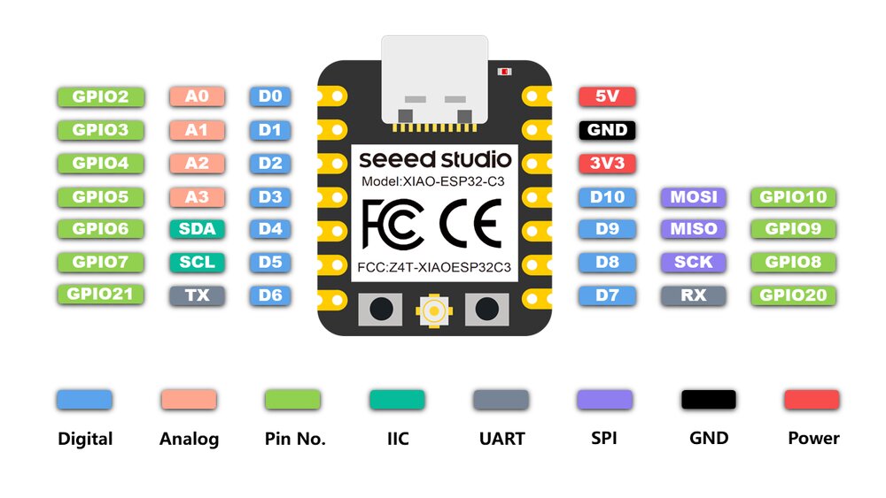 source wiki.seeedstudio.com
I have a temperature and humidity DHT11 sensor, following this tutorial I should be able to do something out of it.
DHT11 Datasheet
So first I looked for the DHT11 datasheet to understand the component.
Here are the specifications:
- Operating Voltage: 3.5V to 5.5V (1pin)
- Operating current: 0.3mA (measuring) 60uA (standby)
- Output: Serial data (2Pin)
- Temperature Range: 0°C to 50°C
- Humidity Range: 20% to 90%
- Resolution: Temperature and Humidity both are 16-bit (Serial Data)
- Accuracy: ±1°C and ±1%
Here is a connection diagram of the sensor to an MCU.
 source [components101.com](https://components101.com/sensors/dht11-temperature-sensor
As I have a DHT11 module and not just the sensor, the pull-up resistor is already build-in. The pull-up resistor is there to ensure that the voltage is well-defined even when there is no signal.^[https://en.wikipedia.org/wiki/Pull-up_resistor]
DHT11 module can differ, mine has a pin configuration like this:
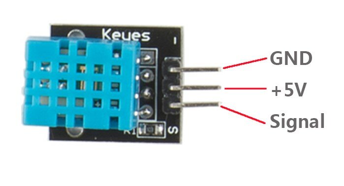 source learn.sunfounder.com
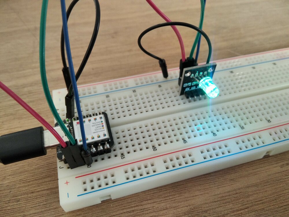
I connected the ground (GND) pins together, I chose a lower voltage of as the DHT11's datasheet said we can. And I connected the Signal to the D0 pin of the XIAO ESP32C3. To have something more portable I connected the pins with 3 female Dupont wires.

Read the serial data
The easiest way to read the data in the code is to use the Adafruit DHT sensor library. So I went to Sketch > Library > Manage Libraries... and searched for DHT sensor library by Adafruit. I said yes when it asked me to install also another dependency. Then I reuse the test code in the tutorial, and just change some parameters to match my configuration.
#include "DHT.h"
#define DHTPIN 0 // Digital pin connected to the DHT sensor
// Here I define my DHT sensor (I have a DHT11)
#define DHTTYPE DHT11 // DHT 11
DHT dht(DHTPIN, DHTTYPE);
void setup()
{
Serial.begin(9600);
Serial.println(F("DHT11 test"));
dht.begin();
delay(2000);
}
void loop()
{
float h = dht.readHumidity();
float t = dht.readTemperature();
// Check if any reads failed and exit early (to try again).
if (isnan(h) || isnan(t))
{
Serial.println(F("Failed to read from DHT sensor!"));
return;
}
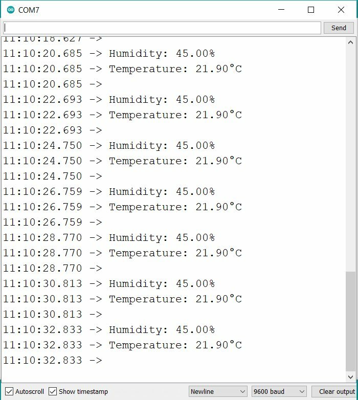
Serial.print(F("Humidity: "));
Serial.print(h);
Serial.println("%");
Serial.print(F("Temperature: "));
Serial.print(t);
Serial.println(F("°C "));
Serial.println("");
delay(2000);
}
And I push this code on the board. I needed to change the board and the port in the Arduino IDE first. (Tools > Board/Port).
I did an Upload to the board, and the code was sent, but it Failed to read from DHT sensor! So I try to define the pin DO instead of just 0, but then:
A fatal error occurred: No serial data received.
Looking at the troubleshooting Expressif's doc it seems that the board is no longer in download mode. So I went into boatloader mode following this command.
Leaving... Hard resetting via RTS pin... Is not an error, it just means that is gonna reset the board so it will start the program. If it doesn't work, you can push the reset button manually.^[https://electronicsinnovation.com/hard-resetting-via-rts-pin-fixed-explained/]
So I retried once more with a #define DHTPIN D0 for the pin. And now it's working!
Let's connect the ESP32 to the WIFI
Built-in RGB LED in XIAO RP2040
Using the Seeed wiki's tutorial, I also try the RGB Led on an XIAO RP2040 board. It shows a rainbow.
Connect to PlatformIO
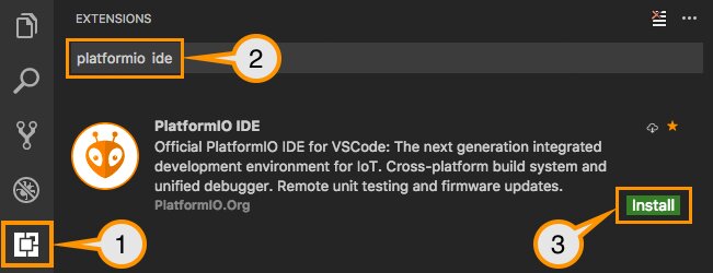
As I use VS Code to document my weekly assignments, I wanted to try to use PlatformIO as an embedded IDE. So first I add the extension. It will install the PlatformIO Core automatically.
 source platformio.org
...To be continued...
Resources:
https://docs.micropython.org/en/latest/reference/speed_python.html#the-native-code-emitter
Files
Here are the .ino files of the week