3D Scanning and Printing
Group assignment:
- Test the design rules for your 3D printer(s)
- Document your work on the group work page and reflect on your individual page what you learned about characteristics of your printer(s)
Individual assignment:
- Design and 3D print an object (small, few cm3, limited by printer time) that could not be easily made subtractively
- 3D scan an object (and optionally print it)
Test the 3D printers in the lab
At my lab, we have two 3D printers:
- The Ultimaker 2 Extended+
- The Vertex
specifications
| Vertex K8400 | Ultimaker 2 Extended+ | |
|---|---|---|
| print technology | Fused Filament Fabrication (FFF) | Fused Filament Fabrication (FFF) |
| layer resolution | maximum 0.2 mm – minimum 0.05 mm | maximum 0.2 mm – minimum 0.02 mm |
| build plate | 215 x 240 mm | 230 x 250 mm |
| build volume | 180 x 200 x 190 mm | 223 x 223 x 305 mm |
| print speed | 30 mm/s – 120 mm/s | 30 mm/s – 300 mm/s |
| travel speed | 30 mm/s – 300 mm/s | 30 mm/s - 300 mm/s |
| build plate surface | removable layer of BuildTak™ or glass | Heated glass |
| Build plate temperature | / | 50 – 100 °C |
| filament diameter | 1.75 mm | 2.85 mm |
| prints | PLA, ABS | PLA, ABS, CPE |
| nozzle diameter | 0.35mm | 0.25/0.4/0.6/0.8 mm |
| maximum nozzle operating temperature | 270 °C | 180 - 260 °C |
Following the inspiration from Lisa from my group at the Fab Academy, I looked for an "all-in-one" test to try some parameters of the 3D printers.
I use this all-in-one test from Thingiverse, made by Madja. along with the STL file for the test, he wrote a nice blog article about common problems that could occur in 3D printing.

The first thing to notice is that the Ultimaker is twice faster compared to the Vertex. As proof in a video is enough:
I chose the same parameters for both printers:
| Ultimaker 2 Extended+ | Vertex | |
|---|---|---|
| Nozzle | 0,4mm | 0,35mm (fixed) |
| Quality | 0,15mm | 0,15mm |
| Infill | 30% | 30% |
| Support | No | No |
First failed
So I never succeed to keep the print on the buildplate of the Vertex. It's not heated, and the temperature in the lab is pretty low.
On the Ultimaker the first was horrible. It's weird as we use this printer a lot, and we never had a problem like this.
Update 12/03/2023
Note: Trying to understand the origin of this terrible print, I think it also came from the nozzle. The nozzle used to be our most popular nozzle, it as been used a lot for 4 years. Then it started to work with some diffculties, even after some cleaning. So we use mostly the other nozzles. As the second test is with the and it went well, it may be that. Need to check once more with the .
But still, I started to follow the guide to try to fix some issues.
Configure E-Step
As seen on the test we have an over-extrusion problem. To fix that we need to work on extruder calibration by checking the E-Step.

As the controller of the Ultimaker is an actual Arduino Mega, we can connect with USB Serial (Port COM with baud 250000) and send some GCode. I use Prontface to connect to it, inspire by this article.
I send the M503 Command to get the EEPROM values.
echo:Steps per unit:
echo:  M92 X80.00 Y80.00 Z200.00 E369.00
echo:Maximum feedrates (mm/s):
echo:  M203 X300.00 Y300.00 Z40.00 E45.00
echo:Maximum Acceleration (mm/s2):
echo:  M201 X9000 Y9000 Z100 E10000
echo:Acceleration: S=acceleration, T=retract acceleration
echo:  M204 S3000.00 T3000.00
echo:Advanced variables: S=Min feedrate (mm/s), T=Min travel feedrate (mm/s), B=minimum segment time (ms), X=maximum XY jerk (mm/s),  Z=maximum Z jerk (mm/s),  E=maximum E jerk (mm/s)
echo:  M205 S0.00 T0.00 B20000 X20.00 Z0.40 E5.00
echo:Home offset (mm):
echo:  M206 X0.00 Y0.00 Z-11.65
echo:PID settings:
echo:   M301 P10.03 I1.50 D70.00
So we have an E-Step of 369 for the moment. I removed the tube from the extruder,

Insert a filament and cut it flush.

Now the idea is to move the filament from a certain distance with the GCode, and see if it's the same in the reality. So first we need to heat the nozzle as there is security in the printer before being able to move the material.

To heat the nozzle we can send this command : M104 S190.^[https://marlinfw.org/docs/gcode/M104.html] When it's hot we can move the material from with this command: G1 F100 (feed rate to 100) and G1 E100. We can then re-cut the filament that has been extruded.

And measure it.

There is a 5mm difference. Here, how we can recalculate the new E-Step.
We can set the new E-Step with this command : M92 E351
Retractation
On the test, there is also a Stringing problem.

I decided to speed up the retraction, so I changed the parameter in Cura to for the PLA.

Second test
After that, I want to try another all-in-one test. This time on the Ultimaker with these settings:
- nozzle 0,25mm
- infill 30%
- 2 walls
- 0,15mm quality
- no support and no adhesion

And I keep the original settings for the Vertex, just the first layer set at 0,1mm and I put some glue on the buildplate (I know it's not advised by Neil, but after 5 attempts I think I could try it). I also moved the buildplate closed to the nozzle.

Results of the tests
The Vertex one is far from perfect, but not that bad actually.

But on the Ultimaker the difference is incredible.

We can see on the overhang test, that from 70° the print starts to fall. It's pretty good.
Looking at the bridges.

They start to hang from 20mm.
 source thingiverse.com
Looking at the tolerance test.

It succeeds to make the fine hole lines till 0,1 and the fine wall lines till 0,25 (same as the nozzle). We can see some stringing too.
 source thingiverse.com
For the dimension/scale test, we can see a smaller difference from 0,19-0,13mm.


3D Scan a TeddyBear
We received at the lab an Einscan-SP, but unfortunately, it arrived with a faulty 12V Dc power supply, I'll need to wait for the company to resend a new power supply :-(. But in the meantime, let's try something else.
Photogrammetry with Meshroom
With the capacity of nowadays technologies, we can create a 3D mesh from pictures. It a demanding work. I'll use Meshroom based on the AliceVision framework. This Opensource software works better with a CUDA-compatible graphic card. For that, I'll use the Lenovo WorkStation P620 of my lab with an Nvidia RTX A4000 graphic card. Before installing CUDA, I needed to install Visual Studio, I went for the Community version, with all the packages (C++, Python, Node.js, ...).
In parallel, I installed Blender and the Photogrammetry Importer Addon.
I took 69 pictures of the TeddyBear and imported them on Meshroom.

I kept the default parameters, save the project, and hit start.

This RTX A4000 Graphic card is a beast! It took only 20 minutes to generate (usually, it's more in hours that are counted). But unfortunately, there were not enough images, some weren't cropped well, or had a bad focus.
So I decided to try a different strategy: take a video all around the TeddyBear. I took a 1min26sec video of it.s
As it's 1080p with 30fps, I could extract 30 images/sec x 86 sec = 258 images. It's too much, with FFmpeg I can change the image rate with the -r option, so let's put it at 3fps so I will have 258 images. I can directly output in PNG all the images using this %03d bit in the output file name, ffmpeg will convert it to multiple images starting from 000.^[https://ffmpeg.org/ffmpeg-formats.html#image2-1]
ffmpeg -i teddybear360.mp4 -r 3 meshroom/teddyb_%04d.png
I restarted the process with the 258 pictures. It took almost 1 hour to render. But it worked! Now all the pictures have a green camera saying Camera: Reconstructed. We can see the camera travel around the teddy bear.
Clean the Mesh on Blender
Now I need to import this in Blender. So I opened, removed the present cube, and import the mesh generate .obj (File > Import > Wavefront (.obj)).

It looks promising.

I clicked on Viewport Shading button on the top right of the screen to see the texture of the model. It's beautiful.

Then I when on Edit mode, used the tool Select _Box, and active the X-ray (to select through items), I went to a top view* and select a rectangle around the teddybear.

We can see I have the TeddyBear in it.

I invert the selection, right-click on it, and click on Delete Vertices.

Now I have my Teddy Bear just with a piece of the table. To remove the table, I will use the Select Circle (shortcut C) and try to remove a big part of it. With the scroll of the mouse, I can make the circle smaller or bigger. With Esc and C keys I can go back and forth to move around the object and select the part I want. We now have a teddy bear alone.

But we need to clean up a bit, so I selected all the faces and did a Mesh > Clean Up > Delete Loose, Degenerate Dissolve and Merge by Distance (with a distance of 0,0015) and Fill Holes (to 0).

Now we will Re-topology our Mesh. For that be sure your 3D-Print Toolbox Addon is activated.

Then tap N to get the N panel and select 3D-Print on Object Mode (press tab key to switch between Edit Mode and Object Mode). Click on Check All. I have a lot of Non Manifold Edges to resolve, more than 600. So I want back and forth in the 3D-pint check and on Edit mode, with Vertex select, I can Select > Select All by Trait > Non Manifold.

From that, I either removed some vertex o fill them with Face > Fill action. And went back to the Check all In 3D print. I spend 2 hours and a half on this cleaning... I learn a lot, like the Alt + F fill shortcut. How to switch between vertex, edge, and face. Right now, there are still 197 182 faces.

When I finally have a Non-Manifold Edge = 0 can use the Remesh function to make the make more beautiful and simpler.

It didn't work! It's because I need to click on Make Manifold in the 3D print addon, but for that, I need to fix Intersect Face and need to set it to 0 too. So let's back on track. 1 hour later, I removed all the intersecting faces.
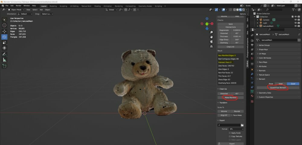
I set the new faces number to 4000 (50 times fewer faces than the original).

I Shade Smooth the surface.

I added two cylinders for a mat (that will support the left hand) and a base to write on it.

I added some text to add on the base following this tutorial.

Following the entire tutorial here is the result:

In the tutorial is not clear why, but you need to rotate the empty cube reference from 90 degrees otherwise it won't work.
I exported 2 STLs, one for the teddy bear and one for the base. I check the box Selection Only to be sure I only export the mesh I wanted.
Print the Teddy Bear in 2 colors in Cura
I watched this tutorial to see a convenient way to print in two colors with a one-nozzle printer. So first I installed the "Z-offset Plugin" from the Marketplace.

Then import the base, resize it, and take note of its height.

And print it.... 2 hours after it failed just at the last layer :'(

I try to restart a new one, but the 3D printer wasn't working properly, so I did a "reset factory", resend the E-Step value, and did the buildplate calibration. After 45min, the electricity stopped in the entire village (really! :-( ). I had to restart again...
Remove the base and import the teddy bear. I move it in Z with the height of the base (). On the params, I set a Z-Offset of 12mm.

And I remove any build plate adhesion type.

Then I send the second GCode to be started on top of the base.


Here is the result.


3D Print a complex form
To make use of the additive function of the 3D printer, I'll print a complex part that's hard to make with a subtractive method. I thought about a bearing. So first I need to design it, and I wanted to try OpenSCAD to do it.
Modeling in OpenSCAD
I follow this tutorial. But since it's not parametric, I will restart from scratch for a better understanding and make it 100% parametric.
So first I declared the first variables.
inner_bearing_radius = 4; //the inner radius where the bold will be
outer_bearing_radius = 16; //the outside radius of the bearing

bearing_thickness = 6; //depth-thickness of the bearing

tolerance = 0.2; //distance between the 2 rings and the balls
From those primary variables, I can calculate some dimensions for the 2 rings (inner and outer).
bearing_ring_thickness = (outer_bearing_radius-inner_bearing_radius)/2-bearing_thickness/4; //thickness of the 2 rings (inner and outer)

cutout_radius = bearing_thickness/2+tolerance; //radius of the circle that will "cut" the rings
To check if my values are correct I use the echo() function in OpenSCAD.

The two rings (inner and outer) are made like this:
// The 2 rings are made a rotate extrude from the 2 rectangles subtracted
rotate_extrude(){
    // the two rectangles are substracted with a circle of a radius same as the balls + a tolerance
    difference(){
        union(){
            //inner ring is first a rectangle
            translate([inner_bearing_radius+bearing_ring_thickness/2,0,0]) square([bearing_ring_thickness,bearing_thickness], center = true);
            // Same for the second one
            translate([outer_bearing_radius-bearing_ring_thickness/2,0,0]) square([bearing_ring_thickness,bearing_thickness], center = true);
        }
        translate([translate_radius_balls,0,0]) circle( cutout_radius ,$fn=50) ;
    }
}
Then I added the balls, I tried to put as many balls as possible. So I took the perimeters of the balls' circle, divided it by the diameter of each ball, and round down it.
translate_radius_balls = (outer_bearing_radius+inner_bearing_radius)/2;

balls_radius = bearing_thickness/2; //The balls have the same diameter as the bearing's thickness so it can be printed.

number_of_balls = floor((2*PI*translate_radius_balls)/(2*balls_radius)); // take the biggest number of balls that could go around the balls circle without touching the other balls.

angle_between_balls = 360/number_of_balls; // Devide 360 degrees by the number of balls
Then I just need a for() loop to create each ball.
// The balls are sphere moved to a certain angle
for ( ball = [0 : angle_between_balls : 360] ) {
    rotate([0,0,ball])
    translate([translate_radius_balls,0,0])
    sphere( r=balls_radius );
}
Then I can render it (F6) and export it in .stl. Here is the file.
3D print the bearing
As the Ultimaker is printing the Teddy Bear, I first print it with the Vertex (0,15mm profile and 10% infill).

The top was good, but not the bottom of it.

I needed to detach the balls from the rings.

I printed it also with the Ultimaker (0,06mm profile, 0,25mm nozzle, and 10% infill).

Here is the result.

It was perfect from the start. Of course, the spheres are not perfectly spheric but more than enough to roll.
In motion, the one printed with the Ultimaker is much better.
Files
Here are the files for the week.