Wildcard Week
Individual assignment
- Design and produce something with a digital fabrication process (incorporating computer-aided design and manufacturing) not covered in another assignment, documenting the requirements that your assignment meets, and including everything necessary to reproduce it. Possibilities include but are not limited to wildcard week examples.
Plasma cut a Traffic Sign

For my Final project, I need 2 aluminum plates cut with a special shape. The front and the middle layer of the Traffic Sign).
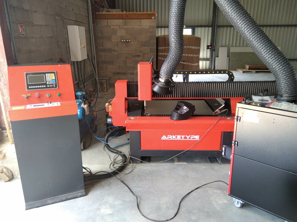
At our lab, we have a Numerical Plasma cutter. (In the picture, the machine before we move to our new place). The machine should be replugged this Monday. So I'll take the chance to cut something from my final project

source Hypertherm
The plasma torch is Dual flow plasma shielded, which means the nozzle is insulated from molten metal allowing drag cuttings.1
Safety
As a plasma cutter machine, there are 5 main issues regarding safety. They are documented for the Safety manual of Hypertherm.

source Hypertherm
Arc rays can burn eyes and skin
So we need to cover our skin and wear a helmet to be protected from it.

source Hypertherm
A plasma arc can cause injury
A plasma can easily cut through gloves and skin, so keep away from the torch, do not hold metal near the cutting path.

source Hypertherm
Toxic fumes can cause injury or death
The plasma torch does not produce toxic fumes, but the melted metal does. Especially the stainless steel that does have a chromium layer. The fume of it contains Chromium (IV) which can be very toxic (cancer, respiratory issues, etc.). So for that we have this fume extractor. We can also try as much as possible to remove all coating and solvents from the metal before cutting. Use good ventilation.

source Hypertherm
Cutting can cause fire or explosion
A torch a can be super hot and cause a fire. So we need to make sure the cutting area is safe before doing any cutting by removing all flammables within 10 meters of the cutting area

source Hypertherm
Machine motion can cause injury
Of course, it's still a CNC machine, so when operating it we need to be careful with the materials, the movements of the machine and the noise.
G-code for plasma
source Hypertherm
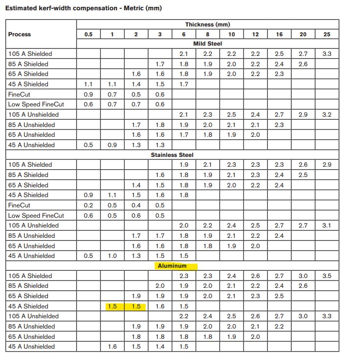
Something I need to have in mind is the kerf of the plasma. It can change depending on the material and the Amps of the plasma cutter. Hopefully, the constructor made a good cutting chart.

So I decided to give a first try to the simple square in square shape. At the lab, we use FastCAM as the plasma CAM software. In the Path settings, as explained here I can set the Kerf radius (the previous image show the diameter!).
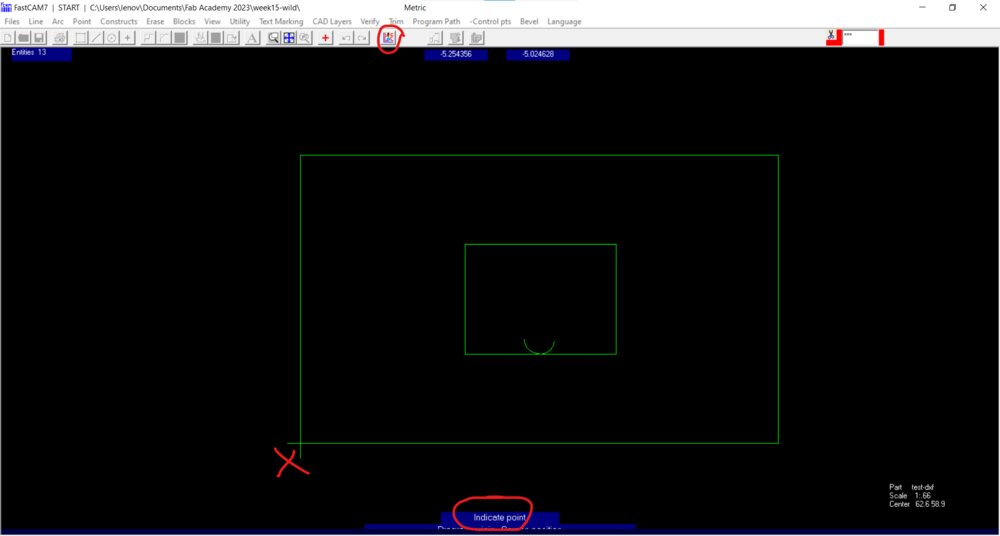
Then I can generate the G-Code already. When clicking on Output NC code. It asks for the speed for entry and exit, to set the starting point and the endpoint (I set it up to return to the entry point). We can already see the entry point. The plasma is starting outside of the path to not let a mark. And it is smart enough to know the inside and outside of the piece.
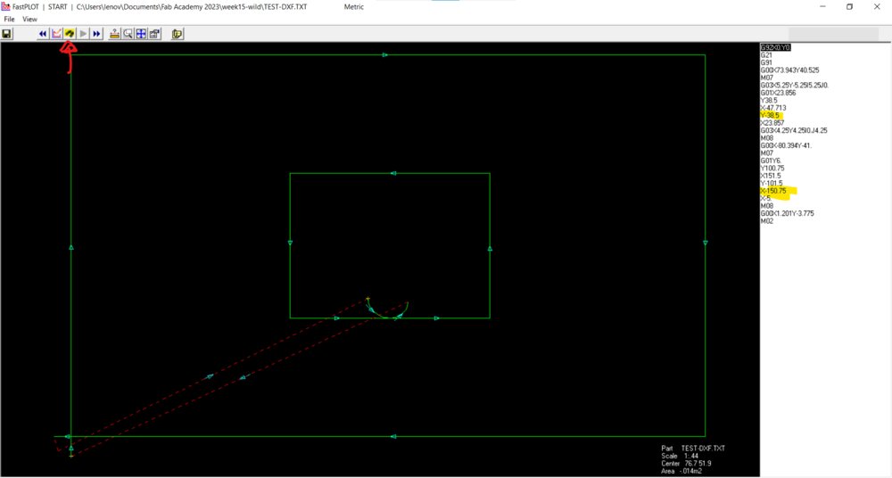
Then I can check the toolpath. We can see that the kerf has been noticed. And we can see that it will start with the small square and then the outside cut.
On the machine
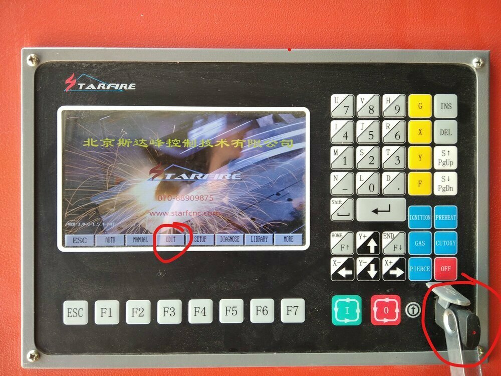
Once the machine is turned on, the USB disk with the GCode on it plugs in. I can go to the EDIT menu (F3).
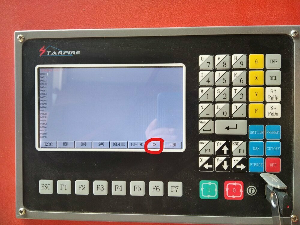
There you can then go on the USB (F6).
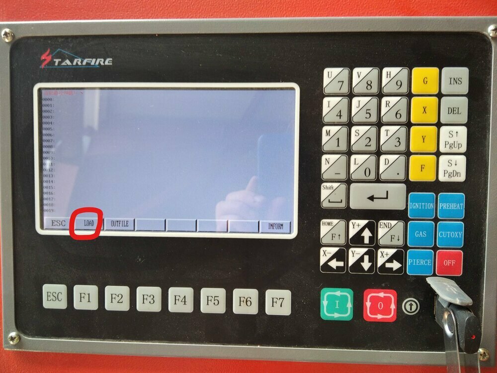
And then LOAD (F1). There I was able to search the USB's folder and find your G-Code.
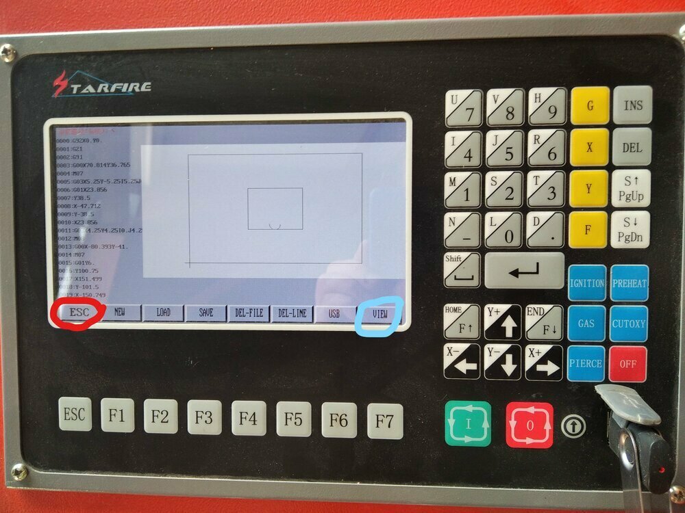
When you have found it, you can click on VIEW (F7) to have a look at the toolpath. If it's good you can go back to the main menu by clicking ESC.
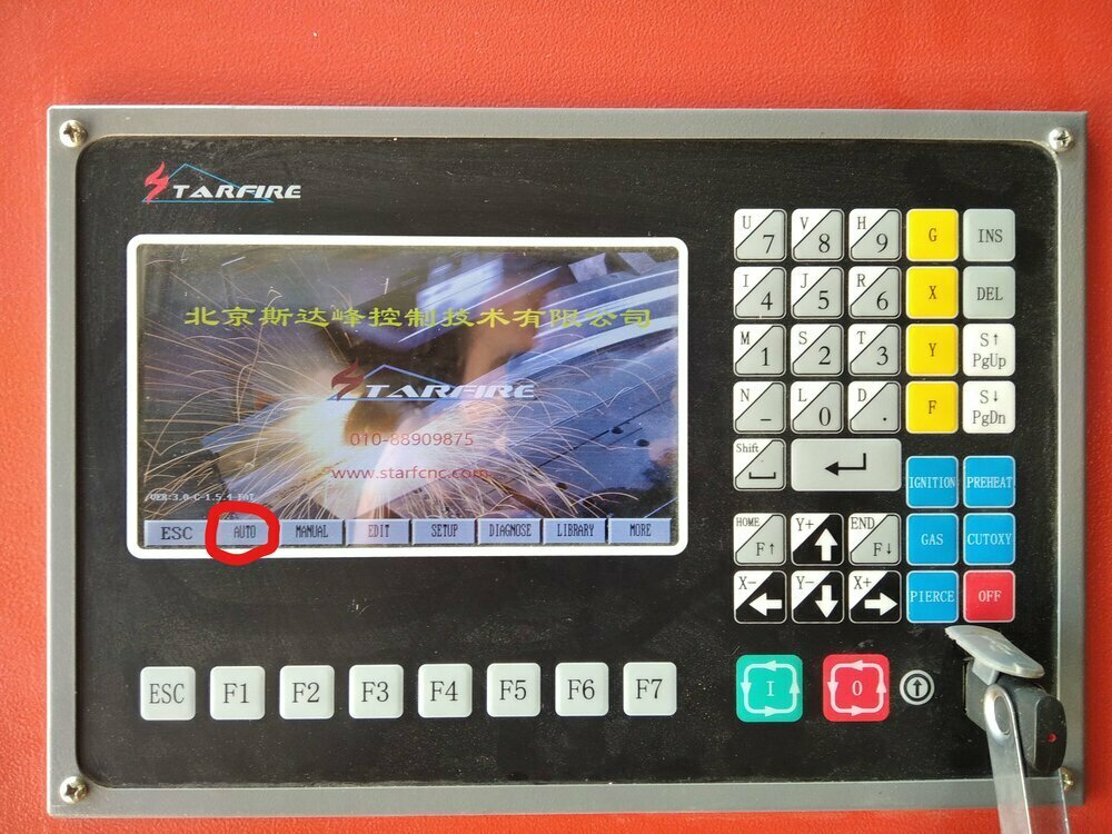
Now we can go to AUTO (F1).

There, you can click on VIEW (F4) to have a look a the cut order (N-PIECE, F1) and the Startup point (STARTP, F2).
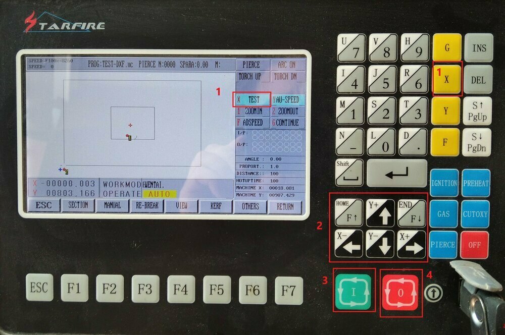
And the AUTO menu I can then run a test in the air by activating the TEST mode (1). But before that, I had to move the head where I wanted to start with the arrows (2). Then I clicked on START (3) and if needed I could stop with (4).
Here is a video of a test in the air.
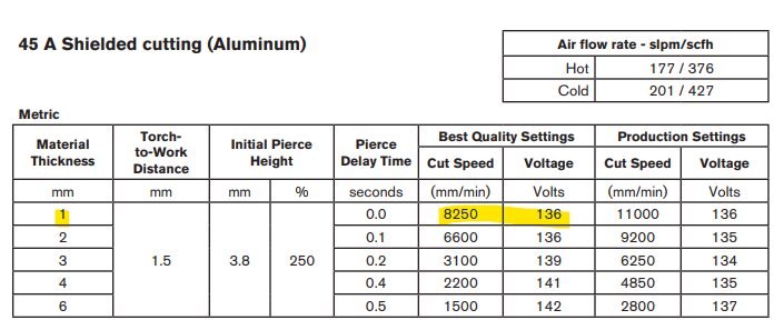
On the machine controller, I need to set the voltage and feedrate of the machine regarding my material and the Amps chosen.

Those parameters can be then set on the bottom panel of the machine controller.
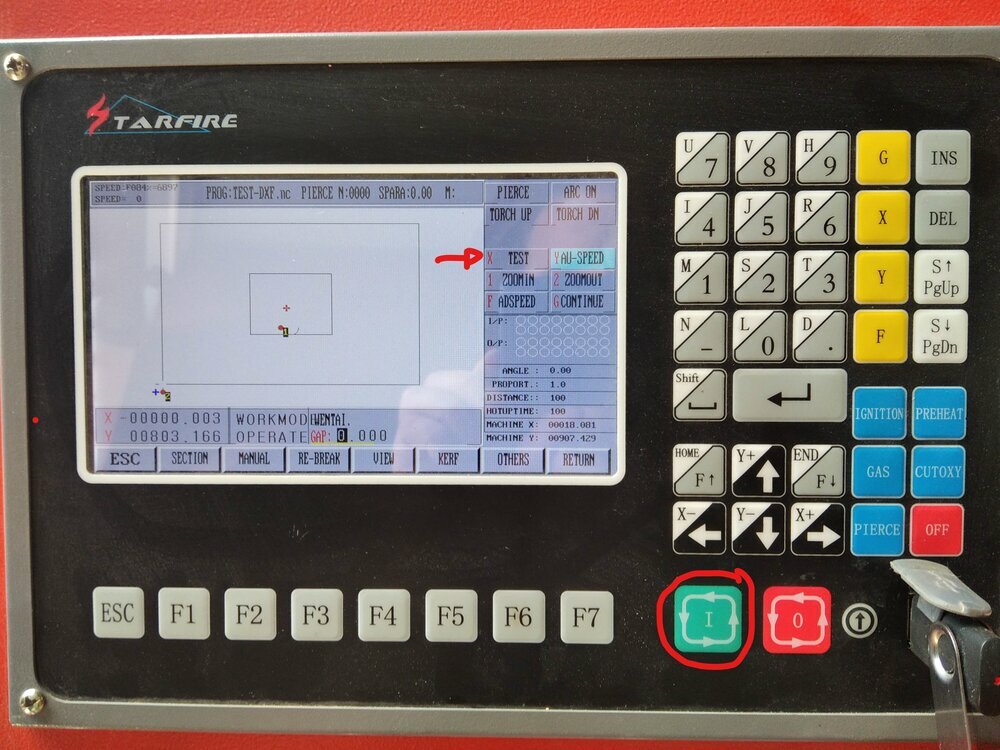
When set, the last thing to do is to launch the path by deactivating the test mode and pushing on start. For each cut of the toolpath, I had to manually restart after a small arc strike. Too quick and the arc has not been initiated, too slow and the arc has made a hole.
Here is the video of the cut.
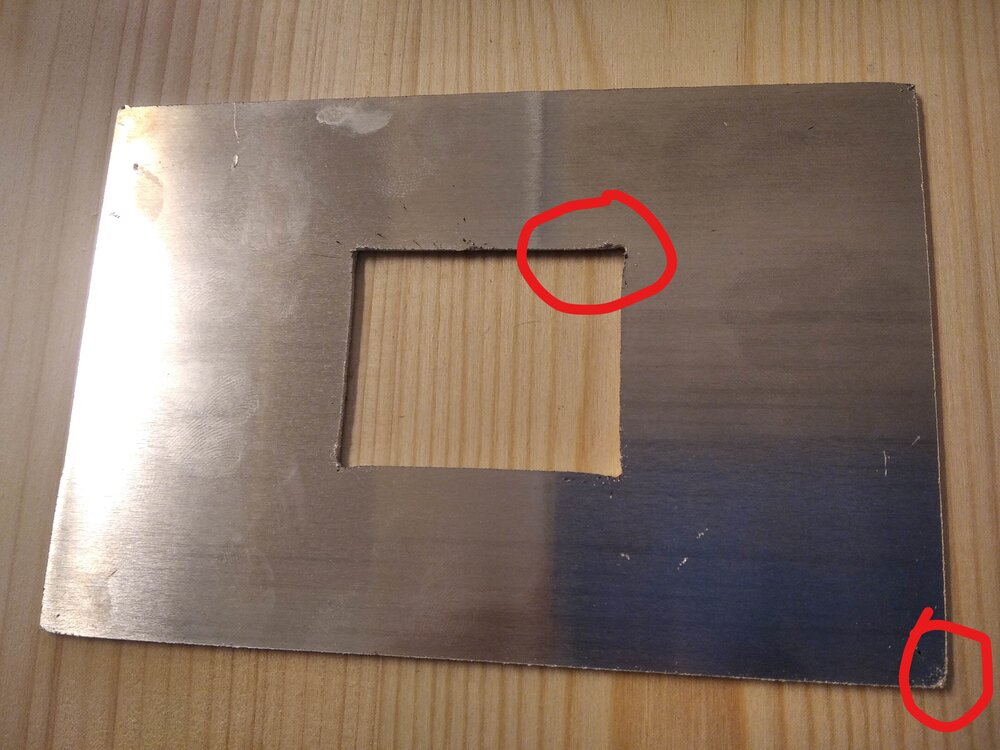
The aluminum plate was really thin. So when the torch cut the corners, the speed drops down and it melts more. So the corners are not really clean. the solution will be to create some small fillets at the corner so the torch can keep its speed.
More Plasma cuts can be found in the final project.
PCB with a Vinyl Plotter
I designed a Step Response Module for the Input Devices week. As I wasn't able to try to create a PCB from a copper sheet cut with a Cutting Plotter I wanted to take a moment this week to try it.
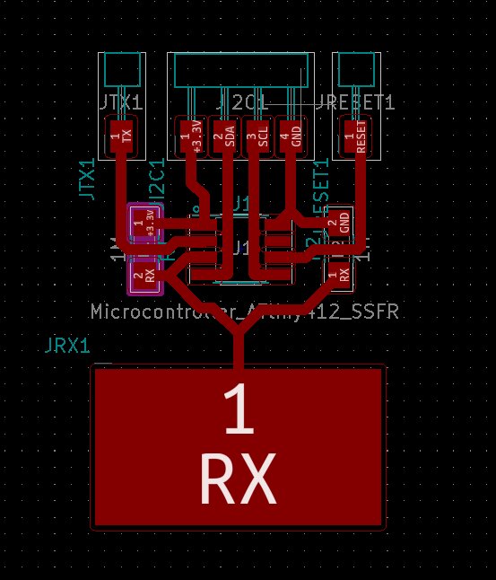
I try to design pretty thick tracks, but as the ATtiny412 has such a small footprint, we will see. See week 11 for more details.
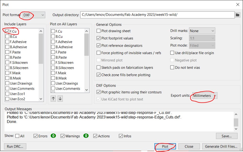
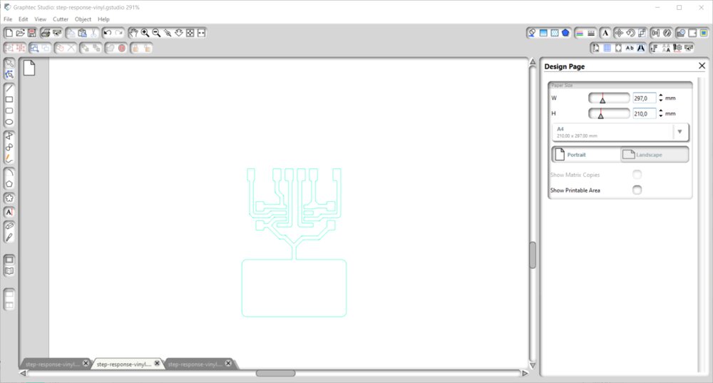
As the Graphec Studio that pilots our plotter needs DXF files, I export with that in mind. (Files > Plot). Be careful to choose the right unit. All my components are surface mounted (SMD), so I just need the front copper layer (F.Cu).
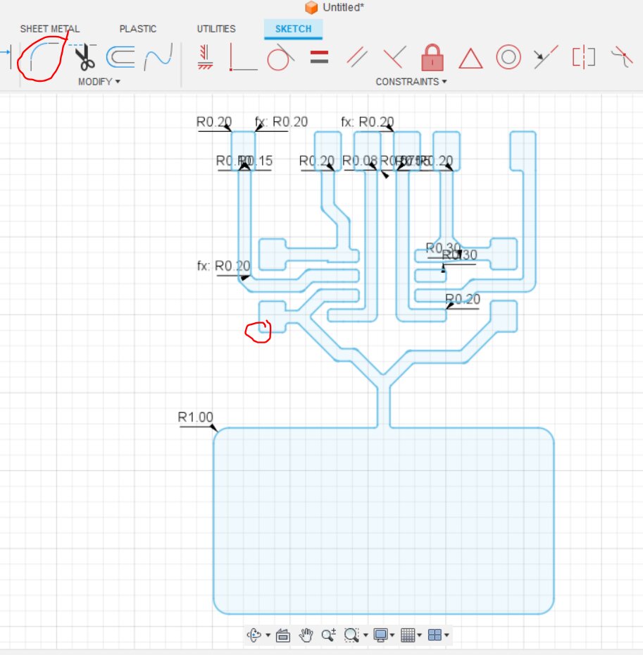
The plotter doesn't like sharp corners, so I edited the DXF file on Fusion 360 to add some radius corners.
So time for some tests. The last one seems ok. It's a slow speed, , the slowest possible on the machine. And the force is 14. But the corners do not like super right.

Weirdly, when importing the modified DXF in Graphtec Studio, the paths looked terrible.
So the trick I used was to export ESP in with Inkscape as it's also a format that can be used in Graphtec Studio.
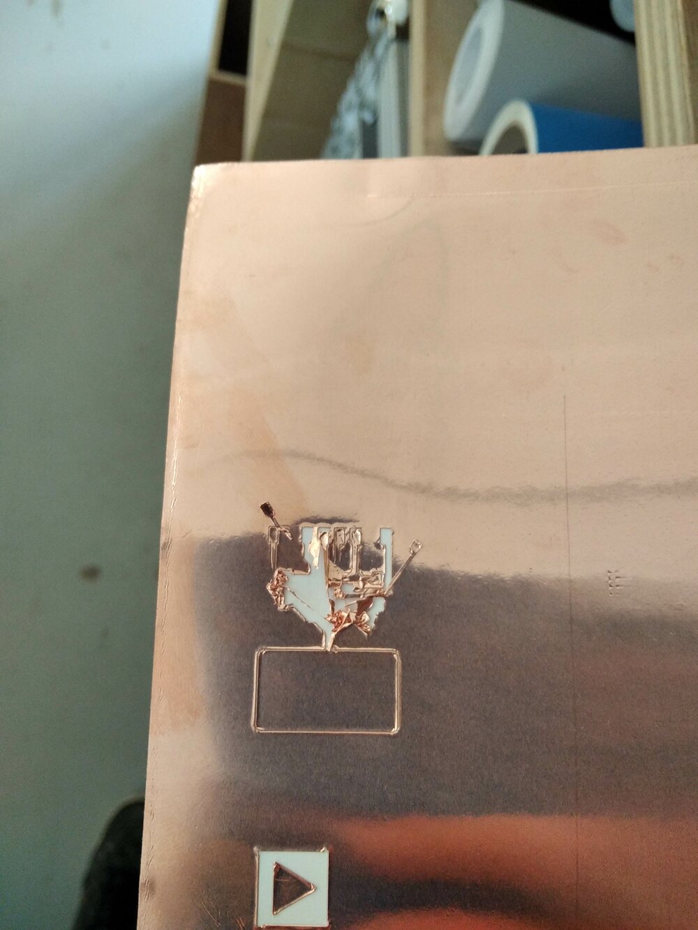
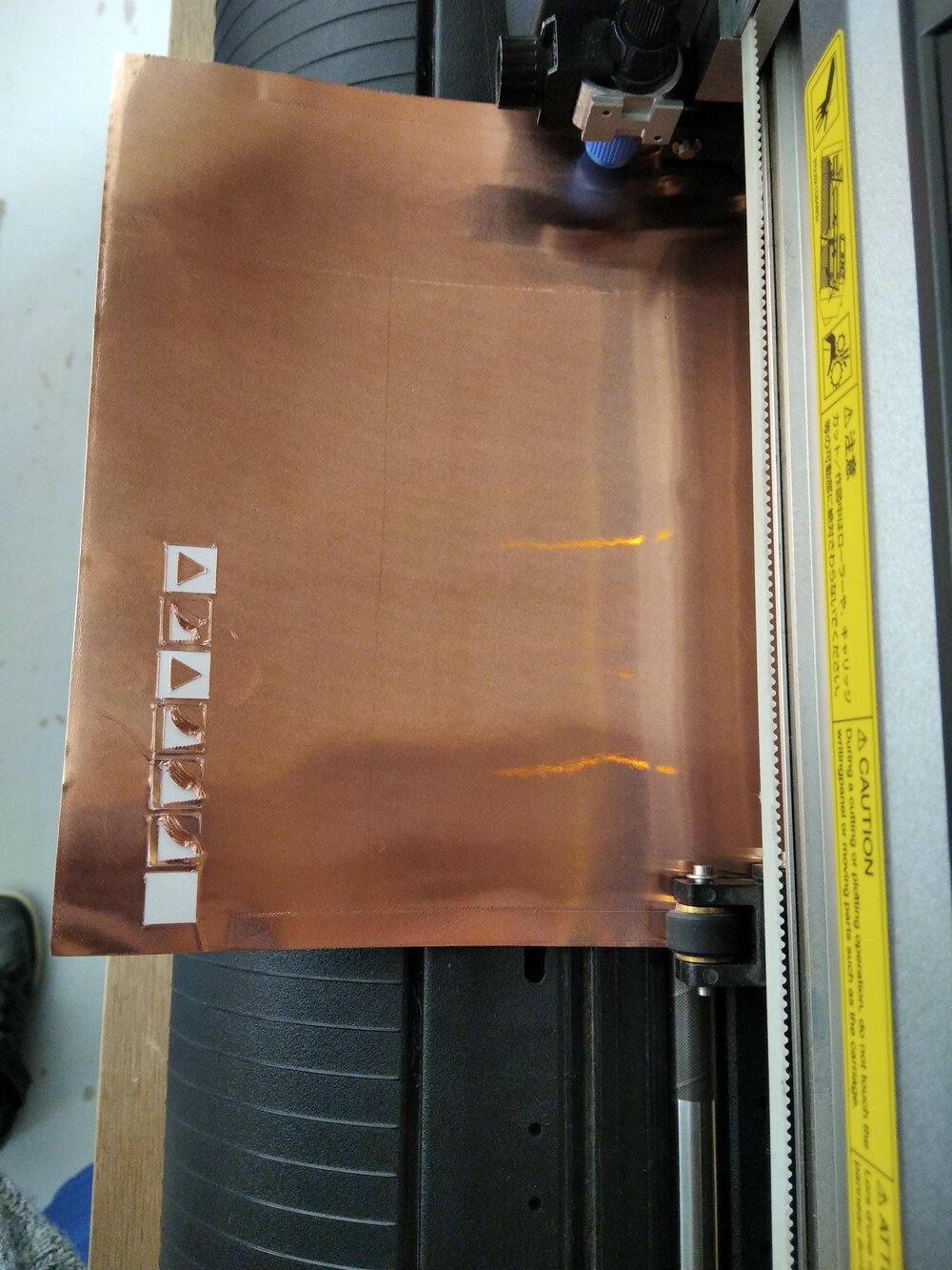
So let's try a first test! And ... it failed ...
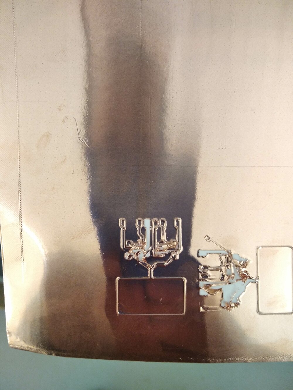
So I try by changing the offset of the blade. But still, the tracks are too narrow.
Based on an advice from Marius during the Open Global Time, I decided to simplify the tracks (Thanks!). So I'll make them as thick as possible and as straight as possible.
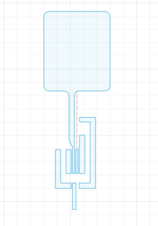
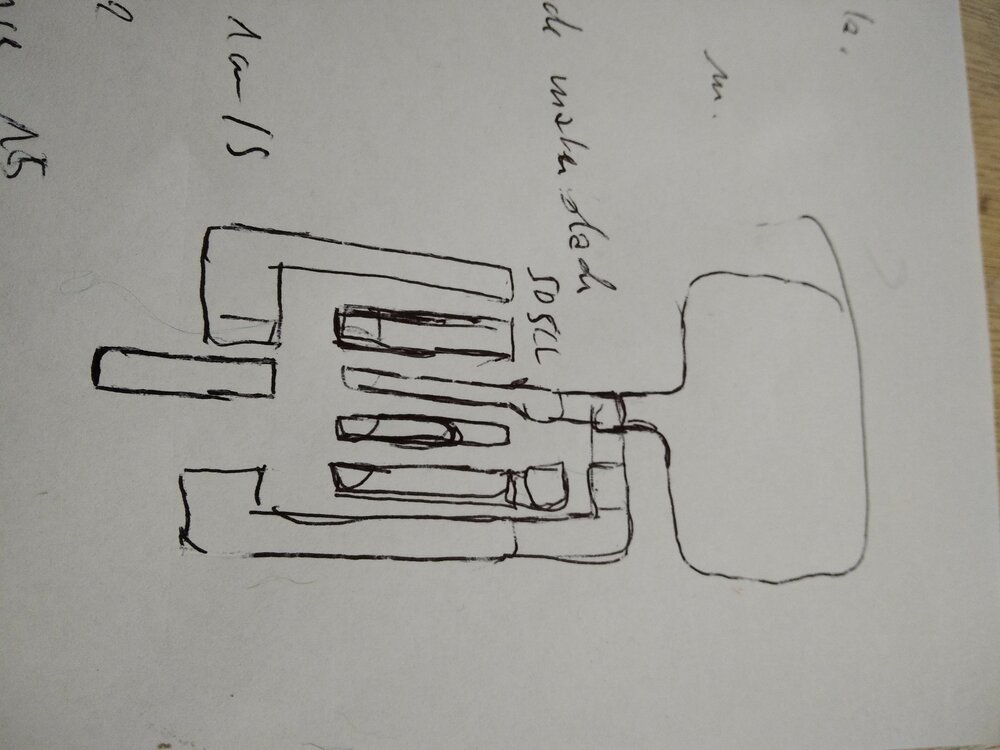
As the circuit is pretty simple, I designed it directly in Fusion 360. The only thin tracks are the TX and RX pins, I had no choice as there are in the middle of the MCU, but there are straight. As I don't use the PA3 pin I even could make the track of the UPDI pin a bit thicker.

I decided to put a new blade on the potter. After one first fail, I used a softer force of 5 and it went well.

I had some difficulty peeling off the copper, as the small tracks were coming with the exterior. But I manage to restick them.

I then use a transfer paper. I was afraid of this operation as I read that is one of the most difficult parts of the job. But actually, it was straightforward.
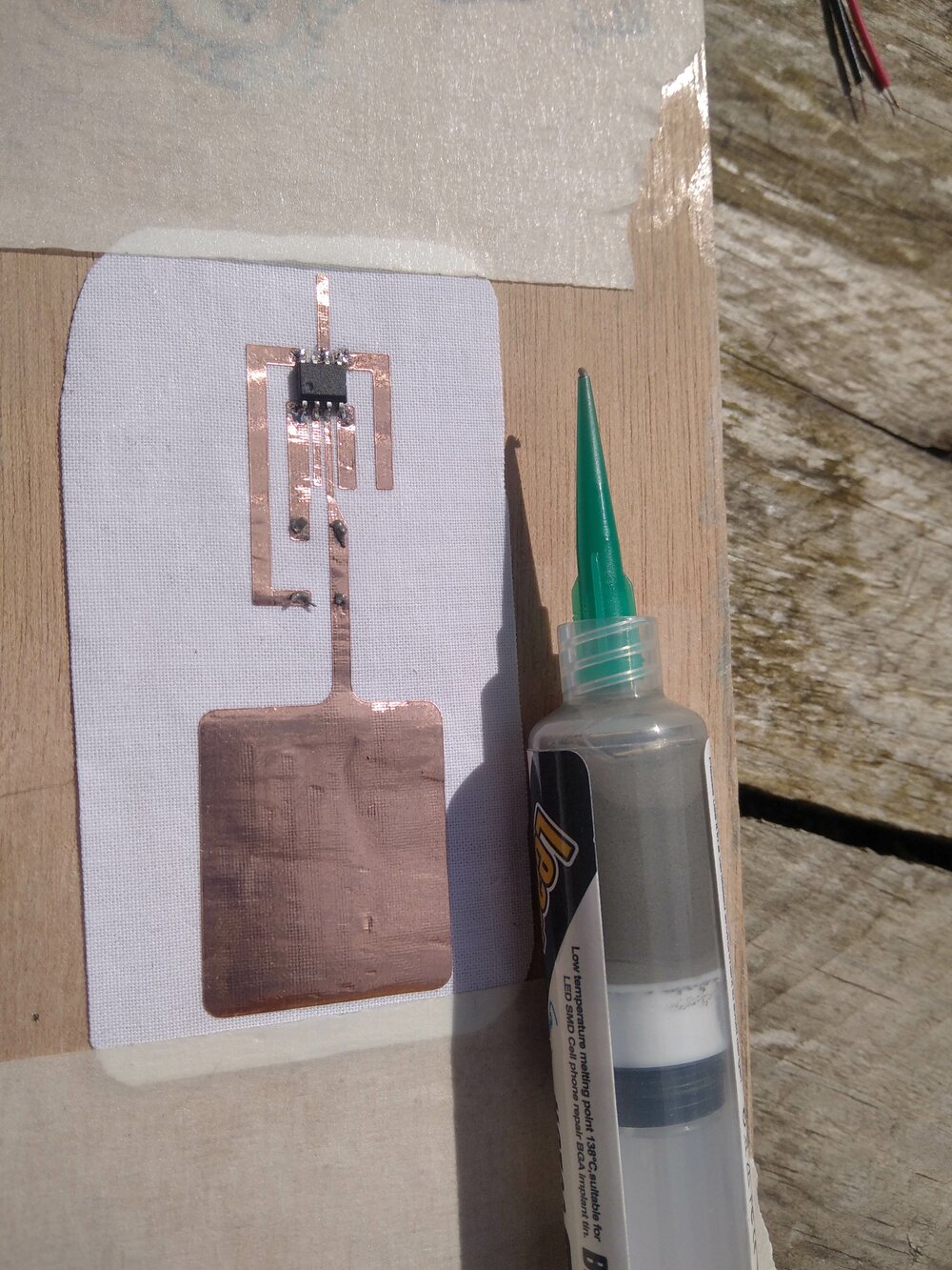
I bought also some low-temperature solder paste (138°C). I use a small soldering iron set to 300°C so it can melt the paste quickly.

I was really quick and clean. I added some wires to connect UDPI, TX, I2C and the power.
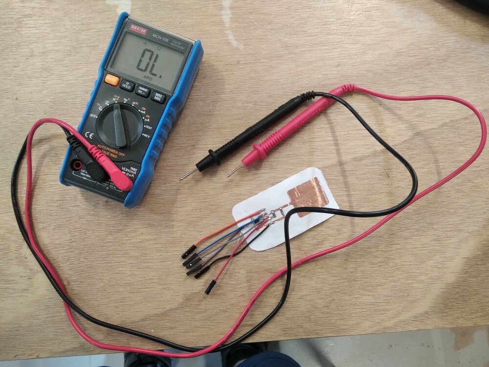
I checked if all the connections were good, and they were!
Program the ATtiny412 Board
source @amidarius
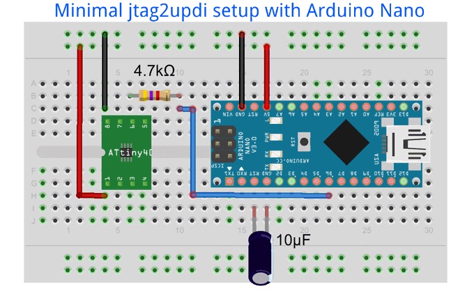
As I don't have a proper programmer, I watched this video to flash the ATtiny412 with an Ardunio Nano. So first I uploaded jtag2updi.ino into the Arduino Nano board. Then wired my board like in this setup.
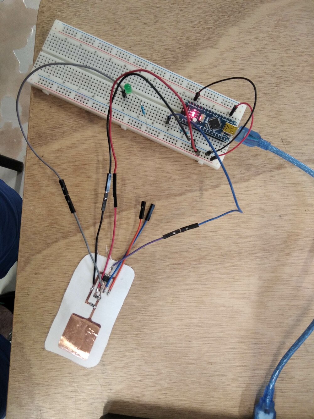
So here we can see the capacitor for the bloc the rest of the Arduino Nano. And the resistor between the UDPI pin of the ATtiny412 and the Arduino's D6 pin.
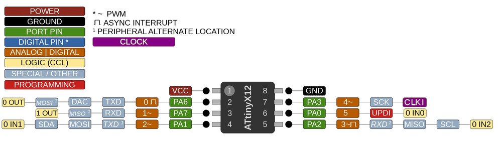
source megaTinyCore
The idea is to do a first "blink" LED from the ATTiny412.
I help my self with pinout diagram and choose to connect the LED to the PA6 as it available for the TX step response.
Once jtag2updi and the megaTinyCore are installed on the Arduino IDE, I should be able to push some code to the ATTiny. But no... I add this error:
avrdude: jtagmkII_getsync(): sign-on command: status -1
I spend 3 hours trying to find the origin of the errors, but I have no idea were it really come from. I know it means the my board is not propelly detected. But even with the alexandra's assignment where she faced a similare issue, I could found the solution.
So I decided to refollow another tutorial from Adam Harris' article from the Blog **SheekGeek.
And there I successfully upload an empty sketch! For me, the solution came from here : ArduinoISP as the programer and the SpenceKonde version of jtag2updi](https://github.com/SpenceKonde/jtag2updi).
So now I'll check if the ATtiny 412 can do anything, so let's try to push a simple LED blink code.
#define LED 0

void setup() {
   pinMode(LED,OUTPUT);
   }

void loop() {
   digitalWrite(LED,HIGH);
   delay(100);
   digitalWrite(LED,LOW);
   delay(100);
   }
And it's working! I flash my first MicroController without a bootloader. 😃
Next job is to mount the step response with the conductive fabric and create the code to send the step response throught I2C to another microcontroller. To be continued...
Files
Here are the files of the week:
Plasma
Vinyl PCB