Computer-Controlled Cutting
- Linked to the group assignment page.
- Explained how you created your parametric design.
- Documented how you made your press-fit kit.
- Documented how you made something with the vinyl cutter.
- Included your original design files.
- Included hero shots of your results.
Spiral Goals
- Check the focus, power, speed, kerf, and joint clearance of the Arketype CO2 laser (Assignment)
- Redraw the week mockup to design a laser cut scale model of the Final Project, including 2 different joints (Assignment)
- Make the logo cut with the plotter and put it on the scale model (Assignment)
- Cut the scale model with the laser and assemble it (Assignment)
Laser CO2 parameters
As I'm doing the Fab Academy remotely, I had to do the group assignment myself on the machine of my lab.
Update 12/03/2023
At the lab we have ArkeType), here are the specifications:
| Items | Value |
|---|---|
| Working Area | 90 cm x 60cm |
| Power Laser | 100 Watts |
| Engraving speed | 0-50000 mm/min |
| Cutting speed | 8 000 mm/min |
| Raster engraving | Maximum 2500 DPI |
| Precision | <0,01 mm |
| Taille mini des caractères | Lettre 1,0 x 1,0 mm |
| Files formats | BMP, PLT, DST, DXF, AI, CDR |
| Alimentation | 220V ± 10%/50 Hz, 110V ± 10%/60 Hz |
| Size | 1400 x 1030 x 1050 mm |
Security
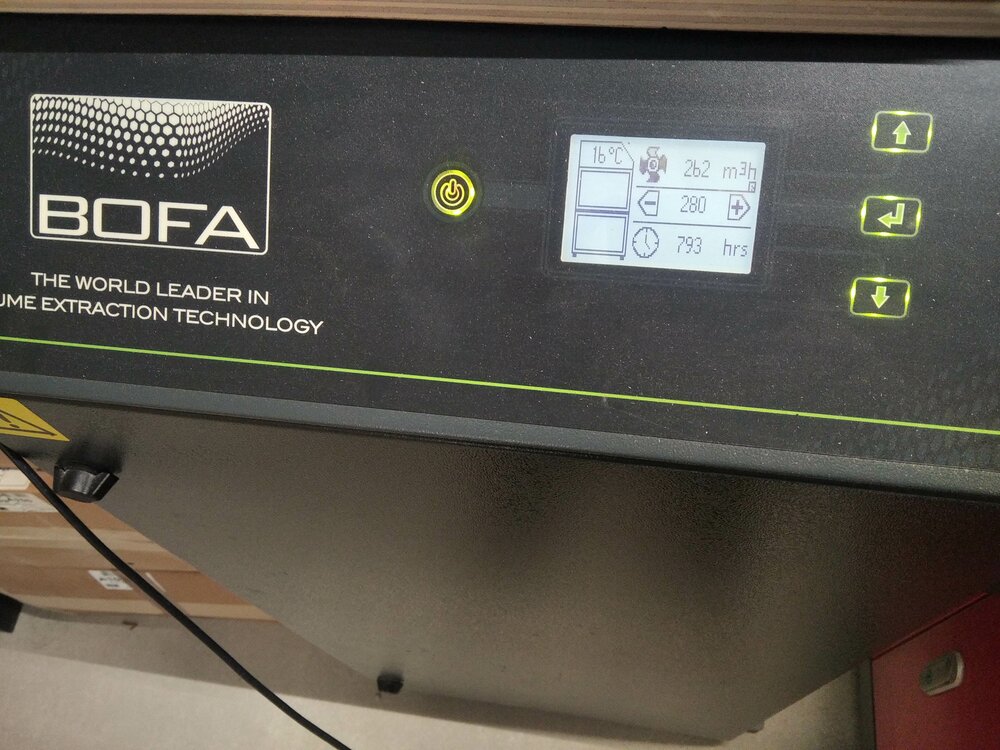
For the fumes of the laser, we have an BOFA AD, that we turn on when the laser runs.
Of course, there is also a stop button in case of emergency.
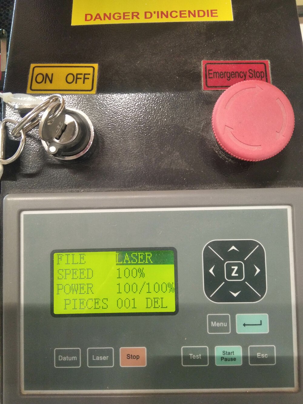
Starting up
When we need to launch a job on the laser, we need to first turn on the laser (It automatically turns on the water cooling, but not the fume extractor). We can move the laser nozzle with the arrow from the X and TY axies. Usually we use the top-right corner of the drawing as the origin. That how I know where to put the nozzle on the material.

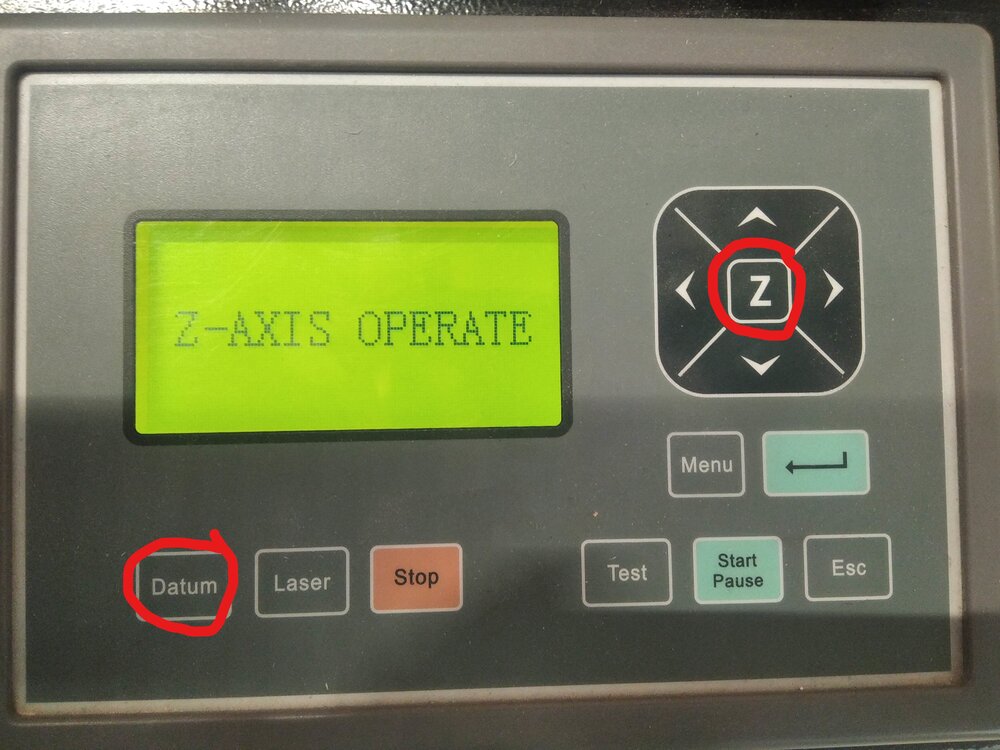
To set the auto-focus, we need to operate in the Z axe, by click on the Z on the dashboard. Now, I can move with the up and down arrows to move the working area. While my nozzle is on top of the material I want to cut, I can than click on Datum to set the focus, helped with the sensor button next to the nozzle.
When it's set, on the computer connected with USB to the laser, in the Lasercut 5.3 software we can import or draw vectoriel design to cut or engrave. Once the settings are good, we just need to click on the Download button to send the laser operations to the machine.

Once is downloaded, we can click on
Focus
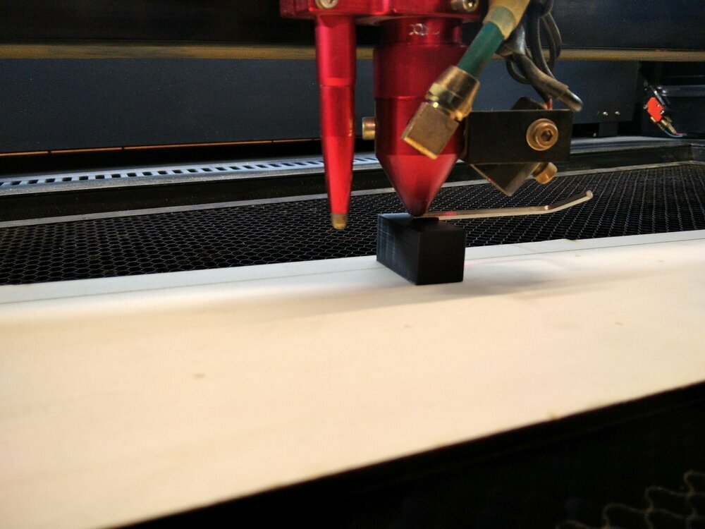
For the focus of the laser in my lab (ArkeType), I used a "ramp" method. I put a piece of wood like a ramp starting at the real bottom of the laser nozzle.
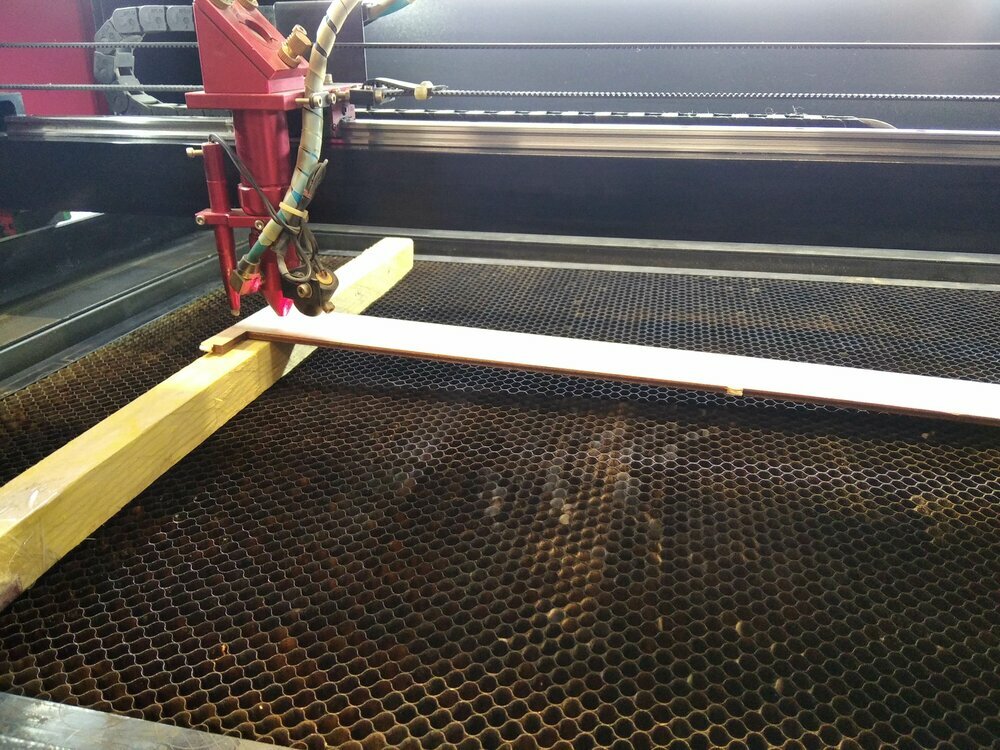
Then I can burn a line from the top to the bottom of the ramp.
After identifying the finest line, I measured the distance with the nozzle.
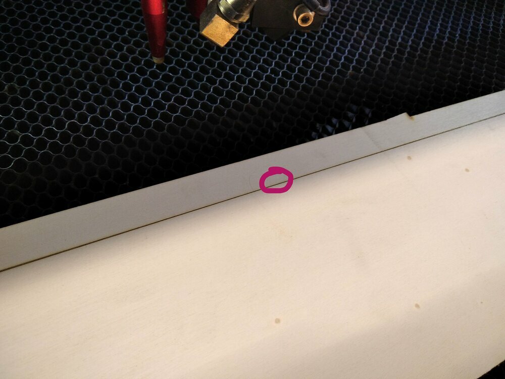
It appears to be perfect regarding the auto-focus already configured.
Power and speed
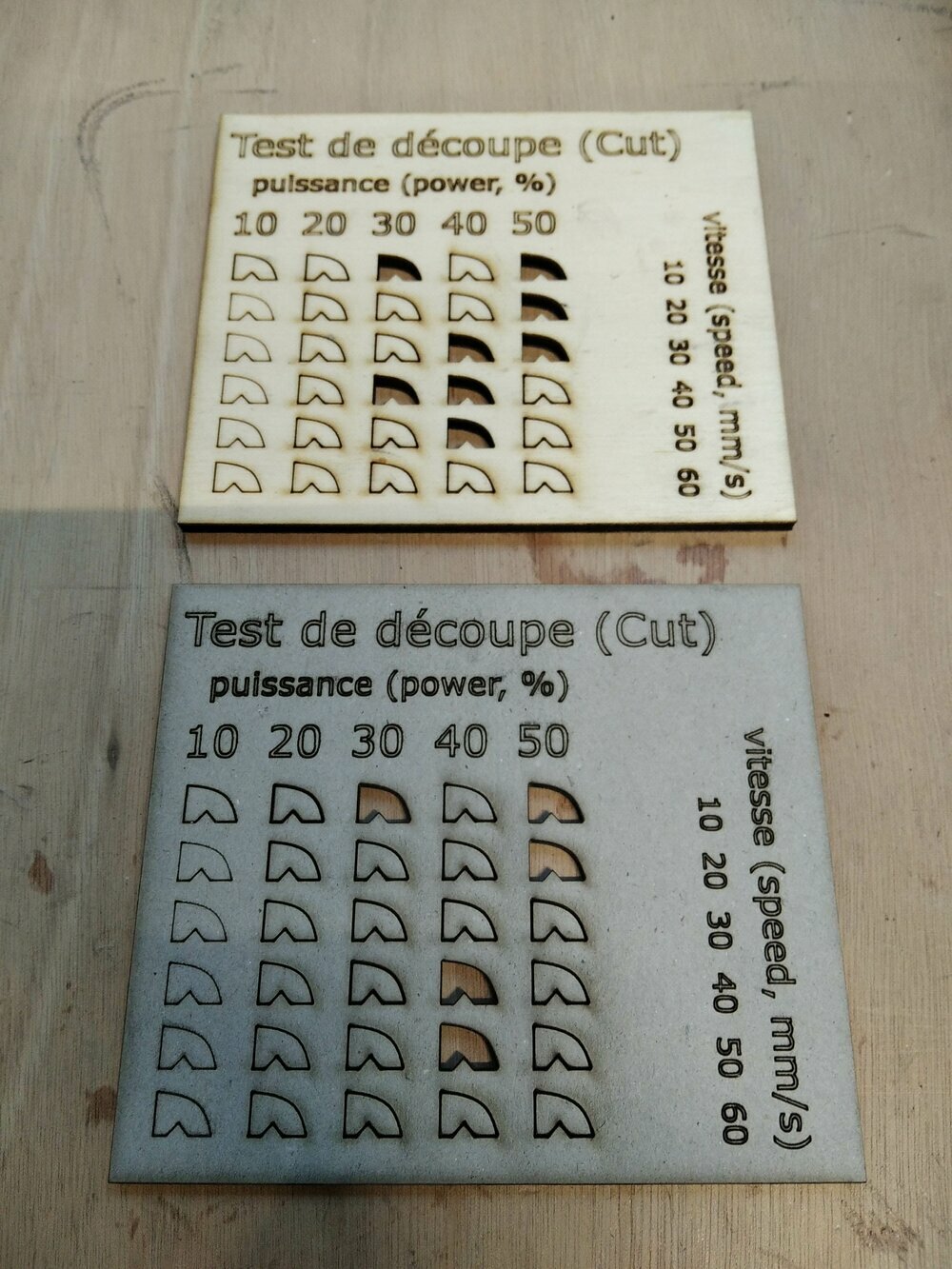
Next, I wanted to do a nice matrix of power/speed tests on 2 materials. As we don't run Lightburn as our laser software, but the one from the machine constructor, I need to redraw a test matrix from the start. the number of layers is limited, so I run it from 10 to 50% in power and 10 to 60 mm/s in speed. (I did it in French and English so the members of the Fablab can use it too).

Weirdly, the difference between the marked and the cut parts should have been diagonal, but instead, some parts stayed fixed. For the plywood it can be understood as some parts of the material can be stronger or softer, but for the cardboard is more bizarre.
Kerf
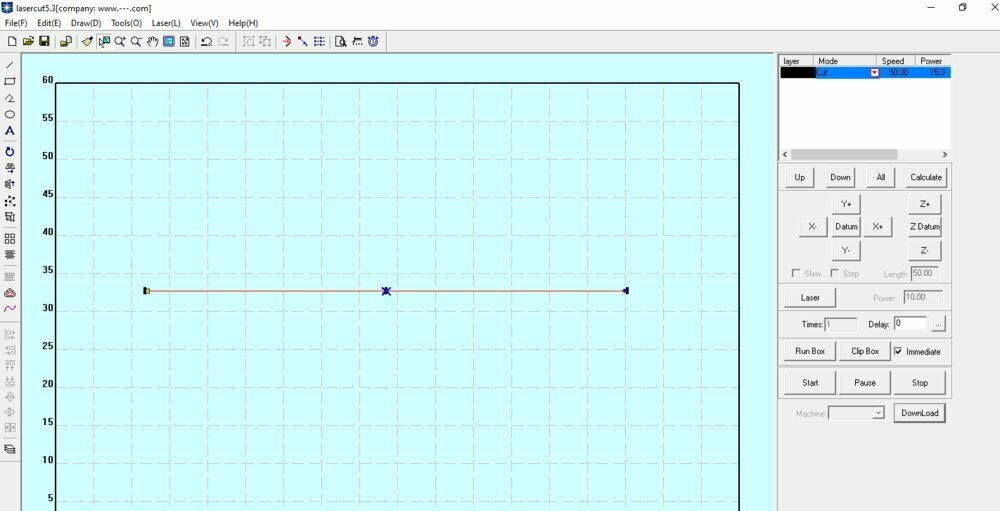
For the kerf, I just draw some squares directly on the LaserCut software. Their width is equal to 20mm. Here is the SVG file. I set the power to and the speed to (not like the screenshot).
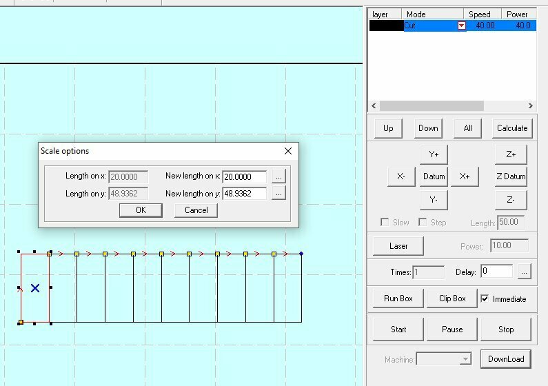
Taking 7 pieces, I measured them, and instead of as expected, I had .
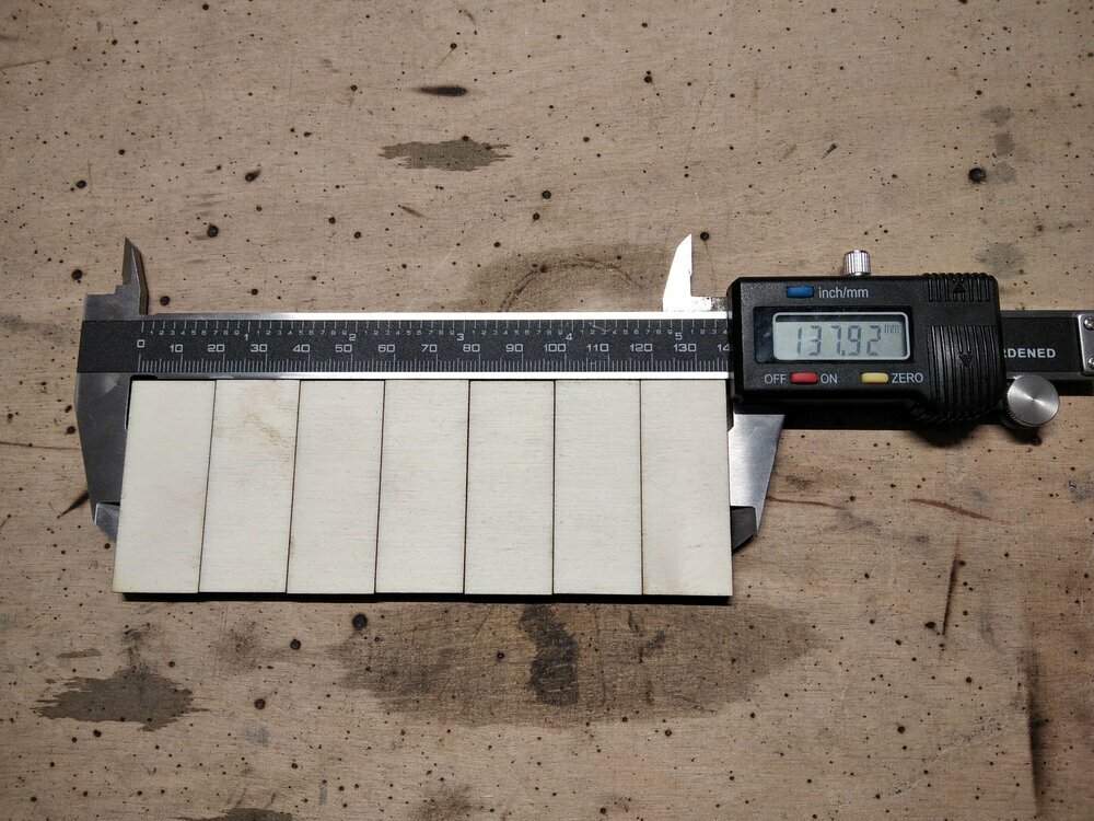
If you subtract it with the designed length en divide by the number of lines you have the kerf(~diameter) of the laser
Joint clearance
Now that we have our kerf, we can try different offsets to fill the gap of the kerf. To fit the kerf, the path needs to be at the kerf divide by two
I draw a single finger joint and a circle fitting in a hole, inspired by this, but since Lightburn isn't compatible with our laser, I needed to redraw as I did for the cutting test.

I did 4 offsets from the kerf with steps of .
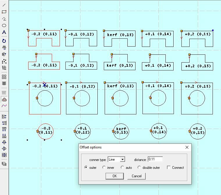
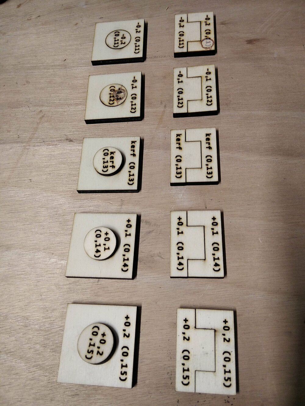
All the finger joints were fitting perfectly, was the better actually. But for the circle in the hole from , it's starting to not fit anymore.
Snap-fit joints
As I want to use some snap-fit joints for my scale model, I need to find the best parameters for it. So I created a new FreeCAD file for it. Compliant Joints are real science, that takes time to master. Here I'll just make some tests to find some joints that are working.

source: SMlease Design
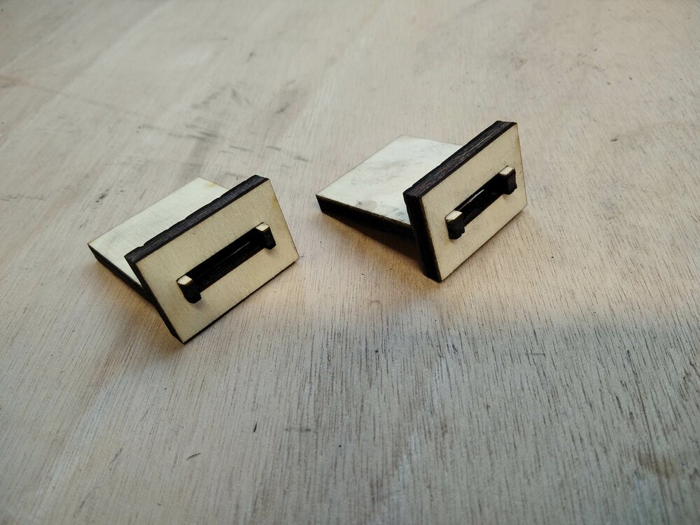
I draw 2 snap-fit joints with some arbitral measures taken to some literature. Some important measures are the deflection length (meaning the nose's length of the snap) and the thickness of the snap (the finer, the easier it will move, but the wackier it will be). I started will a thickness/deflexion of 3mm/1mm and 2mm/1,5mm.

I exported the sketch (select the sketches then Files > export).

Then import the DXF files into the LaserCut software. I did an offset of as seen in the Joint clearance section. Then cut some first pieces.
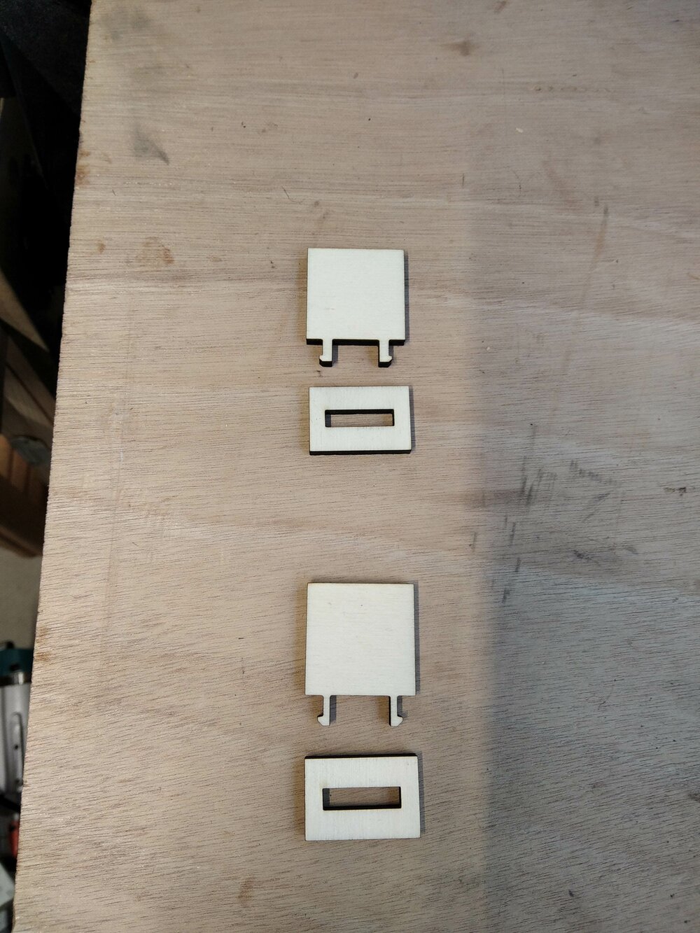
It didn't go well. The 3mm/1mm broke the end-piece joint and on the 2mm/1,5mm one of the snap broke.

So I did another try by changing the snap_deflection variable to and the snap_entrance_angle to . It worked wonderfully, but the joints were moving.
So I reduce the height of the snap from to , and that's a perfect fit! The snap-fit joint with a thickness of 3mm is a bit harder to put in but looks stronger, so that's the one I'll choose for the scale model.
Back to FreeCAD - 3D parametric modeling
Some insides
After last week's failure, I had a video call with one of the FreeCAD forum's members (nice community there!) He told me that I should use some geometrical sketches and use a "sub-object shape binder" to create the pad body. Another thing that he told me, is I don't need to create a Datum plane. If there is a normal line in a sketch and a point (vertex) I want my new plan sketch to pass by, I just need to select those and "create a new sketch".
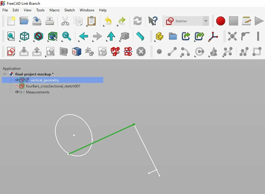
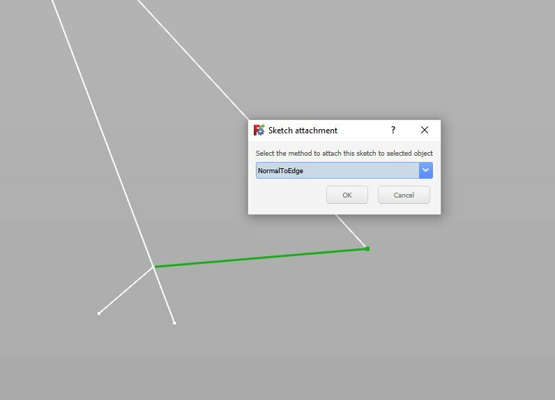
Then FreeCAD will automatically propose some propositions for the orientation/attachment of the new sketch. In my case I selected "NormalToEdge".
New parameters for the Scale Model
For the 5mm plywood scale model, I create new variables that I'll use for the design.
| Scale Model | ||||
|---|---|---|---|---|
| plywood_thickness | 5 | mm | ||
| bolt_diameter | 5 | mm | ||
| fourBars_thickness | 15 | mm | ||
| frameLarge_thickness | =100 * $B$1 | mm | ||
| snap_thickness | 3 | mm | ||
| snap_deflection | 0.5 | mm | ||
| snap_exit_angle | 100 | deg | ||
| snap_entrance_angle | 25 | deg | ||
| snap_root_radius | 1 | mm | ||
| frameSmooth_radius | =100 * $B$1 | mm | ||
| tolerance | 0.1 | mm |
Drawing the shapes and first bodies
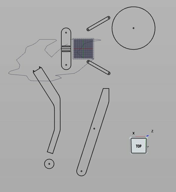
After that, I started to draw the sketches that I will use to create the bodies of the scale model. Starting by the rear of the trike.

As I wanted to use LCInterlocking module that will let me generate finger joints automatically, I draw my shape to both pads that will touch each other but not intersect.
Then I started to extrude some "pad" from the sketches. Setting the length to the parametric value plywood_thickness (in my case 5mm).

When the 3 rear pads have been done, I wanted to try the mirror function to create the left part of the tricycle. I select the pad in the body to mirror it.
Back to the vertical sketch and let draw the main frame. But I first created the front wheel pad. And then select the face where the frame will be fixed to.
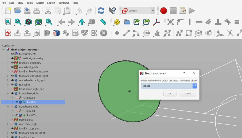
And when the sketch is done, the same for the back of the main frame.

Let's make some joints
The first joints I wanted to try are the Snap-fit joint to link the main frame to the rear four bars linkage.

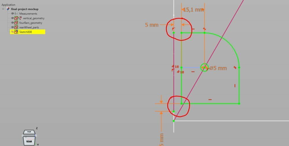
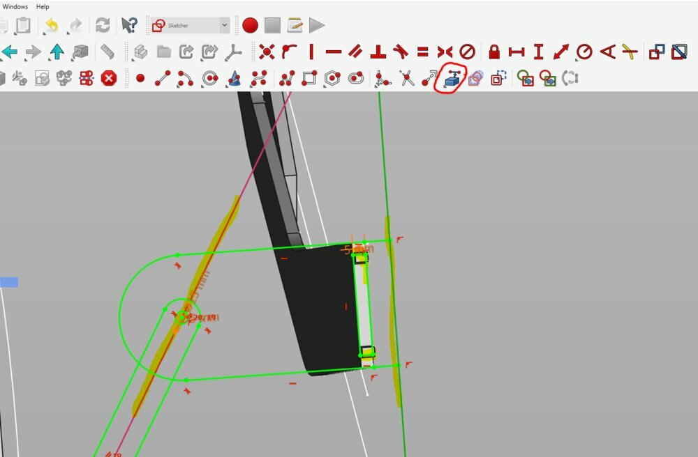
Now I can start the last sketch I'll need for this scale model. So I selected the face between the snap-fit joint.
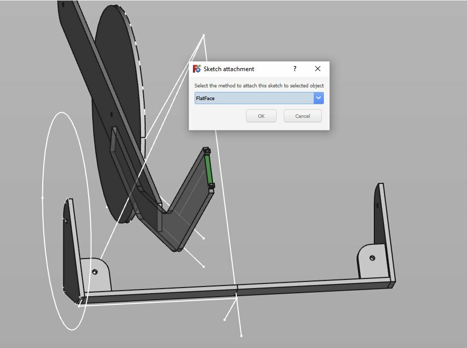
Like I did with the previous sketches, I had to import some lines with the Add external geometry function.
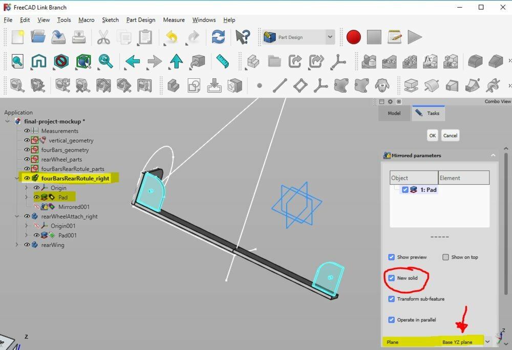
From that sketch, and still using the sub-object shape binder, I created the right side of the four bars linkage. I also created the pad from the previous sketch rearWheel_part so I have the entire right side of the trike.
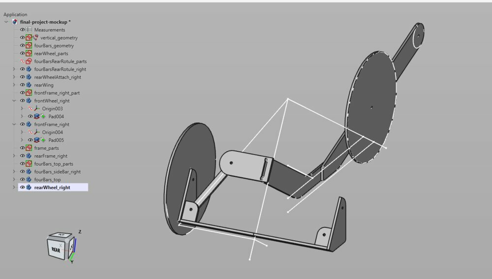
Again, let's use the mirror function to create the left side. Like before, I select the body and the pad I want to mirror, go to the `mirrored function, and chose the Base XY plane* as the symmetrical plane.

And here we go, the 3D scale model is ready.

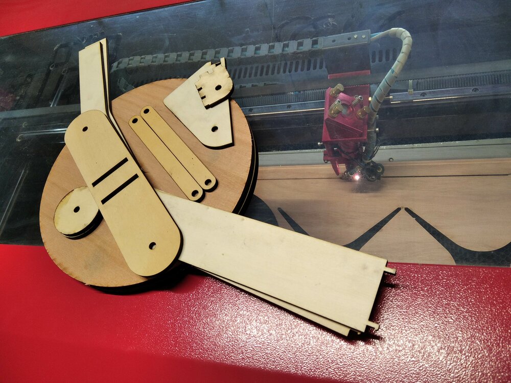
Laser cut the scale model
As I said, there is a laser module that you can add to FreeCAD. I went to Tools > Addon Manager and looked for LCInterlocking. I learned how to use the LCInterlocking Workbench with this youtube tutorial.

So first, I created a copy of all the bodies (so I don't mess with them). For that, I use the simple copy function in the Part Workbench.

Then toggle the visibility of the first bodies with the sapce bar shortcut. Then I moved on to the Laser Cut Interlocking Workbench (LCInterlocking).
The support of the rear wheels will be joined with finger joints, so I selected the 3 bodies and click on the Slots function and click on Add same parts.
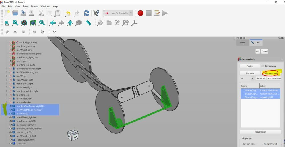
Then you can select the face where you want some tabs for the finger joint.

You can choose how many tabs you want on each face. I choose 1 for the smallest one to 3 for the longest.
And finally, I clicked on the first part, I added the parameters of my Laser Cutter Machine. Regarding what I found in the joint clearance section](/2023/labs/kamplintfort/students/dorian-somers/weekly-assignments/week03#joint-clearance), I chose for the laser diameter (kerf) and for the slot width tolerance. Then I hit OK.

A new part has been created called MultiJoin with all the tabs made and an offset for the kerf and clearance. I selected the parts in the MultiJoin and click on the Export button.
Once the operation is done, the link between the original parts has been lost. So if you need to change some parameters I'll need to redo the last steps.

It creates a new FreeCAD file from where I can export the 2D DXFs files.
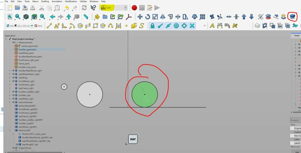
For the other parts, I need to flatten the face, so I went to the Draft Workbench and use the Shape 2D View function. Being perpendicular to the face, I select the face and then project it on the XY plane with the function.
When it's done I can select all the Shape2DView and Export them (Files > Export).

Scale model assembly
In the end, I had two DXF files: mockup-laser-frame.dxf and mockup-laser-frame-rear.dxf. The first DXF has been cut with the offset from the joint clearance. But for the second one, the LCInterlocking workbench has already set the right offset.
I had to be careful to set the offset to the inner or outer shape of the piece.
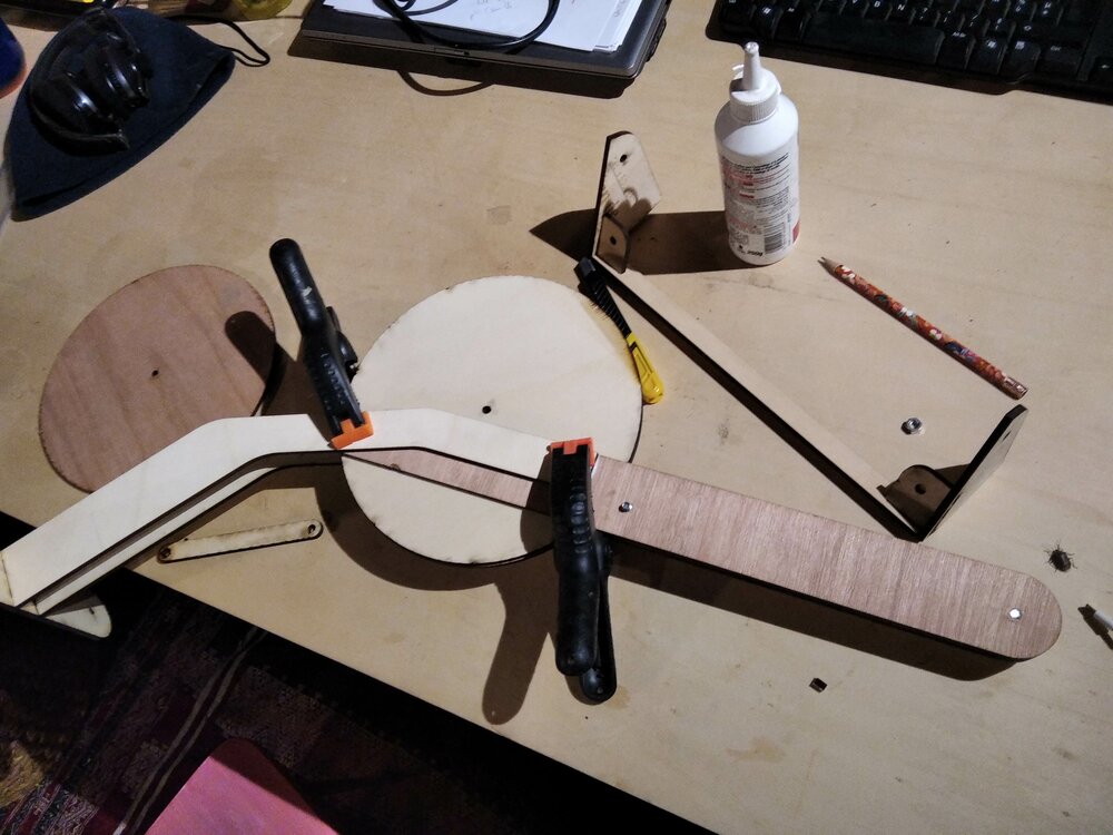
Notes: Disepointed by the LCInterlocking automatic offset, some joints was prefect, but not all of them. I made a mistake on my model. I actually draw the scale model before doing the snap-fit joint tests. I forget to change the parameters in the scale model. So one of my snap-fit joint broke. I had to glue it. (I saw it too late to recut a new piece).
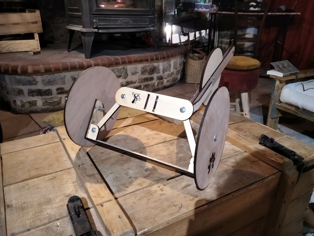
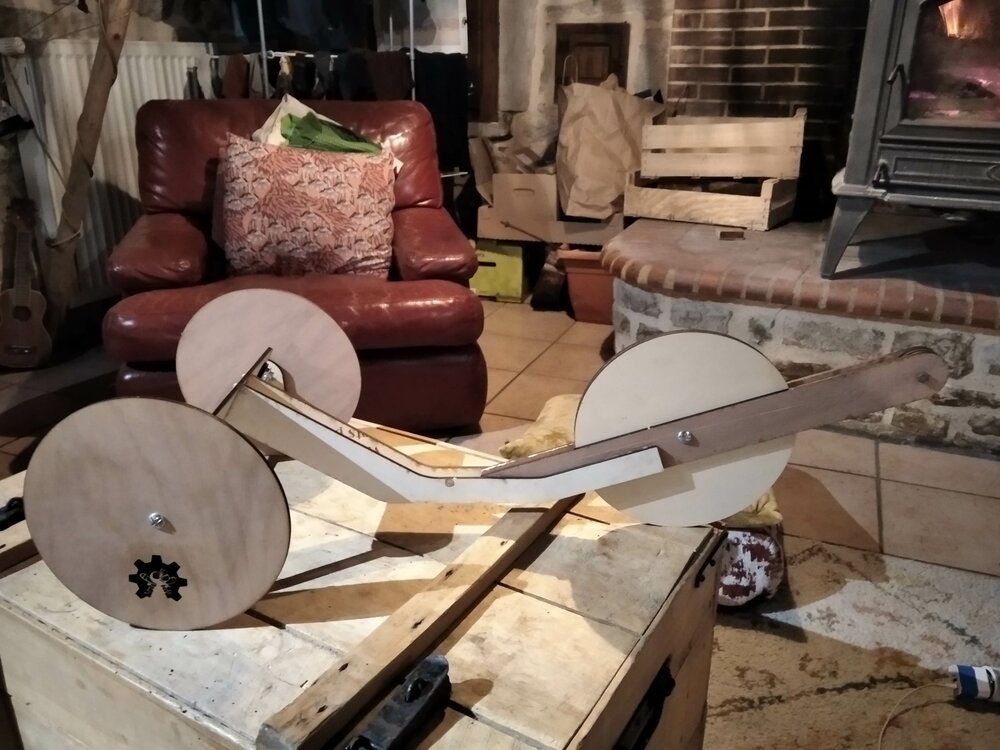
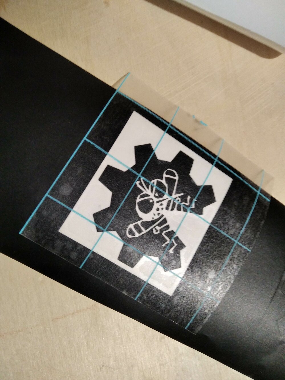
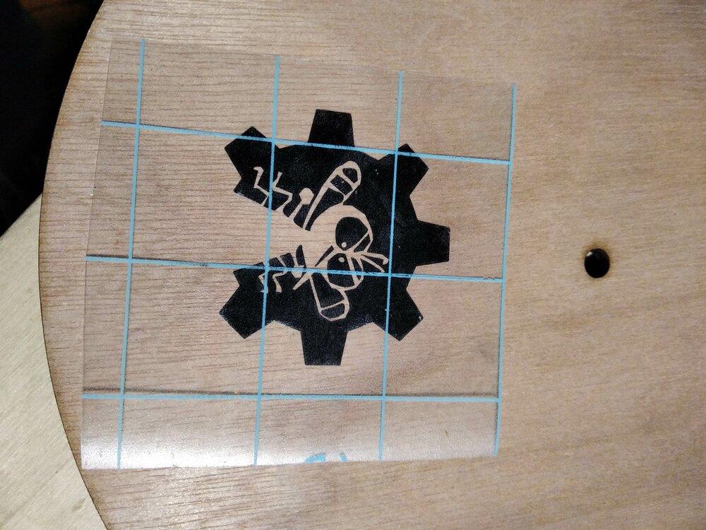
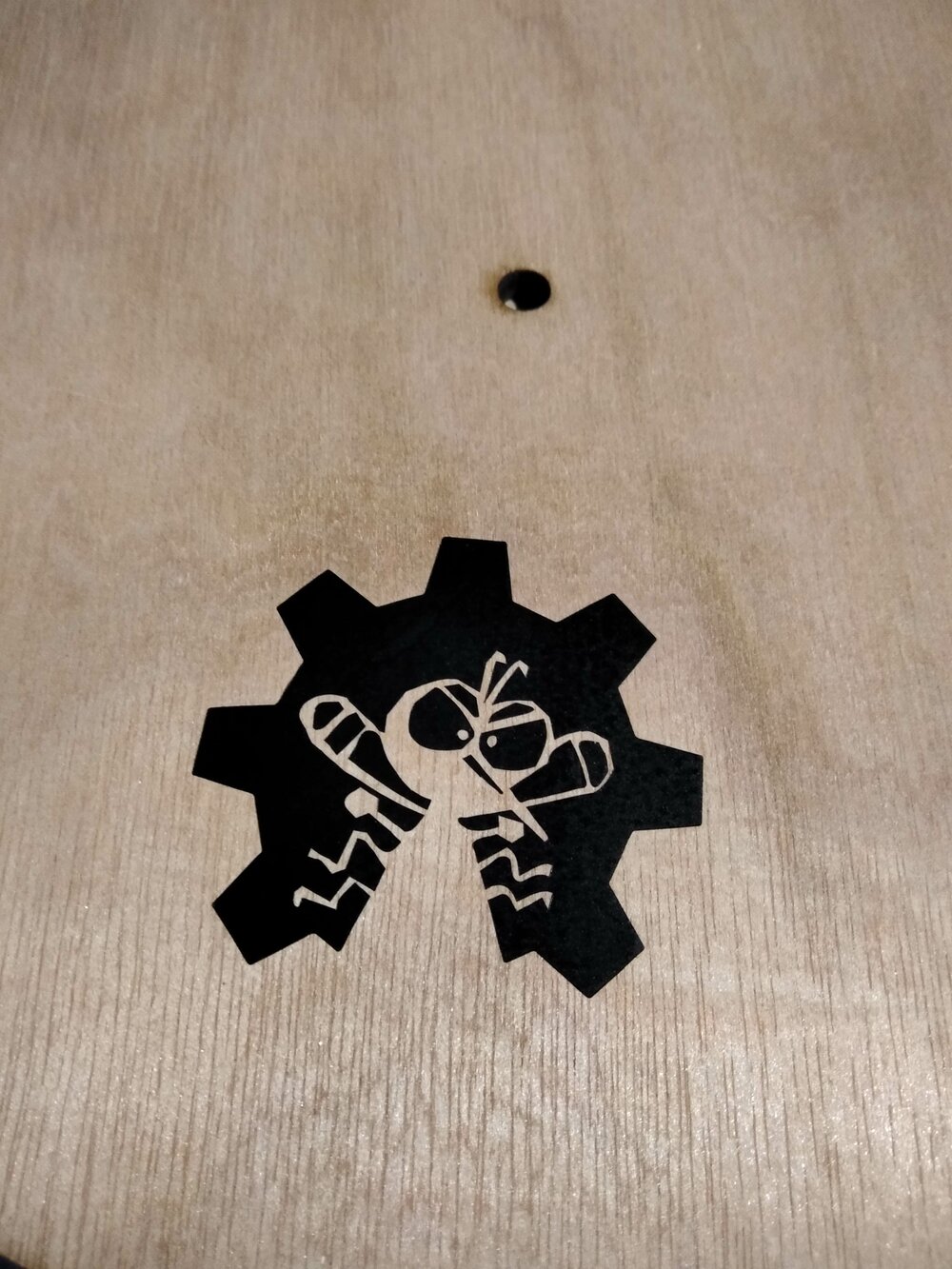
Vinyl cutting
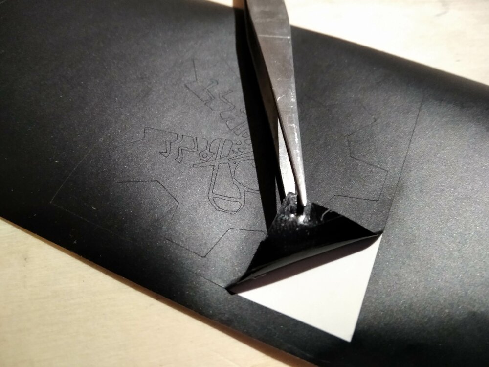
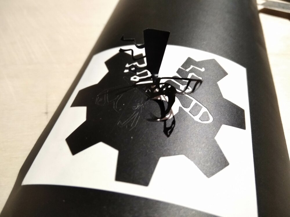
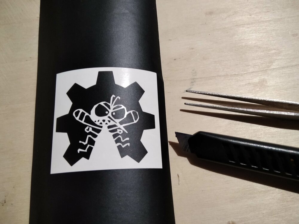
If you look at the scale model there is a vinyl mosquito. For that, I used the plotter of the Fablab (Graphtec CE6000). I decide to transfer the logo of the OpenSource Hardware Mosquito Project on the scale model to put at the rear of the trike.
![]()
I imported the vector logo in DXF in Graphtec Studio. I chose a size that pleased me.
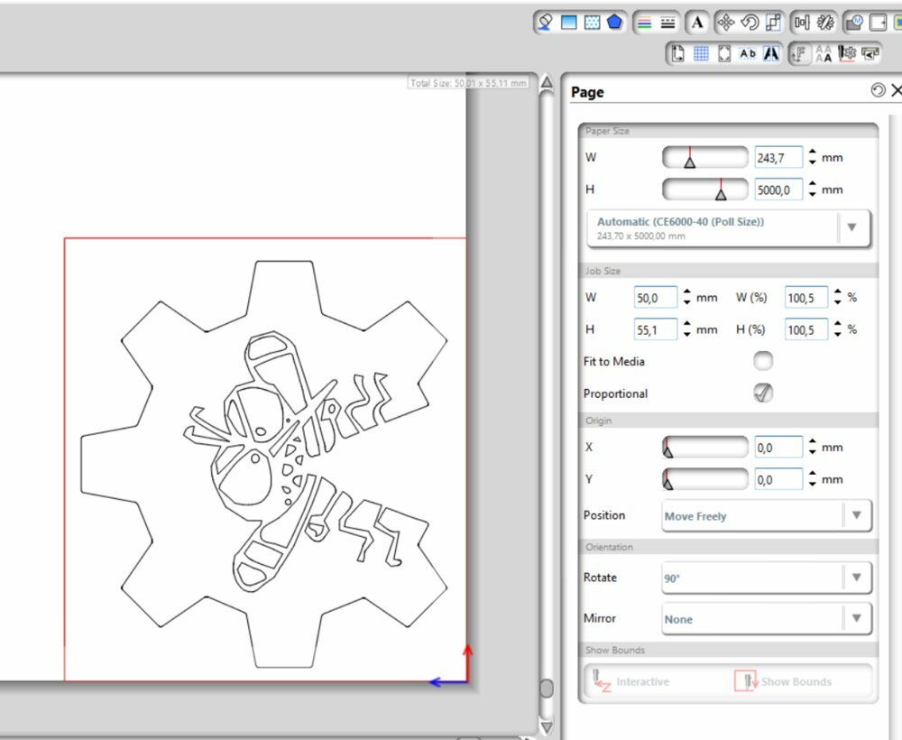
With a force and speed set to and *30cm/s$ I send the draw to the machine
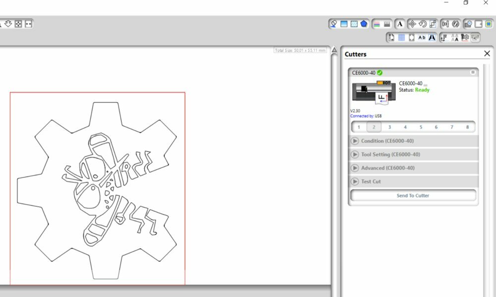
I had to redo it as I stupidly cut the logo on the test force of the machine.
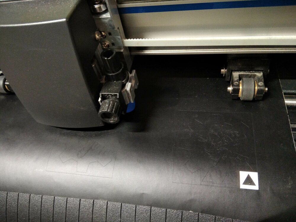
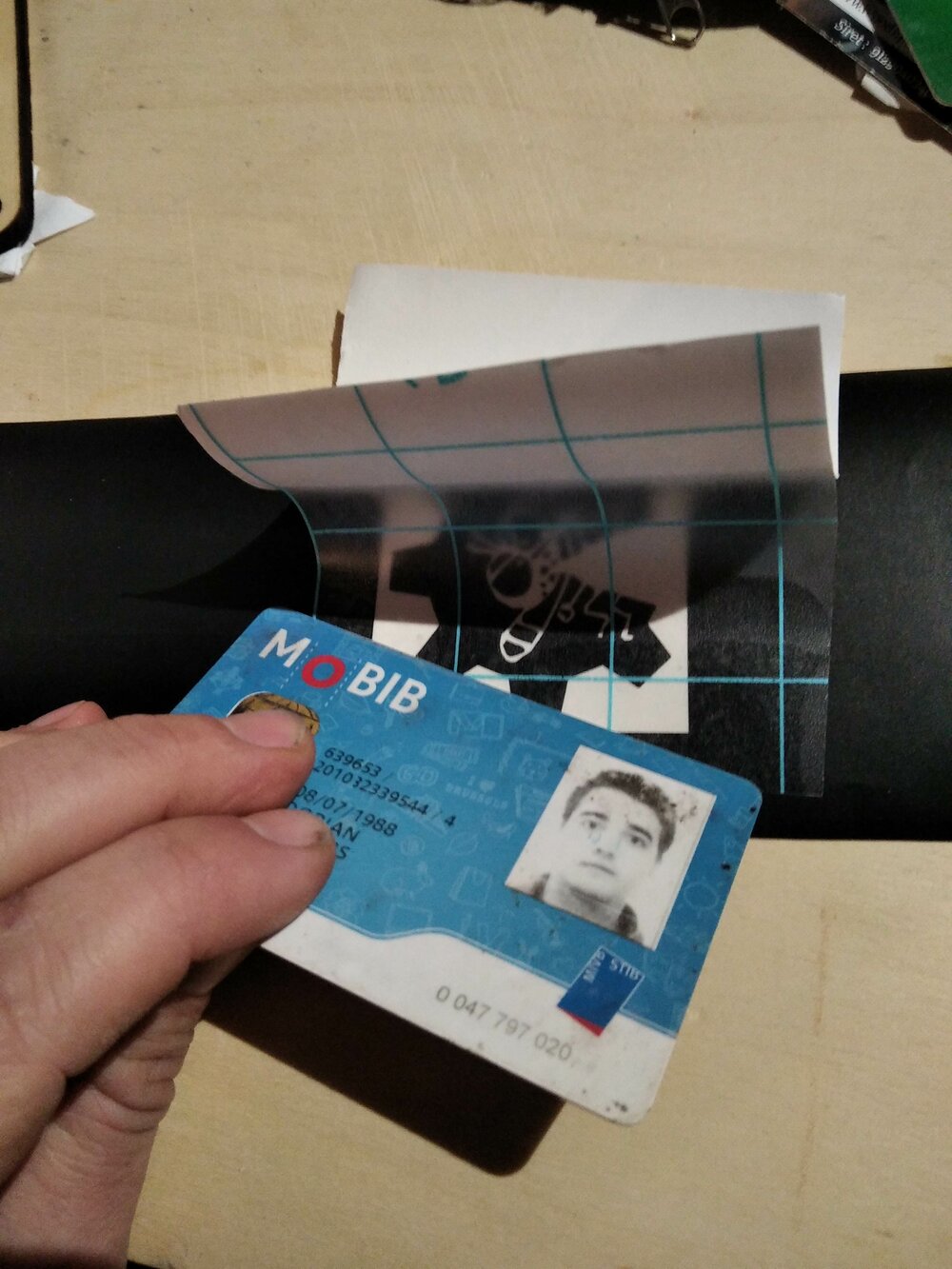
I tore off the vinyl with a paper transfer.
Update 12/03/2023
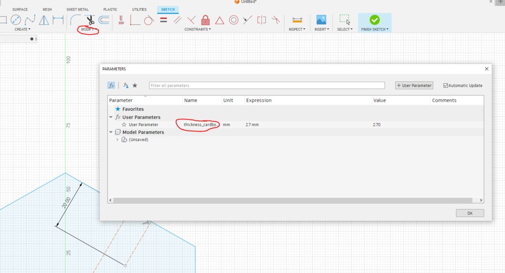
Press-kit
As I misunderstood the assignment with my scale model, here is a small press kit. I decided to design the 2D drawing on Fusion 360. So first, let's declare a variable of the cardboard's thickness.
I use the mirror function to create the cardboard slot.
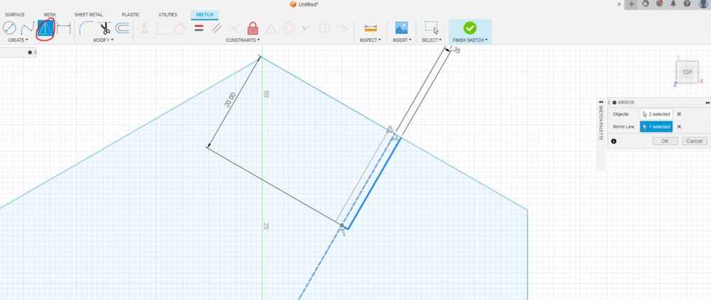
I added a chamfer, to make it easier to put the cardboard polygons together.

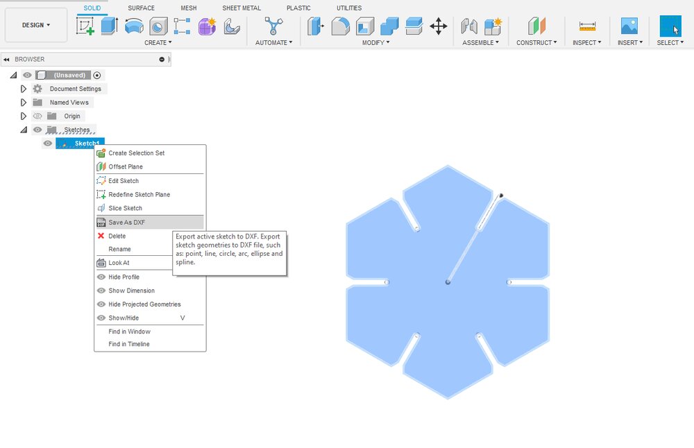
With the Circular pattern tool, I created all the other slots.

I then trimmed (T) the openings of the slots and exported the DXF file.
In the LaserCut software, I imported the DXF and duplicate the shape with the Rectangular Pattern, called Copys in the software.
I then sent the job to the laser with the right parameters. And here is the results:

Files
Here are the CAD files for the week.