Output Devices
Group assignment:
- Measure the power consumption of an output device.
- Document your work on the group work page and reflect on your individual page what you learned.
Individual assignment:
- Add an output device to a microcontroller board you've designed and program it to do something.
Pilot a servomotor
On the board of the previous week, I've put a 3-pin connector with 5V, GND and a digital pin. Perfect to test how to pilot a small servomotor.
I have a SM-S2309S micro servomotor. The pin I can use to control it is the D0.

So I connected the servo-motor to my board and then try with this code from this tutorial
#include <Servo.h>

Servo myservo;  // create servo object to control a servo
// twelve servo objects can be created on most boards

int pos = 0;    // variable to store the servo position

void setup() {
  myservo.attach(D0);  // attaches the servo on pin D0 to the servo object
}

void loop() {
  for (pos = 0; pos <= 180; pos += 1) { // goes from 0 degrees to 180 degrees
    // in steps of 1 degree
    myservo.write(pos);              // tell servo to go to position in variable 'pos'
    delay(15);                       // waits 15ms for the servo to reach the position
  }
  for (pos = 180; pos >= 0; pos -= 1) { // goes from 180 degrees to 0 degrees
    myservo.write(pos);              // tell servo to go to position in variable 'pos'
    delay(15);                       // waits 15ms for the servo to reach the position
  }
}
But actually, the Servo.h Library is not made for ESP32C3 architecture so it didn't compile.
So I added this Library for ESP32 and this time it compiles. But the servo doesn't move. So I checked the pin with a multimeter to look if I have 5V and the Ground. And I have it!
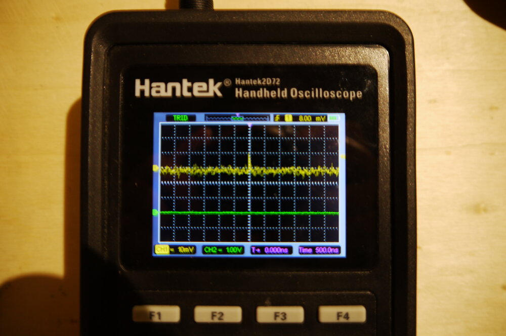
So maybe it's the D0 signal ? So first I connected the Oscilloscope. I have a noisy signal.
So I push my test signal from the Wee6 to see if the D0 pin works properly. And it works! I have the signal on the oscilloscope. So maybe is in the code. I went on the repo of the Library if there were any settings I should have added. Then I saw this issue and it looks like the ESP32C3 is not compatible yet with this library. I found [this post on Arduino's forum that tell us to use the AnalogWrite Library for ESP32.
So I rearrange this code for my pin like this:
#include <pwmWrite.h>

Pwm pwm = Pwm();

const int servoPin = D0;

void setup() {
}

void loop() {
  int position;  // position in degrees
  for (position = 0; position <= 180; position += 30) {
    pwm.writeServo(servoPin, position);
    delay(1000);
  }
}
Now I have a PWM signal.
We can see on the Oscilloscope that the period of the signal is so the frequency is . Moving the pin, I saw that the connection wasn't great enough, so I switch to an SG90 servo motor. But the pins are not in the same order so I used some cable to connect the servo correctly.
I add some buttonRead to turn the servo in one direction or to the other.
#include <pwmWrite.h>

Pwm pwm = Pwm();

const int servoPin = D0;
const int buttonLeft = D1;
const int buttonRight = D2;

int position = 0;  // position in degrees


void setup() {
  pinMode(buttonLeft, INPUT);
  pinMode(buttonRight, INPUT);
  Serial.begin(9600);
}

void loop() {
  if (digitalRead(buttonLeft) == HIGH) {
    position +=30;
    Serial.print("left CW");
    Serial.println(position);
    pwm.writeServo(servoPin, position);


  }
  if (digitalRead(buttonRight) == HIGH) {
    position -=30;
    Serial.print("right CCW");
    Serial.println(position);
    pwm.writeServo(servoPin, position);


  }
  delay(1000);
}
Here is the video
Power consumption
I still have the UM34C power test. It can actually be connected by Bluetooth, and I found a Desktop App to analyze the result on my computer.
So here are the results when the servomotor is plug-in.

I can see clearly when I push the button to move the servo. It can raise the current to .
OLED Screen through I²C
I bought some small OLED display 0,96". They connect with the I2C signal protocol.
On my board, a have 4 pins on the front to power and speak with an OLED display.

Now let's connect it and display something. First I had to install the library U to help me communicate with the display.
So first I select in the Arduino IDE the GraphicTest example.
In the code, I uncommented this line to be used by the ESP32C3 as I read in the wiki of the XIAO ESP32C3
// U8G2_SSD1306_128X64_NONAME_F_SW_I2C u8g2(U8G2_R0, /* clock=*/ SCL, /* data=*/ SDA, /* reset=*/ U8X8_PIN_NONE);
And here we are, it's working!
I would love to try to show the Mosquito OS logo on the screen. So first I edit it to be 128x64 pixels.

Then I had to convert it to XBM. I use an online converter to do it. Then I take this example and just change the XBM string by mine.
Fun fact, I try to take a picture, but the frequency of the screen is too low for my camera, so I only have a part of the picture.
![]()
So here is a video:
Stepper motor
I have a 28BYJ-48 stepper motor. It's a small stepper motor that does not draw a lot of current (~250mA) so I should be able to drive and power it with the board (but it's not recommended as it can put some noise signals on the board). I also have a ULN2003 motor driver.
I found a nice tutorial with this stepper motor. I'll need 4 PWM pins, so I'll use the ones that were on the board for the SPI signal. I send this code on the board :
//Includes the Arduino Stepper Library
#include <Stepper.h>

// Defines the number of steps per rotation
const int stepsPerRevolution = 2038;

// Creates an instance of stepper class
// Pins entered in sequence IN1-IN3-IN2-IN4 for proper step sequence
Stepper myStepper = Stepper(stepsPerRevolution, D10, D9, D8, D7);

void setup() {
    // Nothing to do (Stepper Library sets pins as outputs)
}

void loop() {
    // Rotate CW slowly at 5 RPM
    myStepper.setSpeed(5);
    myStepper.step(stepsPerRevolution);
    delay(1000);

    // Rotate CCW quickly at 10 RPM
    myStepper.setSpeed(10);
    myStepper.step(-stepsPerRevolution);
    delay(1000);
}
The stepper motor vibrated but didn't turn. So I checked with the multimeter but all the tracks work correctly. So I check the signal with an oscilloscope.
As I can measure only two channels at a time.
Here are the motor Pins 1 and 2.

And here are the pins 3 and 4.

I can already see that it doesn't fit.
I recheck the wires, but they are connected in the right order.
I decided to change to another library: AccelStepper. And use the AFMotor_ConstantSpeed example. But I had the same problem.
I found this diagram about the right order to run the pins motors.

source bluetin.io
So I put a really low speed with myStepper.setSpeed(200);. After that, it was so slow, that I can just have a look at the led turning red on the driver board and comparing with the image of the Phase Sequence.
I can see that the B and C look reverse. And that doesn't make any sense... But when I switch the wires, it works. So I run this example from the library that accelerates and decelerates the motor.
// Include the AccelStepper Library
#include <AccelStepper.h>

// Define step constant
#define MotorInterfaceType 4

// Creates an instance
// Pins entered in sequence IN1-IN3-IN2-IN4 for proper step sequence
AccelStepper myStepper(MotorInterfaceType, D10, D9, D8, D7);

void setup() {
  // set the maximum speed, acceleration factor,
  // initial speed and the target position
  myStepper.setMaxSpeed(1000.0);
  myStepper.setAcceleration(50.0);
  myStepper.setSpeed(200);
  myStepper.moveTo(2038);
}

void loop() {
  // Change direction once the motor reaches target position
  if (myStepper.distanceToGo() == 0)
    myStepper.moveTo(-myStepper.currentPosition());

  // Move the motor one step
  myStepper.run();
}
Here is a video.
Power consumption
Still with this code, I plug the UM34C to look at the current.

We can see the acceleration and deceleration of the motor. The motor consumes around 1,6 watts.
That's it for this week. I had some problems at my work, so I could do more this week. I'm a bit frustrated, I would love to play more with the display and the step motor. For the last one, I know next week of the Machine Design, I'll have the opportunity to play again with step motors.
Files
Here are the files for the week