Networking & Communications
Group assignment:
- Send a message between two projects
- Document your work to the group work page and reflect on your individual page what you learned
Individual assignment:
- design, build, and connect wired or wireless node(s) with network or bus addresses
I²C Arduino between ESP32C3
For the Design Machine week, we use a CNC shield connected to an Arduino Uno. As it's handy for piloting stepper motors, the Arduino Uno is old and limited.

source forum.arduino.cc
On the Shield, there is the opportunity to plug in I2C wires to speak to the microcontroller. So the idea is to be able to connect an ESP32C3 so I can connect with bluetooth for example and launch some G-Code. Unfortunately, GRBL doesn't support I2C for the moment1. But I can still try to make an Arduino communicate with an ESP32C3.
Following this tutorial I decided to connect the arduino and the ESP32C3.
My Master will be the ESP32C3. So here is the code I put in it, it's just sending a counter and asking for the Receiver's counter.
// Arduino Sender sketch

#include <Wire.h>

byte i2c_rcv;               // data received from I2C bus
int counter;

void setup(){
    Wire.begin(); // join I2C bus as the master
    Serial.begin(9600);
    // initialize global variables
    i2c_rcv = 0;
  counter = 0;
  Serial.println("Sender setup");
}

void loop(){
    Wire.beginTransmission(0x08); // informs the bus that we will be sending data to slave device 8 (0x08)
    Wire.write(counter);        // send value_pot
    Wire.endTransmission();       // informs the bus and the slave device that we have finished sending data
  Serial.print("Sender sent: ");
  Serial.println(counter);
  counter++;
    Wire.requestFrom(0x08, 1);    // request potentiometer position from slave 0x08
    if(Wire.available()) {        // read response from slave 0x08
        i2c_rcv = Wire.read();
    Serial.print("Sender received: ");
    Serial.println(i2c_rcv);
    }
  delay(5000);
}
And now, In the Arduino Uno, I put the following code. The only thing that it has is using the built-in LED to show the communication (There is none in the XIAO ESP32C3).
// Arduino Receiver sketch

#include <Wire.h>

byte i2c_rcv;               // data received from I2C bus
unsigned long time_start;   // start time in mSec
int stat_LED;               // status of LED: 1 = ON, 0 = OFF
byte counter;               // counnter position

void setup(){
    Wire.begin(0x08);           // join I2C bus as Slave with address 0x08
    Serial.begin(9600);
    // event handler initializations
    Wire.onReceive(dataRcv);    // register an event handler for received data
    Wire.onRequest(dataRqst);   // register an event handler for data requests

    // initialize global variables
    i2c_rcv = 255;
    time_start = millis();
    stat_LED = 0;

    pinMode(13, OUTPUT);        // set pin 13 mode to output
  Serial.println("Receiver setup");
}

void loop(){

    // blink logic code
  if((millis() - time_start) > (1000 * (float)(i2c_rcv/255))) {
        stat_LED = !stat_LED;
        time_start = millis();
    }
    digitalWrite(13, stat_LED);
}

//received data handler function
void dataRcv(int numBytes){
    while(Wire.available()) {   // read all bytes received
        i2c_rcv = Wire.read();
      Serial.print("Receiver received: ");
      Serial.println(i2c_rcv);
    }
}

// requests data handler function
void dataRqst(){
    Wire.write(counter); // send potentiometer position
  Serial.print("Receiver sent: ");
  Serial.println(counter);
  counter++;
}
source electronicwings.com
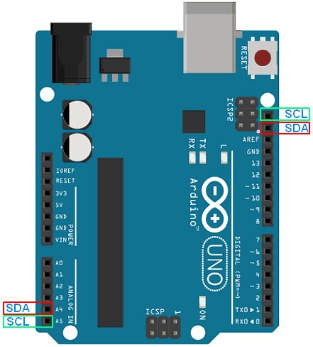
Following the Pinout diagram of the XIAO and the one for the Arduino Uno, I connected them.
Here we can see the counter passing from one to the other. And the small TX LED of the Arduino blinks every 5 seconds.
LoRA
Design a module
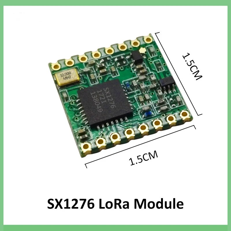
source AliExpress
I bought two small LoRa modules to play with. But the pin holes a not a classic 2.54 space. So if I want to use then I need to redesign a module around it. So I will design it in KiCAD.

So first I need the footprint of the module. I found first this part in SnapEDA that was looking the same. But after opening it on the Footprint Editor in KiCAD, the dimensions didn't match (the height was too big).
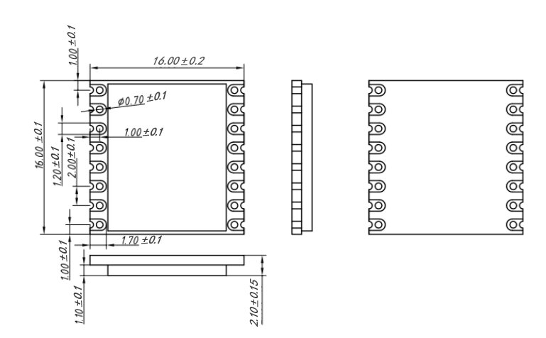
source nicerf.com
So I thought about designing my own footprint in KiCAD with the right dimension I found online. But still looking at the SnapEDA website, I finally found the right footprint here. My module seems to be super close to a RFM95W 868 module.
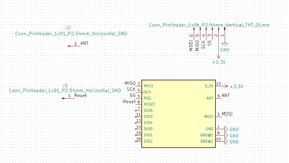
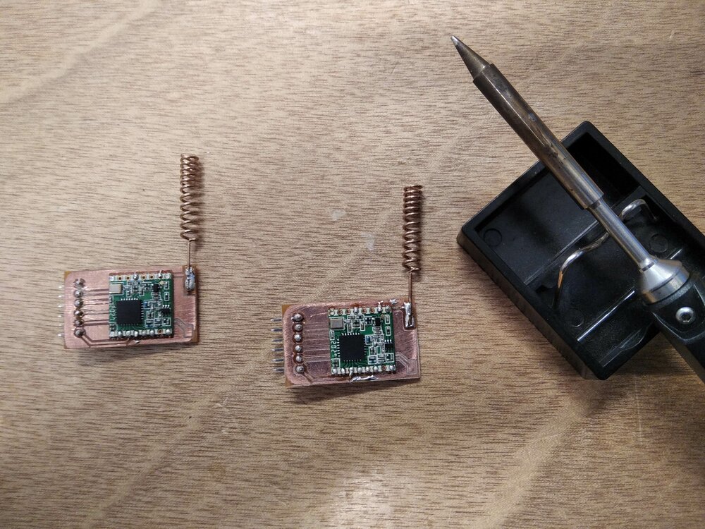
Once imported the Simbolic library, I could create a schematic of the module. I wanted 6 pins to connect with SPI and power the module, a pin for reset if needed and a big pin where I'll solder the antenna.

Then I try to make something compact. Most of the tracks going behind the LoRa board.
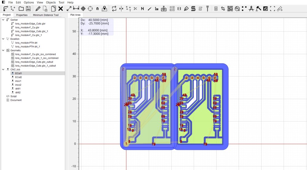
Once the Gerber files were generated in KiCAD, I then used FlatCAM to generate the G-Code. Here I see the utility to document everything... I had already forgotten most of the process, but I had just looked at my week 8 (more than a month ago).
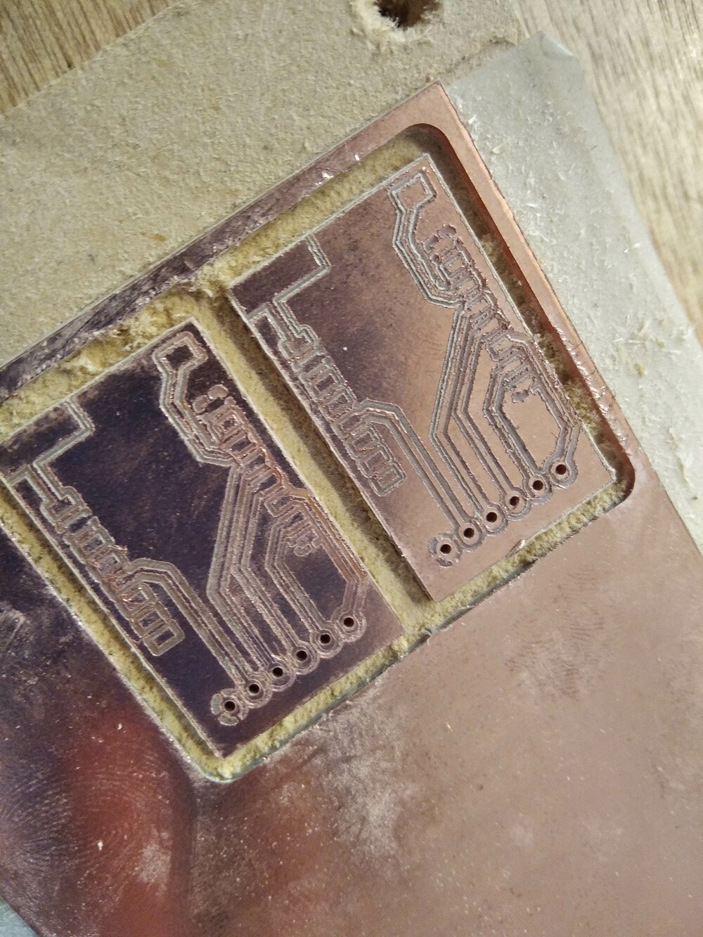
As for week 8, the result is not super nice, but it should be enough for the test purpose.
here
Play with LoRa
Normally, to be able to talk to LoRa with this module this LoRa library for Arduino IDE should work.
I connected one module on an XIAO ESP32C3, it will be the Sender with this code:
#include <SPI.h>
#include <LoRa.h>

int counter = 0;

void setup() {
  Serial.begin(115200);
 while (!Serial);

 Serial.println("LoRa Sender");
 LoRa.setPins(SS);
 if (!LoRa.begin(868E6)) {
   Serial.println("Starting LoRa failed!");
   while (1);
 }
}

void loop() {
  Serial.print("Sending packet: ");
  Serial.println(counter);

  // send packet
  LoRa.beginPacket();
  LoRa.print("hello ");
  LoRa.print(counter);
  LoRa.endPacket();

  counter++;

  delay(5000);
}
And here is the code for the Receiver:
#include <SPI.h>
#include <LoRa.h>

void setup() {
  Serial.begin(115200);
  while (!Serial);
  delay(5000);
  Serial.println("LoRa Receiver");
  LoRa.setPins(D3);
  if (!LoRa.begin(868E6)) {
    Serial.println("Starting LoRa failed!");
    while (1);
  }
}

void loop() {
  // try to parse packet
  int packetSize = LoRa.parsePacket();
  if (packetSize) {
    // received a packet
    Serial.print("Received packet '");

    // read packet
    while (LoRa.available()) {
      Serial.print((char)LoRa.read());
    }

    // print RSSI of packet
    Serial.print("' with RSSI ");
    Serial.println(LoRa.packetRssi());
  }
}
But then I wouldn't be able to download the Receiver code into my board from week 8. When plug in the module with SPI on my board, I add some trouble to go on download mode, it seems to be related to the GPIO 8 and 9 that are used for the SPI communication.
So I switched to my XIAO SAMD21 board, and it's working!
FM alert
The idea behind this is that a trike is low on the road, so difficult to be seen. Especially with those new trendy SUV cars. Where I live, there are really few FM radios because I'm in the countryside, so maybe I could transmit on a 50meter range an FM radio signal that says "be careful there is a tricycle in front of you" on each local popular FM frequency.
It's not allowed in every country to play with an FM radio signal. Please check this before doing that. Here I'll do it at home, for a test purpose.
Understanding I2C
The FMTX.h library for the module is old and doesn't compile for the ESP3C3. The main issue seems to deal with how it handles I2C communication.
So first I connected the module and try to read some information from it.
So first I need to find its I2C address, so I launch this code from this article()
/*********
  Rui Santos
  Complete project details at https://randomnerdtutorials.com
*********/

#include <Wire.h>

void setup() {
  Wire.begin();
  Serial.begin(115200);
  Serial.println("\nI2C Scanner");
}

void loop() {
  byte error, address;
  int nDevices;
  Serial.println("Scanning...");
  nDevices = 0;
  for(address = 1; address < 127; address++ ) {
    Wire.beginTransmission(address);
    error = Wire.endTransmission();
    if (error == 0) {
      Serial.print("I2C device found at address 0x");
      if (address<16) {
        Serial.print("0");
      }
      Serial.println(address,HEX);
      nDevices++;
    }
    else if (error==4) {
      Serial.print("Unknow error at address 0x");
      if (address<16) {
        Serial.print("0");
      }
      Serial.println(address,HEX);
    }
  }
  if (nDevices == 0) {
    Serial.println("No I2C devices found\n");
  }
  else {
    Serial.println("done\n");
  }
  delay(5000);
}
And here is what he found
18:25:48.737 -> Scanning...
18:25:48.785 -> I2C device found at address 0x3E
18:25:49.766 -> done

I also found it in the datasheet of the Digital Stereo FM Transmitter.
I want to read some info from the module, so following the doc I flash this code:
#include <Wire.h>

void setup() {
  Wire.begin();             // Join I2C bus (address is optional for controller device)
  Serial.begin(9600);       // Start serial for output
}

void loop() {
    Wire.requestFrom(0x3E, 6);    // Request 6 bytes from slave device 0x3E

    // Slave may send less than requested
    while(Wire.available()) {
        char c = Wire.read();    // Receive a byte as character
        Serial.println(c);       // Print the character
    }

    delay(500);
}
I get this (some text..)
18:29:23.579 -> \⸮@\⸮@
I could Refer to Ascii values, but to be sure to have all the information I just changed this line to get directly the HEX format.
Serial.println(c, HEX);
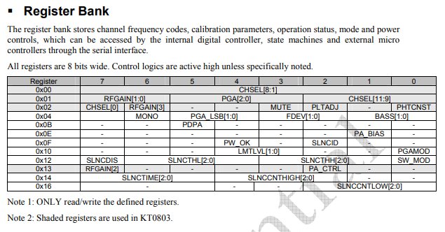
So I get those 5 values are 0x5C, 0xC3, 0x40, 0x0 and 0x4. After some reading in the datasheet. Those values seem to be the ones stored in the Register Bank of the Transmitter module.

I need to change the third value as I live in Europe. So I need to send this 0x41 data to the register's address 0x02.
But first I need to be able to read some data from an address of the register with Wire.h
So I try this (Thanks ChatGPT !!!):
void loop() {
    Wire.beginTransmission(0x3E); // transmit to slave, the FMTX
    Wire.write(0x01);             // register 0x01
    Wire.endTransmission(false);  // allowing to read after the write function
    Wire.requestFrom(0x3E, 1);    // Request 1 bytes from slave device
    byte c = Wire.read();         // Receive a byte as character
    Serial.println(c, HEX);       // Print the character
    Wire.endTransmission();

    delay(3000);
}
Now that I can read data from any register I need to write to it, so here is the new function:
void fmtx_write_reg(u8 reg, u8 dt)
{
    Wire.beginTransmission(FMTX_ADDR);
    Wire.write(reg);
    Wire.write(dt);
    Wire.endTransmission();
}
So I edit the Library, and it's now compatible with my XIAO ESP32C3!
I get what I want on the terminal. But for now, the board doesn't work. I'll try to make it work later on.
Files
Here are the files of the week.
- Cfr. this issue: https://github.com/grbl/grbl/issues/254↩