Computer-Aided Design
- Modeled experimental objects/part of a possible project in 2D and 3D software
- Shown how you did it with words/images/screenshots
- Included your original design files
Spiral Goals
- Install FreeCAD's Realthunder Link (Assignment)
- 3D model a mockup for the Final Project (Assignment)
- Create 2D vector drawings for the website (Assignment)
- Try to assemble the 3D mockup parts with the Assembly 3 workbench (Bonus)
- Try to use OSH Automated Documentation (Bonus)
My CAD stack
I'm a Fusion 360 user for 6 years now. For me is one of the best and easy-to-use CAD software available on the market. But in 2021 they change their license and restricted some features to the paid plan. In terms of free alternatives, FreeCAD looks pretty powerful. In the past, I've tried FreeCAD, but the learning curve is a bit steep. To challenge myself a bit, I'll use as much as I can FreeCAD for the Fab Academy.
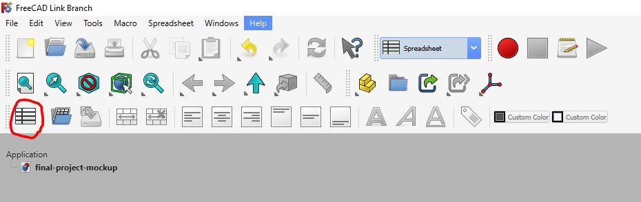
As I've been impressed by Pieter Hijma's project of Open Source Hardware documentation, I've installed the Realthunder fork of FreeCAD, the same as he uses for the OSH Automated Documentation Project.
After I installed FreeCAD Link, I changed some interface customizations following this tutorial, and changed the 3D navigation gesture for the Blender one (Edit > Preferences > Display > Navigation).
For parametric 2D CAD, I usually use the sketch workbench of Fusion 360 or FreeCAD and the DXF export. But I may use LibreCAD or Inkscape for simple vector design.
Designing a parametric 3D mockup
On the trike, a lot of the dimensions can change regarding the size of the driver and other choices, as seen on the geometric page. So the best is to take advantage of the spreadsheet workbench of FreeCAD.
To get familiar with FreeCAD, will first design a simple Mockup of the Final Project.
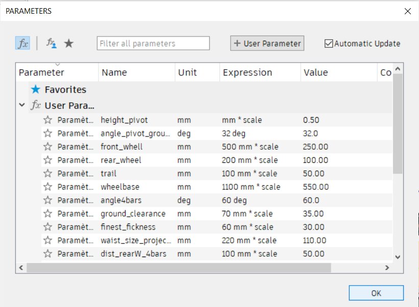
Declare de variables
With the help of a paper sketch and some considerations about the [geometry of the tricycle, I created a spreadsheet.
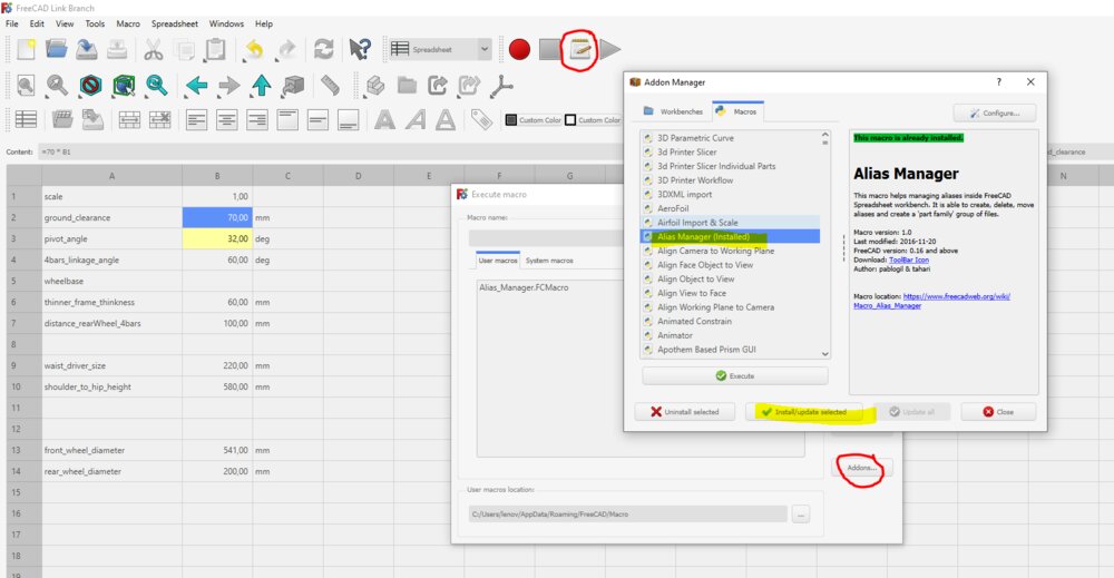
Here are the first variables I declared:
| variable_name | value | unit |
|---|---|---|
| scale | 0.25 | |
| Trike Geometry | ||
| ground_clearance | =70 * $B$1 | mm |
| pivot_angle | 32 | deg |
| fourBars_linkage_angle | 60 | deg |
| wheelbase_length | ||
| frame_minimum_thickness | =60 * $B$1 | mm |
| Body Measuremennt | ||
| waistDriver_size | =220 * $B$1 | mm |
| shoulder_hip_height | =580 * $B$1 | mm |
| Components size | ||
| front_wheel_diameter | =541 * $B$1 | mm |
| rear_wheel_diameter | =200 * $B$1 | mm |
It's a good start, I'll come back later to add new variables when needed. To find all the variables. I've installed this macro to create an alias of the values from the first column. Following this tutorial, you will be able to add a special icon to access the macro.
I decided to change the name of the spreadsheet after drawing the first line add some variables to the constraints. It broke the links, and it took me some time to find the constraints broken, so better to choose de name before starting to use the spreadsheet.
First sketches and construction lines
Once it's done, I've created a new sketch. The first one will be on the XZ-Plane.
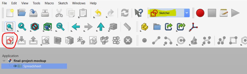
When on the Sketch workbench, I first activated the "construction mode", as my first line will use as reference.

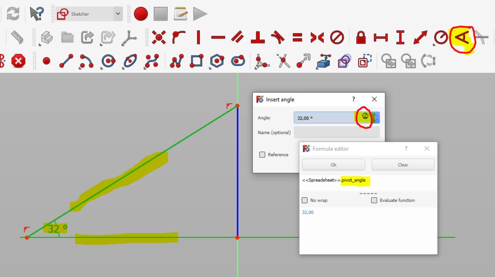
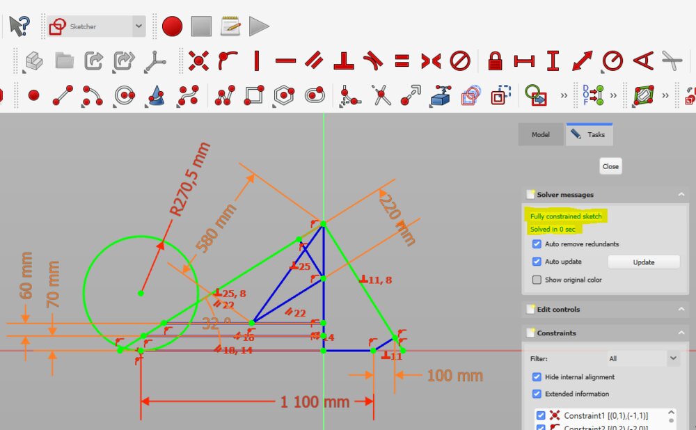
The first constraint have put is the angle between the pivot and the horizontal line.
Then a perpendicular constraint between the pivot and the line representing the 4 bars linkage trapeze.
Then I added future contact of the rear wheels with the ground regarding the distance with the trapeze and with a define wheelbase variable, I drew the circle for the front wheel.
The next step is the construction lines for the seat. So I set a parallel line to the pivot axe for the back of the seat and a horizontal line at the bottom of it.
Once all the drawings have been made, I made sure that on the task panel, it's show "Fully constrained sketch".
It would be nice to have a proper look at this macro to set constraint names to the variable name in the spreadsheet.
4 bars linkage sketch
The next sketch is a bit more tricky as is not on one of the 3 orthogonal planes. I've tried the new "local origin technic". On Part Design workbench, I selected the pivot line from the first sketch and click on create a local coordinate system with Z tangent to the edge selected.
Note: I wanted first to use a datum plane a bit like I'm used to use on Fusion 360 to create a new surface for my sketch, but I didn't succceed to create it in the first place.
Then, with the new Local_CS selected, I can create a new sketch. With the External geometry tool (Sketch > Sketcher geometries > External geometry, shortcut: x,x) I have imported the line representing the 4 bars linkage trapeze from the first sketch. I've imported also the point between the distance line rearWheel-trapeze.
From there, I faced a bug that I couldn't be able to understand. I was trying to set a new Local origin for the rear wheel plane. Doing it, I've movef some objects on the tree, and something broke.
Re-do everything
I saved my FreeCAD file, but from the start, I didn't commit anything. FreeCAD has no version control built-in system, but GIT can do it. So, Ok, let's restart. I will be able to fix in the same time an other mistake I made:
When choosing the XZ Plane for the first sketch, I selected XZ Plane as the reference. But it's named "Front". The Vertical cross-sectional sketch represents the right face of the trike, not the front.
At least, I have all my variables. I'll clean the nomenclature. camelCase for the part, and snake_case for the characteristic of the part, and I can combine both of course.
I've re-done it, but with Datum Planes this time, and had the same problem. I discovered what I've done wrong. I've gone directly to the sketch workbench and created a new sketch. But the sketch wasn't attached to any reference. I struggle a lot to attach my sketch to any reference. The best is to create a new sketch from the Part Design workbench. There the new sketch is put in a body with his origin. Hard way to learn, lost hours sketching 3 times the drawing and looking for answers on the internet.
So let's sketch it one last time and git commit all of this.
Build some part out of the sketches
I've started to build some parts out of sketches. In FreeCAD you need one sketch per part you will extrude.
Then I decided to see if all my construction was still linked with my variables. I change the scale, but then some parts moved. It looks like the sketch of some time de datum planes do not stick to the reference I gave them. I think I still use the way Fusion360 works and try to apply this to FreeCAD. But it seems to need much more work ti constrain everything from the start. In Fusion you can easily start from a constraint and chain a lot of lines, part to it. The link will hardly be loose.
I gave up ... (at least for this week)
You can still download the FCStd File 📐 here
Go back to Fusion 360
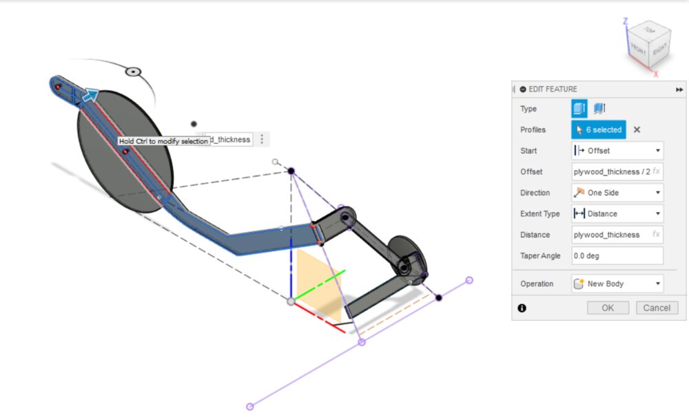
To quickly draw a first mockup of the Final project as it is the assignment of the week, I start back from the first draw I did on Fusion360 to thing about the geometry of the trike. Basicall,y almost all the variables were already set up (MODIFY > Change Parameters).
I thought about a first simple mockup made of plywood cut with a CO2 laser. I did the sketch the same as I would in FreeCAD, just I didn't need to fully constrain all the drawings.
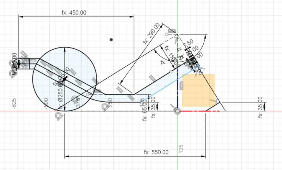
I add some construction planes, like a "plane at angle" for the 4 bars linkage's sketch.
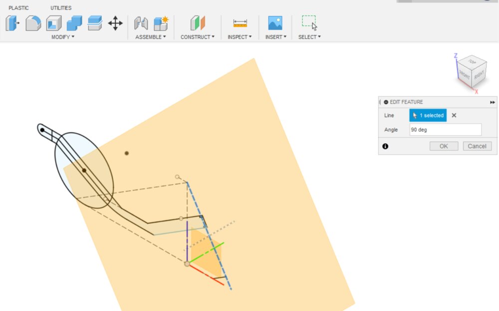
I could reuse onle a few sketches to extrude multiple parts, something you can't do that in FreeCAD.
I design just the right side of the trike and then use de Mirror function to create the left part of it (CREATE > Mirror).
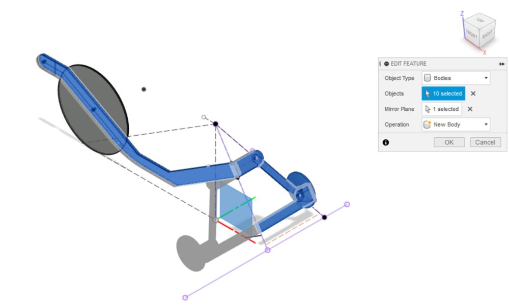
My Fusion360 work is not optimal and has been made too quickly. I'm still not sure if I'm gonna use FreeCAD or Fusion 360. I want to give a chance to FreeCAD. Maybe I will roll back to a more stable version of it. And watch more "way of doing it" tutorials.
Here is my Fusion 360 file📐.
09/02/2023 Update
Drawing some vector icons
On the front page of my website, it'll be great to create my own icon instead of the default docusaurus one. I need two illustrations:
- One for the weekly assignments
- One for the Final project
So let's use Inkscape. For the final project, I use a picture of a previous trike made by the designer of the 4 bars linkages direction. I reshape some form on top of it to simplify the drawing and make an icon out of it. I changed the opacity of the forms to be able to look at the background image.
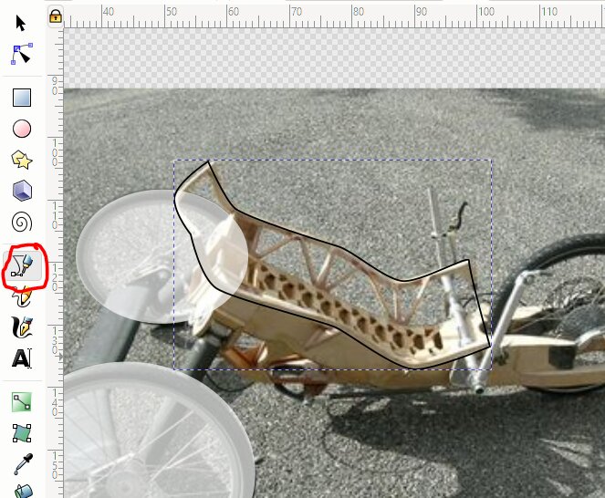
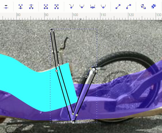
For the more complex forms, I drowned them with the bezier tool.
Sometimes I need to change the property of the node, to change the angle of the curve.
 .
.
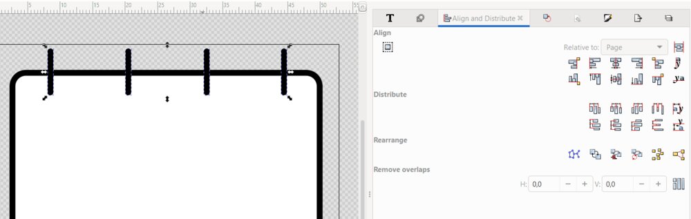
Then I started the icon for the weekly assignment. I shape a round rectangle, then some bars. I aligned them with the Align and Distribute panel.
 .
.
Switch treat selection as a group on or off regarding what you want to arrange. Same for the Relative to option.
Then I draw some boxes for the days of the month/week, some with a letter v in it to represent a "task", an assignment. I put the Vs from Wednesday to Wednesday as it is the rhythm of the Fab Academy. And it was done. (OK, I'm not a Designer pro ^^).
![]() .
.
And here is the Final project icon:
 .
.
You can download them here: icon-final-project.svg and icon-weekly-assignments.svg.
Then I switched the orignal SVG icons of the Home page to the new one in that file: src\components\HomepageFeatures\index.js.
Migrate from Week1
Raster - Compressing images
To compress the images for the website, I've decided to use ImageMagick as a tool to resize and compress all my image. So first I've installed it.
sudo apt install imagemagick
Then a create a command to convert my images, a width of 900 pixels is enough for the website (--resize option) and some parameters of the convert command line flowing that recommendation. As we want to apply those settings to multiple images and replace them, we can use mogrify instead of convert (now magick on the latest version). The \> character in the -resize option means that the image will be resized only if it's larger that the target size ^[Cfr. documentation https://imagemagick.org/Usage/resize/#shrink].
mogrify -resize 900x\> -strip -interlace Plane -quality 85% -format jpg [*.jpg|*.png|...]
You can check the size of the files with the ls -l --block-size=K command, they shouldn't bigger than 150Kb. The next step will be to make a script to automate the image conversion. To be continued...
Video editing
First I edit the video in Kdenlive to trim all the parts I don't need, then render it.
Kdenlive
After I use ffmpeg to compress the video using this command:
ffmpeg -i input.mp4 -c:v libx264 -vf scale=-1:720 -crf 24 -preset slow output.mp4
-iinput file-c:vthe video codex (libx264 is the opensource codex to encode in mp4)-vfa video filter that allows scaling the video (for me 720p is enough for web embedded)-crfthe quality (0the better to50the worst, 24 is good enough)-presetmean the time to compress (slow is better quality)
Just to have an idea of the compression of a video. For the "week 3" assignment, I filmed a joint play of the snap-fit joint. The video from my smartphone was 23Mb, after it been rendered by Kdenlive it was 1,2Mb and after passing by ffmpeg it end at only 313Kb.
Files
Here are the files of the week: