Computer-Controlled Machining
Group assignment:
- Complete your lab's safety training
- Test runout, alignment, fixturing, speeds, feeds, materials and toolpaths for your machine
- Document your work to the group work page and reflect on your individual page what you learned
Individual project
- Make (design+mill+assemble) something big
CNC Router
At the lab we have an Arketype CNC Router, here are the specifications:
| Items | Value |
|---|---|
| Working area | 1300 x 2500 x 100 mm |
| Engraving speed | 0-4000 mm/min |
| Structure | Cast steel |
| Repositioning accuracy | <0,04/ 300mm |
| Collet | ER20 |
| Spindles | 3.2 kW 24000 Rpm |
| Power supply | 220V ± 10%/50 Hz, 110V ± 10%/60 Hz |
| Dimensions | 2000 x 3000 X x 1600 mm |
| Vaccum Table | 380V |
Safety
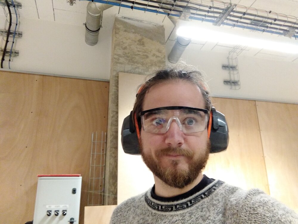
When using the CNC router, we always wear that personal protective equipment: glasses and ear protection.
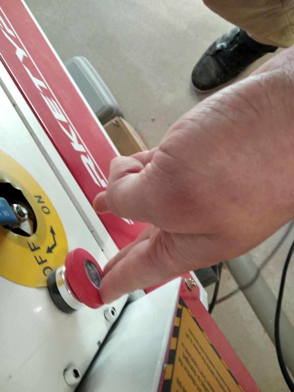
If there is any emergency, I can stop the CNC with the emergency button.
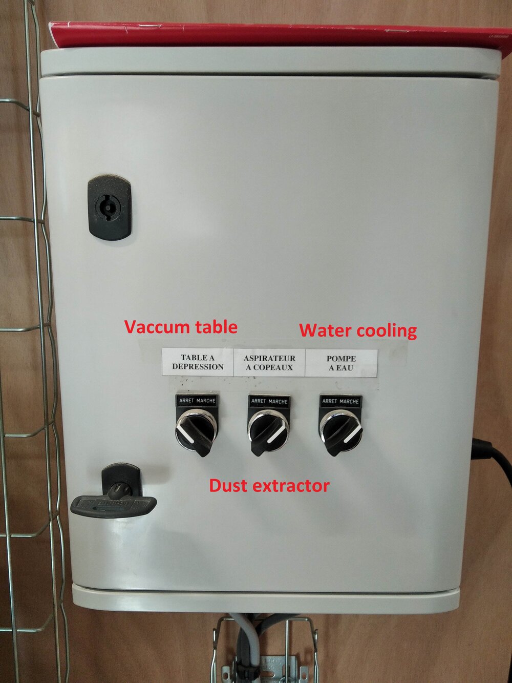
There is also a dust collector, that can be run from the electrical panel, there I can also run the table vacuum.
Fixturing
For Fixturing, we usually use vises on an OSB sacrificial layer. But we can also use the vacuum table. For PCB making we use double tape.
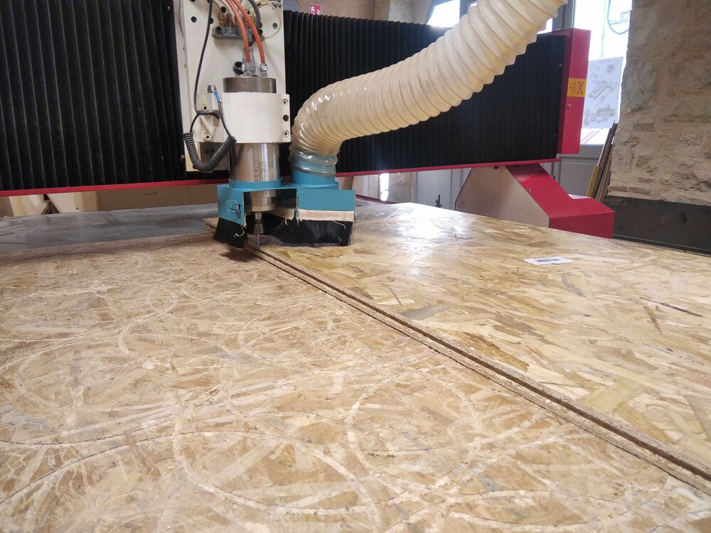
To fix the board, I first a first corner. I go with the Endmill next to it.
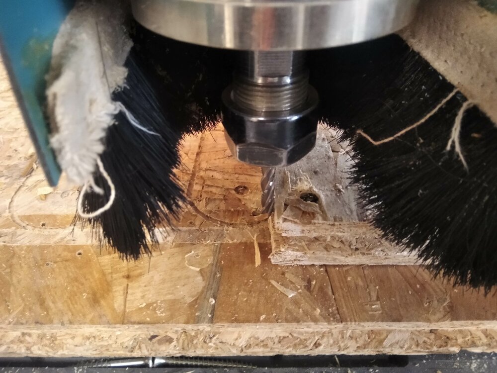
Then I move on the Y axe till the end of the stock and put the stock on the endmill, so I'm sure to be aligned on the Y axe.
spindle and surface speed
Our endmill vendor has a really nice documented page about the spindle, surface, feedrate speeds, and even a spreadsheet to get the different parameters. In Fusion360 we can also get the parameters linked by the formulas.
So first the Spindle speed (). In the vendor documentation, the Surface speed () for wood (Plywood, strong wood and MDF) is around . I plan to use endmills with a diameter () of . So regarding the following equation linking those values:
Here is a table with some for the 3 tools I'll use.
| End-mill diameter | |||
|---|---|---|---|
| Plywood () | 53052 | 26526 | 19894 |
| MDF () | 47746 | 23873 | 17905 |
So for Plywood () with a milling tool the Spindle speed is and for a endmill in MDF () we have an . The maximum spindle speed of our CNC router is , so for the tools, I will use this value and I'll go for for the .
Cutting feedrate
To determine the feedrate (), I need to know the previous spindle speed (), the feed per tooth () and the number of teeth/flutes (). Here the equation:
Here is a table for 3 different tools ( 2-3 flutes and 2 flutes) and the data given but the vendor.
| Endmill diameter | (2 teeth) | (2 teeth) | |
|---|---|---|---|
| Plywood | 2520 (3 teeth) | 4320 | 4000 |
| MDF | 4800 (2 teeth) | 14400 | 16000 |
As the CNC can't go faster than , and actually we try to go even at a lower speed (maximum ), we probably should buy an endmill with only one flute.
Runout and alignment test
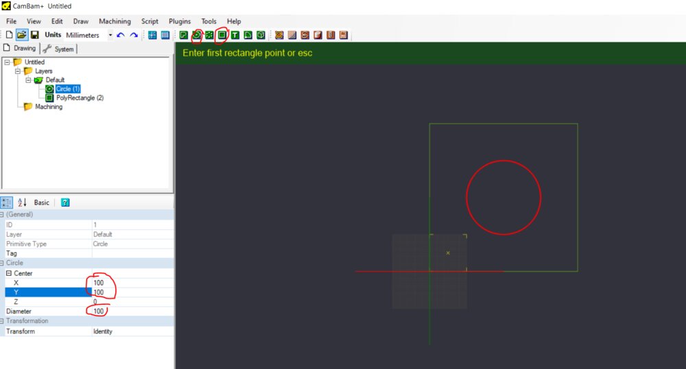
To check the runout and the alignment of the CNC, I'll generate a toolpath of a square and a circle. For that, I'll use the CAM software we use at the lab: CamBam.
I can draw directly in the software a square and a circle. I draw the circle and rectangle in the middle of the screen, then edit their parameters (diameter, width, height and positions) later in the parameters panel on the left.
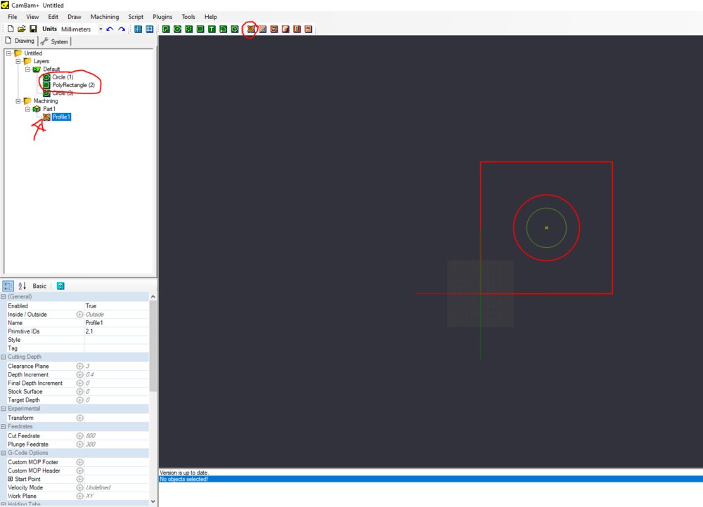
Then I will create the first toolpath for the external paths, I selected them and click on profile.
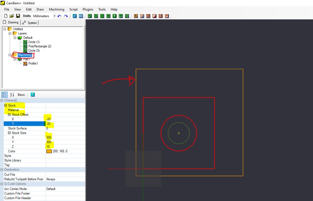
Now I have a Machining folder. There I can create the stock of all the machinings (the stock can also be changed in groups of machinings). I did an offset of to have some room to fix the wood board on the CNC.
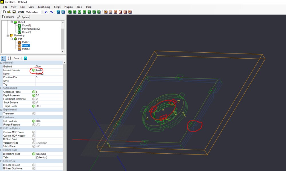
Then I can select the machining and choose the parameters I want. Here I will use a 2 flute flat endmill. So I'll use a cut feedrate of . I like to set a Clearance plane of , so I'm sure the tool will not hit the fixturing vises. I set the target to just a bit more than the sock thickness () so I'm sure it will cut through the sacrificial layer. Depth For the Depth increment, The vendor said in the datasheet of the endmill that for soft materials like plywood/MDF, we can set the depth increment of the cutting equal to the diameter of the tool. As we need to cut and can set a depth increment to so I don't force too much on the tool doing the same number of increments I will have done with an increment of .
For the tabs, I usually set them automatically with CamBam and move them where I want them (not in the corners). I like large triangles with a height of half of the material's thickness.
The cut feedrate and the spindle speed are set on the CNC router, not in the GCode, but I write the information so I can have an estimated toolpath duration.

I did the same of an inner circle, just chose the inside cutting option instead of the outside.
With the Alt key and the mouse, we can move in a 3D view to have a look at the toolpath. It's nice to be sure where the tabs are or if the toolpath I going straight.
I can now generate the Gcode, by selecting the machining folder (otherwise I'll generate only the Gcode for a specific toolpath, it can be useful when there is a different endmill for example).

Then I went to the CNC router and turn it on. On the Digital Signal Processing (DSP) of the CNC controller, it first asks to go HOME.
 source: a member of the fablab
Be careful there is nothing on the table before clicking on go HOME.
I use the technic explained in the Fixturing section to fix my stock.
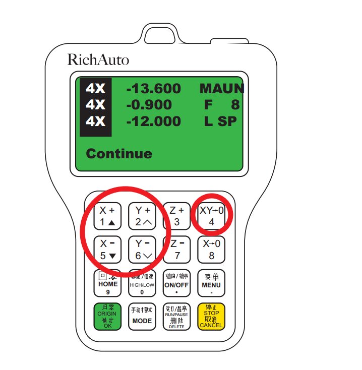
After I put the endmill, I move the tool where I want my origin in X and Y.
 source: a member of the fablab
For the Z origin, I put a piece of paper and move it in Z axis carefully till the paper does not move anymore and set the Z origin.
Then in the DSP I click on RUN/PAUSE and chose UDISK File.
 source: a member of the fablab
I select the cnc-tests.nc file on the list.

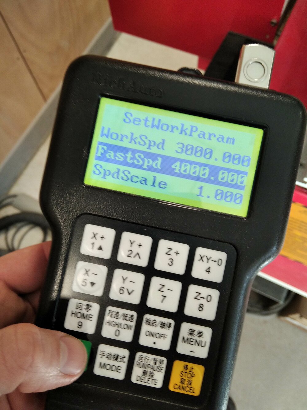
Now I need to choose the cutting feedrate (call WorkSpeed on the DSP). I set it to (by clicking on RUN/PAUSE button and using the numeric keypad). For the Spindle speed, there is a scale of 8 steps so I can change the speed from to . I can change this by clicking to Z- and ON/OFF in the same time in the DSP. When I'm ok with it, I turn on the dust extraction put my glasses on my head and click on OK. I like to put my hand close to the emergency stop until I find the first lines of the toolpath ok.
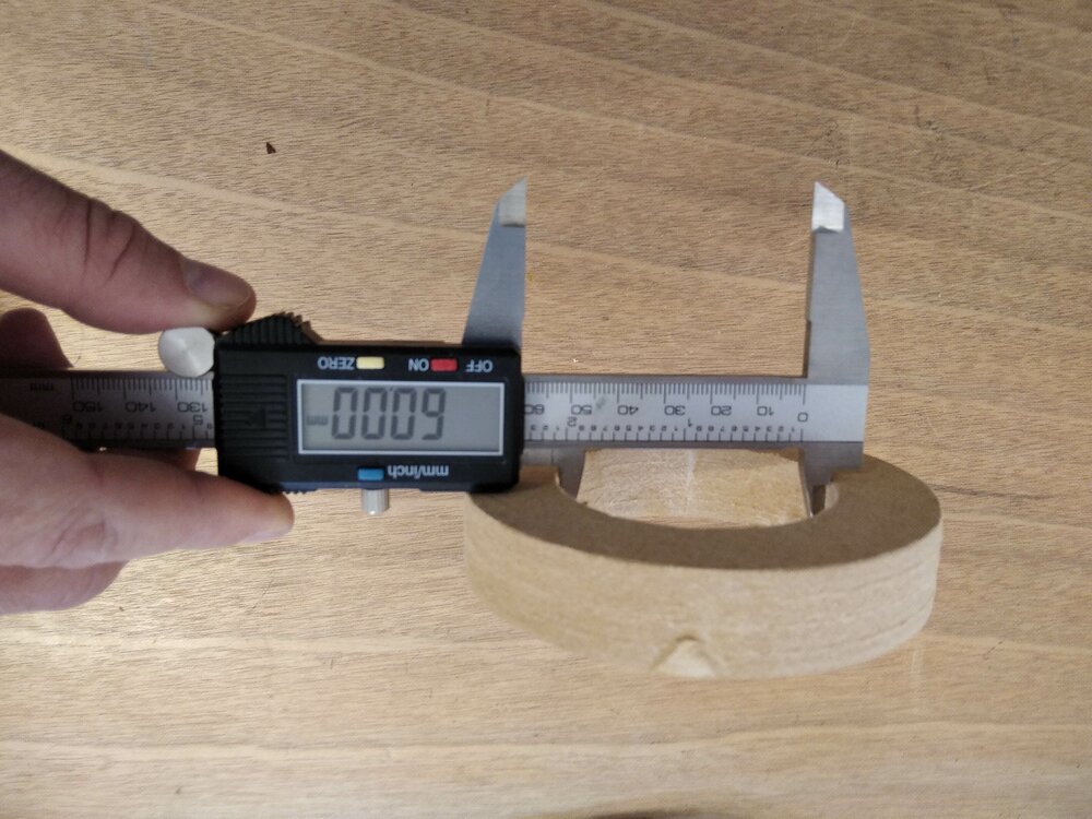
So here is the result.

It's perfectly square =).

The outer circle is exactly at like I set on CamBam.

And the same for the inner circle. So there is no runout on the CNC.
Finger joints tolerance
As I want to create some finger joints this week, I would love to test the tolerance, for a nice fitting wood joint.
For that, I want to give a try to the Path Workbench of FreeCAD.
Design the joints
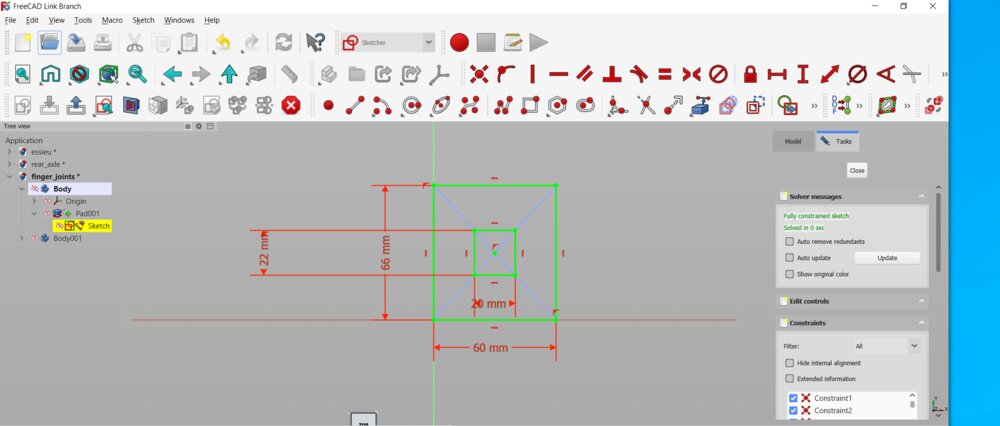
In FreeCAD I started a new sketch. The idea is just to test a fitting joint. So I first need a square with a square hole.
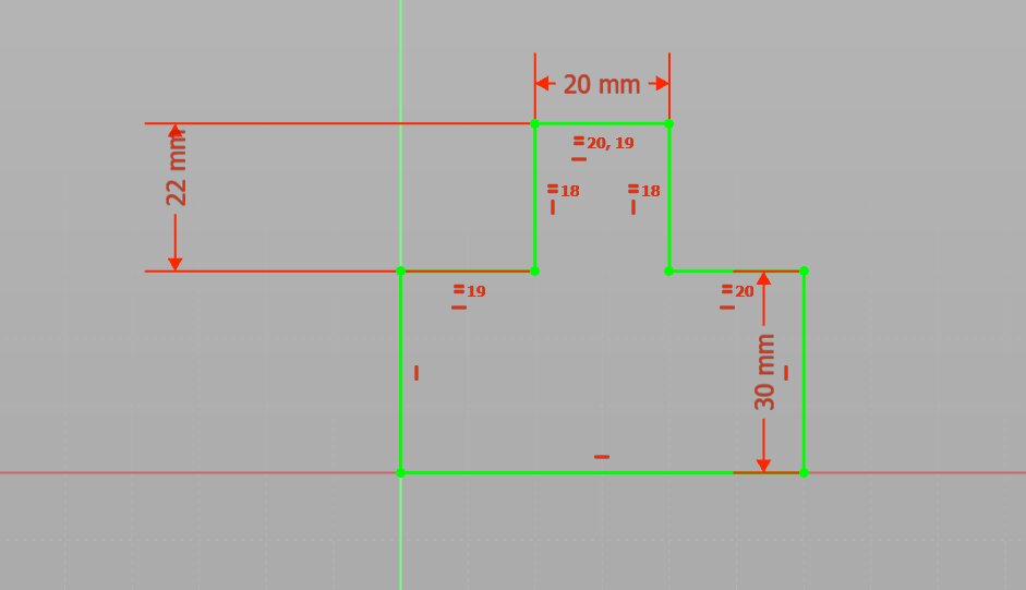
Then a tab to fit into.
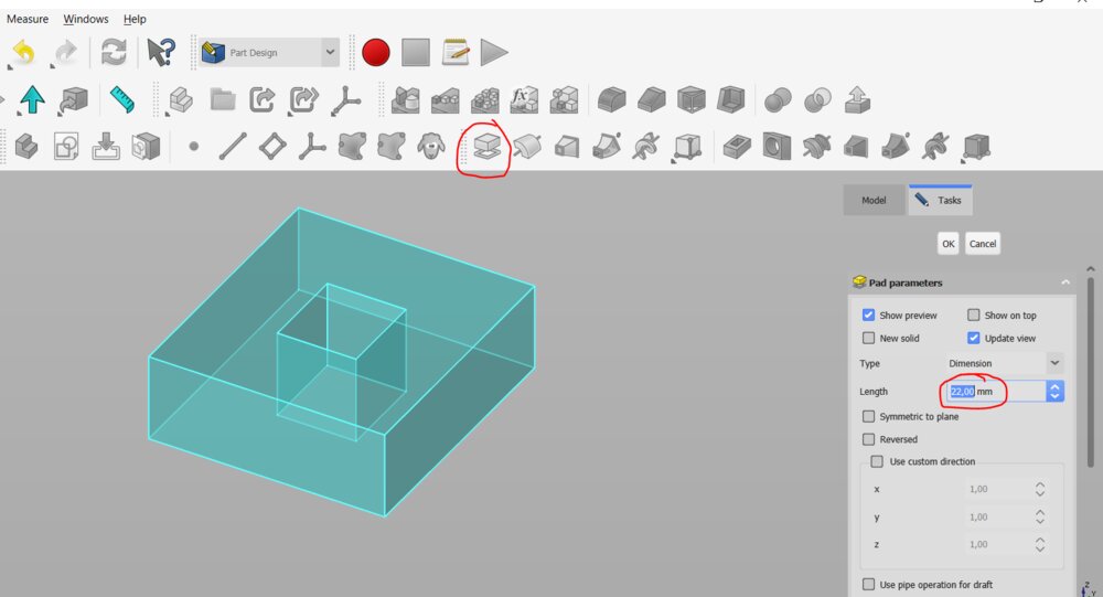
I then create a pad from the sketches (like in week 2, a month ago already, time flies !).
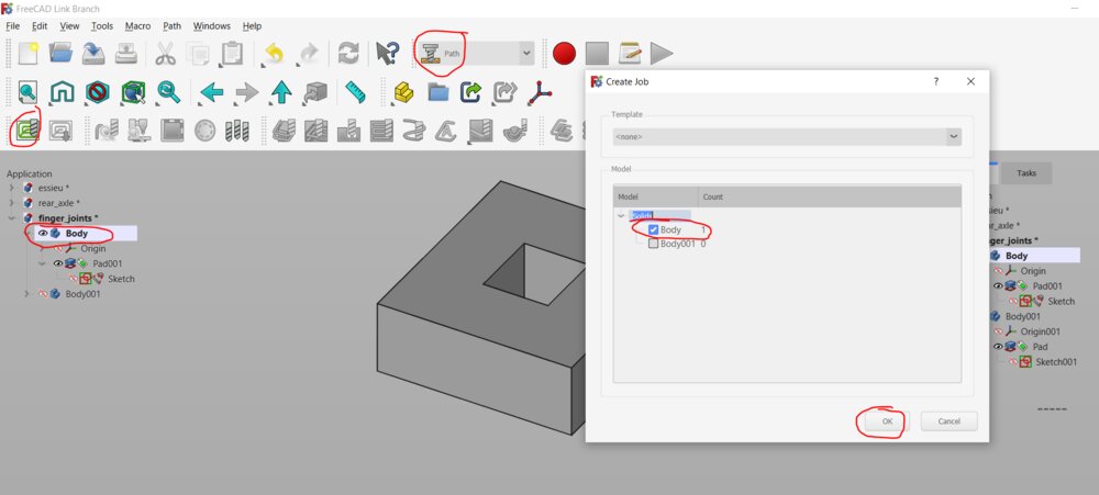
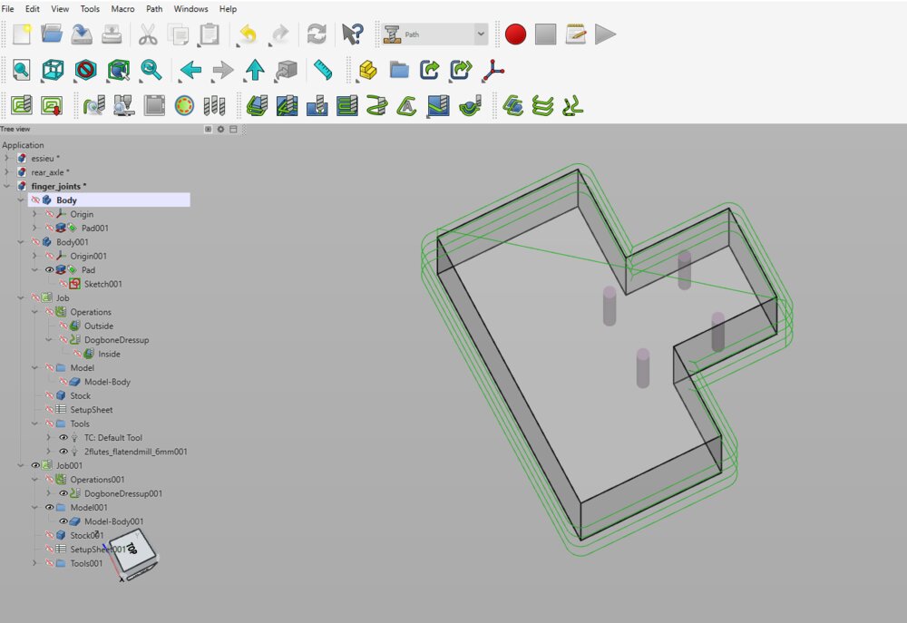
Then in the Path Workbench I created a new Job and selected the first body to start with.
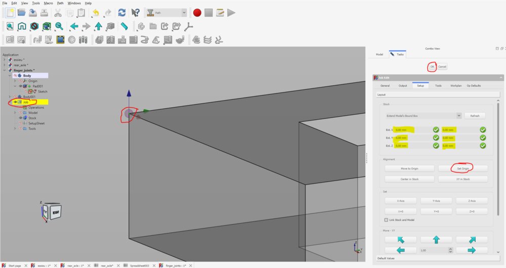
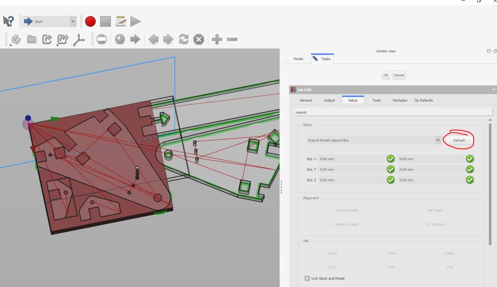
I set the stock as the model and select the point where I want my origin to be.
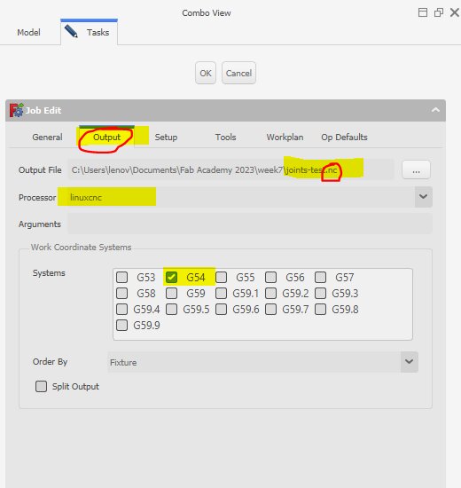
There, I also chose a name for my G-code output. By experience, I know that the linuxcnc Post-processor is doing a great job. But I should look for maybe a better processor for the Richauto A11 controller that's piloting the CNC.
It's in that panel, that I chose the .nc extencsion for my toolpath file, as it's what my CNC Router need.
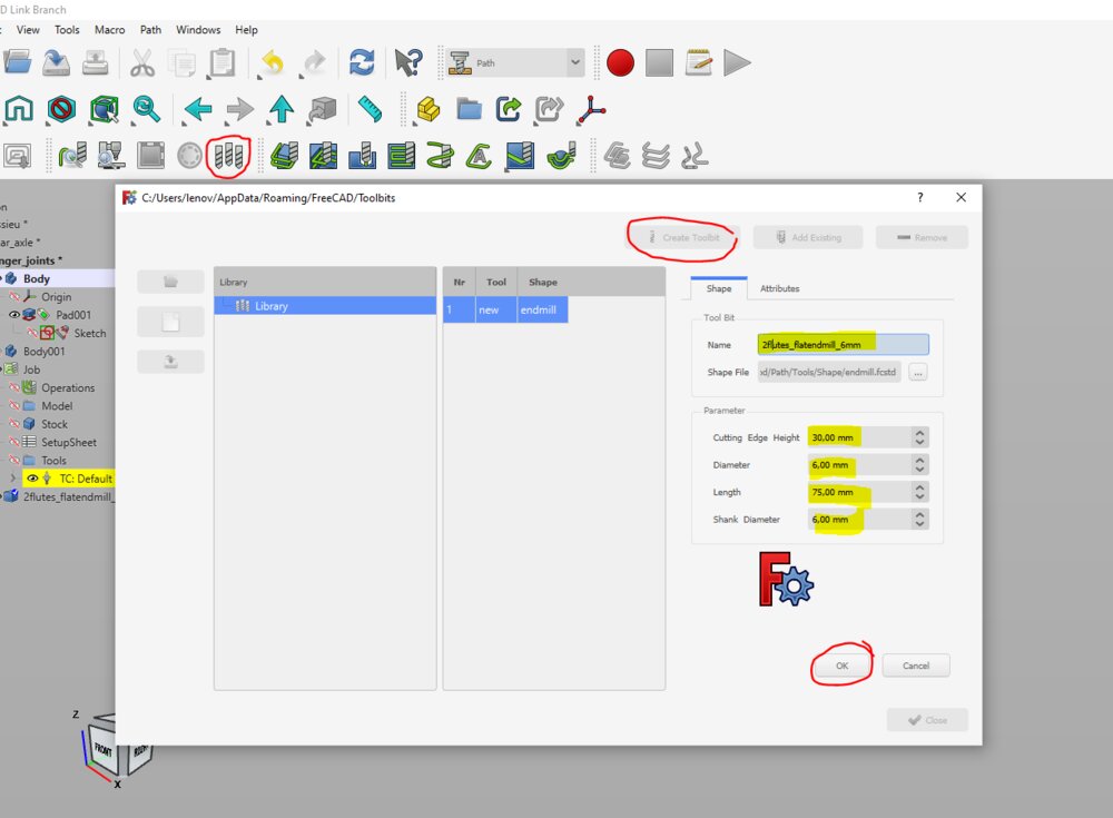
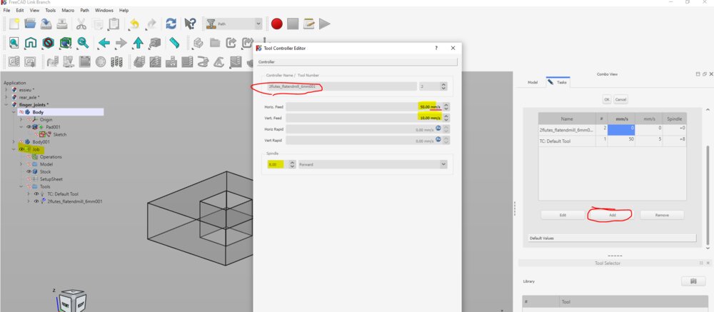
A need also to create a tool bits that I'll use to machine the assignments of the week. I can then add it to the job and chose the cutting feedrate.
By default, the unit of the speed is set to and not as we saw earlier.
Now that I have a tool bit, it can be selected for the milling job.

Now I can create an operation called "profile" that will cut the "contour" of the piece of wood.
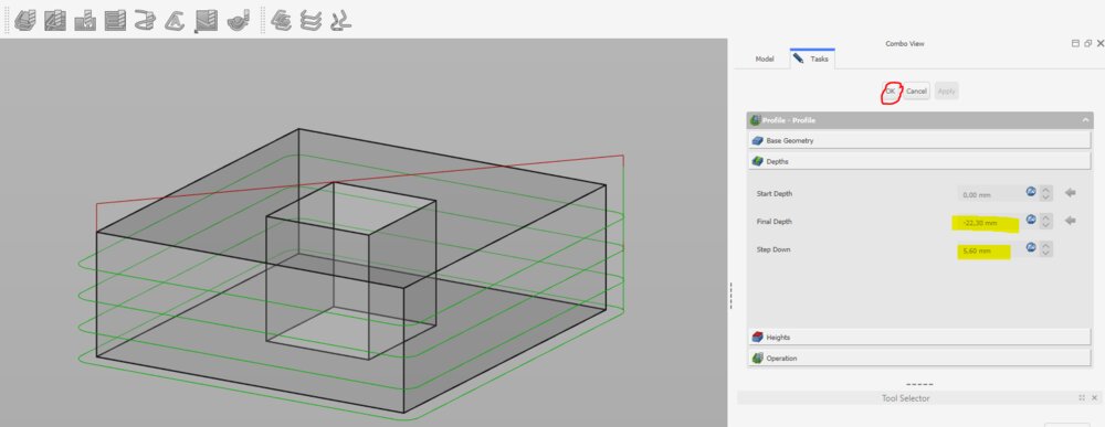
I defined the final Depth and the step down of the toolpath.
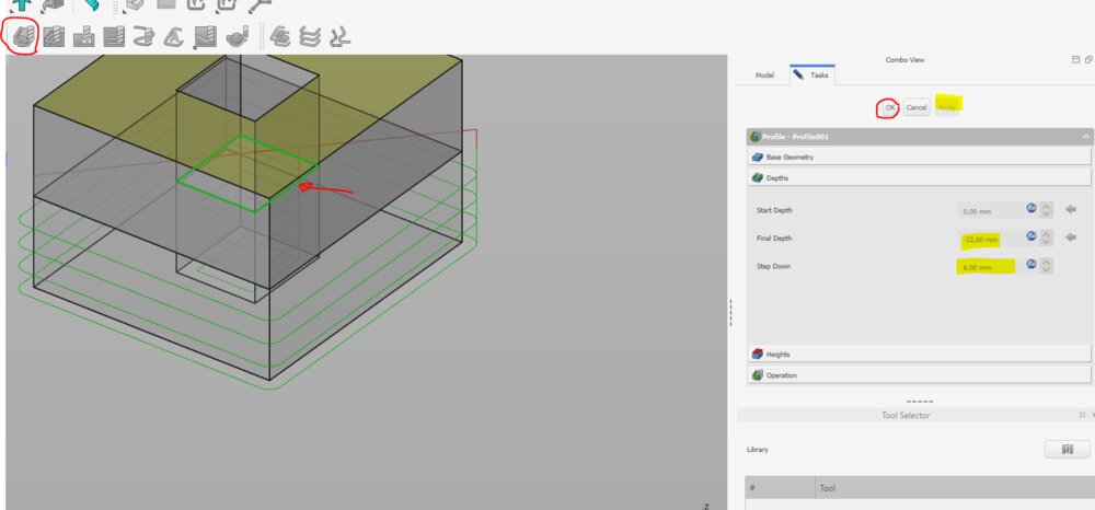
I did it also for the inner rectangle.

The rectangle inside of the piece, I need to do some dogbones if I want my joint to fit together. For that, I used the Dressup function of FreeCAD.
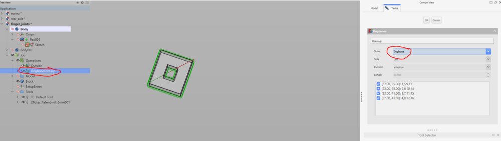
There are different style, I chose the default one called "dogbone".
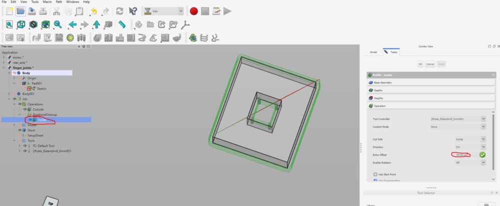
I create an extra joint tolerance for the hole cut of following this answer. For that is the profile toolpath (contour) we can add an Extra Offset
Then I did exactly the same for the other piece.
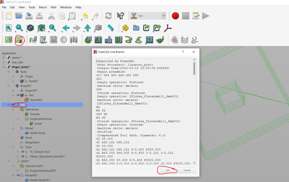
I can now post-process the toolpath to generate the Gcode.

Actually, I forget to create some tabs to hold the piece to the main board. So I use another Dressup called Tag Dress-up.

Now I can look at the final result by simulating the job. It's good for my, so let's send the G-code to the CNC.

Here the result on the OSB.
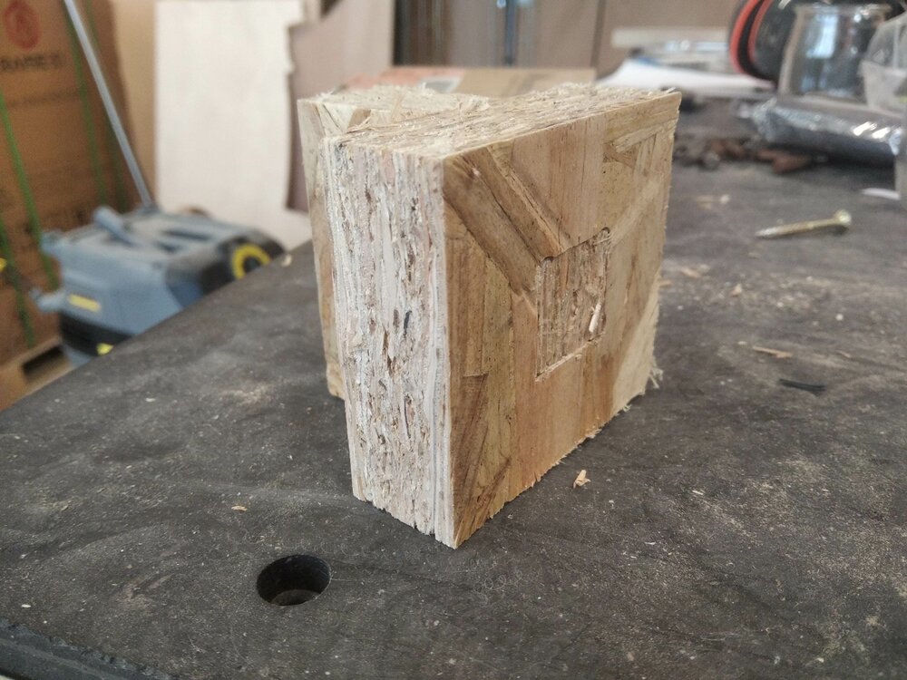
The joint fi perfectly, on the first try ! =D
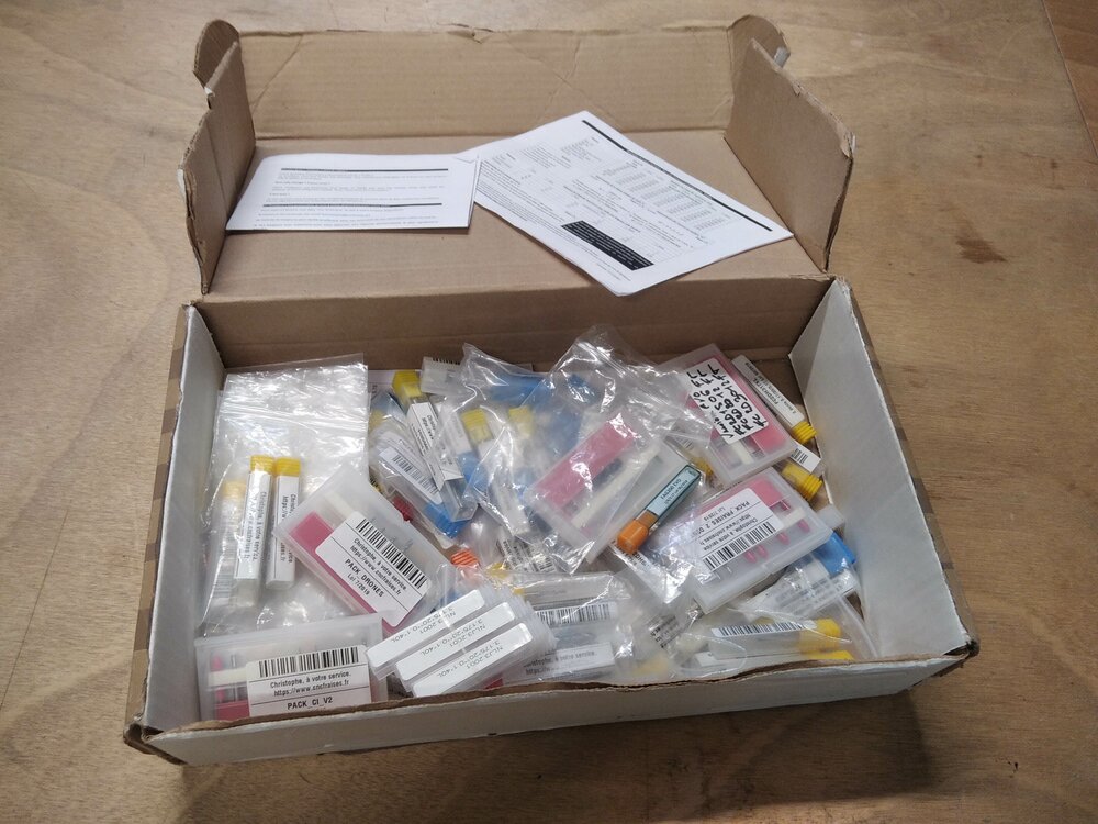
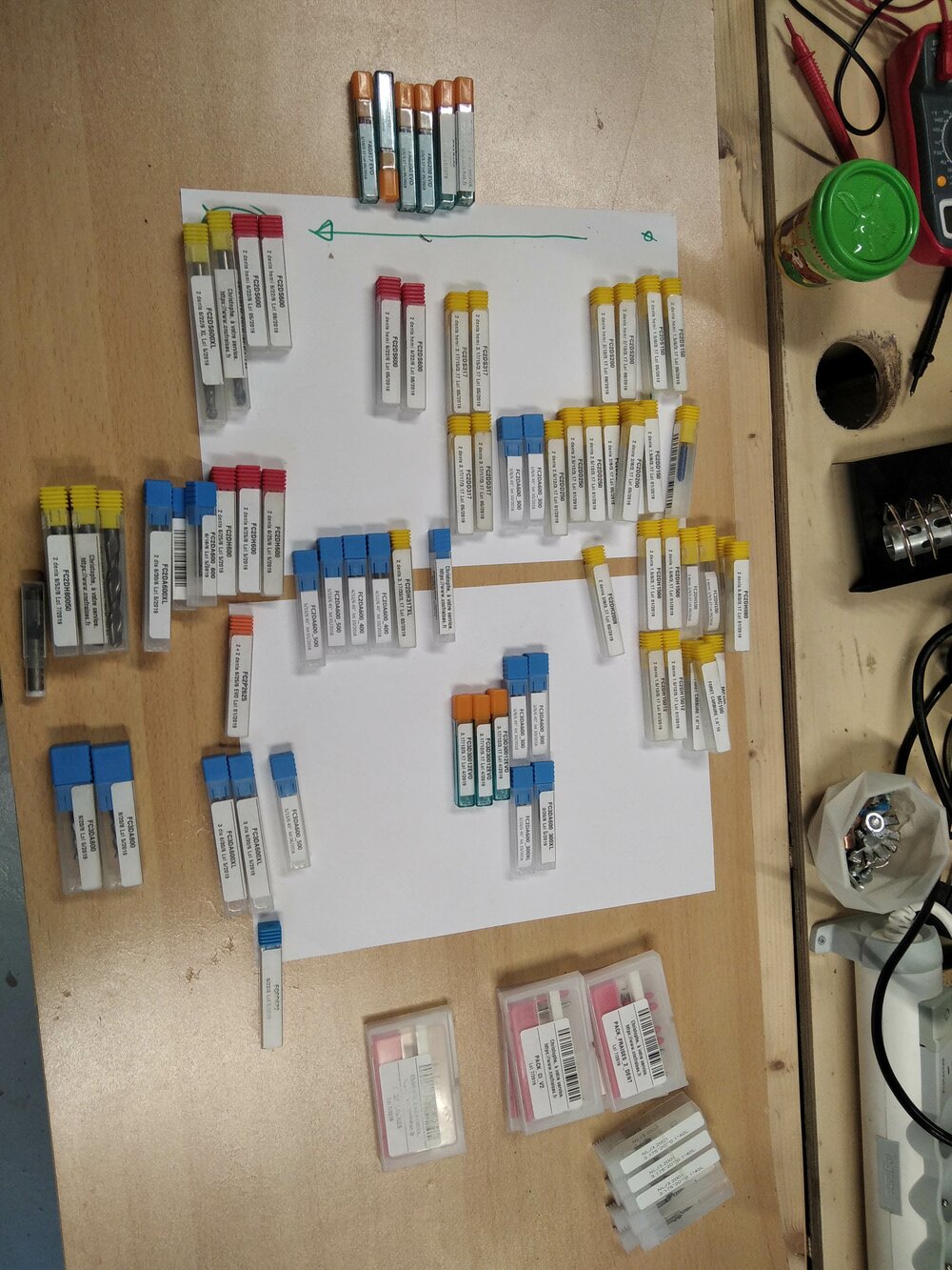
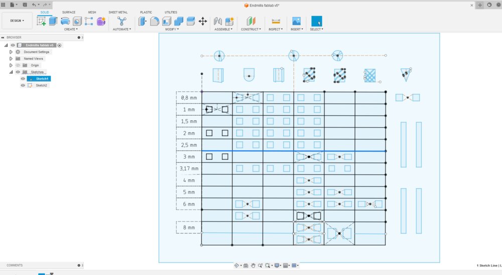
Order all the end-milling tools
I wanted to try the CAM on Fusion 360 with a board to store the Endmills of the fablab (it's a mess), but I didn't have enough time. So maybe later...
TODO: Machining the bits storage and write comments
Note: look like there is a post-processor for our Richauto A11 CNC Controller for Fusion360 https://cam.autodesk.com/hsmposts?p=richauto I need to try it. Update The post-processor works perfectly.
Building a part of the Final project
So the idea for the week is to see if I can rebuild a trike prototype I have in my garage from numerical command machines.

I'll start small, with the rear of the trike that holds the wheels.
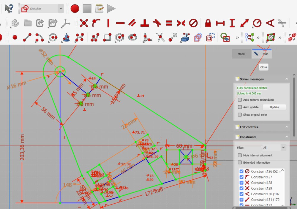
So first I resketch the rear wheel support. Changing it a bit because I want to have fingers joints to fix the joint-ball axe and a T-Bolt joint to fix the axle link between the two wheel supports/holders.
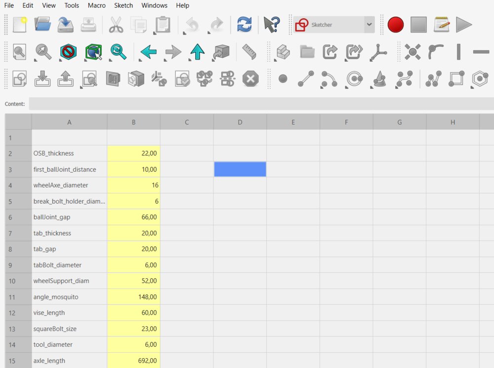
I added some parameters, like the OSB_thickness or the tab_gap. And then create the pad from the sketch.
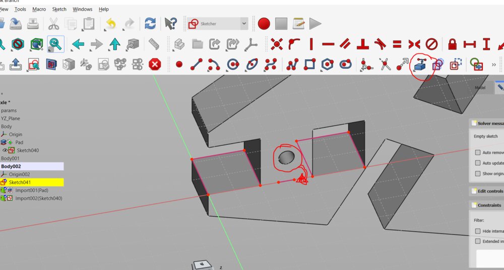
Then I worked on the link between the two rear wheel support. So I created a new sketch and import some lines from the other sketch. Like the circle for the T-Bolt joint.

I only draw the left side of it as I will mirror it.
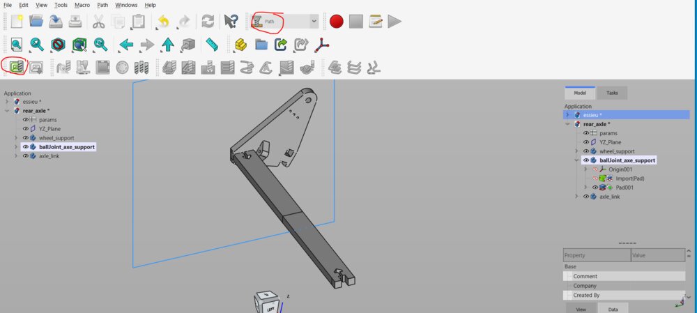
When the pad and the mirror is done. Then I can switch to the Path Workbench. So, as I did before, I create some new jobs.
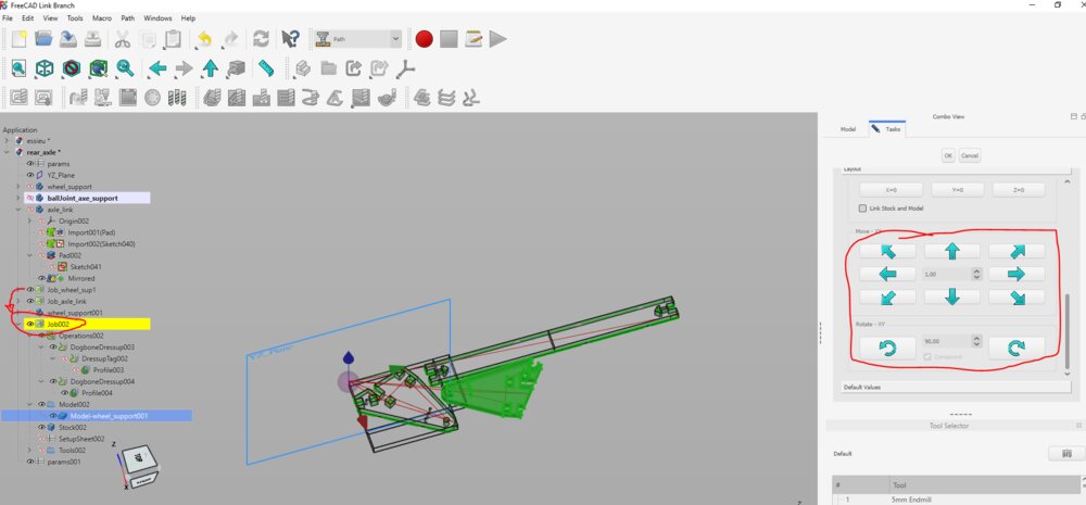
The most difficult part here was to arrange the pieces in one plan. So I played with the origin of the jobs, to rotate and move the toolpaths as they were on the same plane.

For the *Ballpoint axle support", as they are not 90° from none of the XYZ Axis, I had to redefine the Z axis by selecting one Edge of the body.
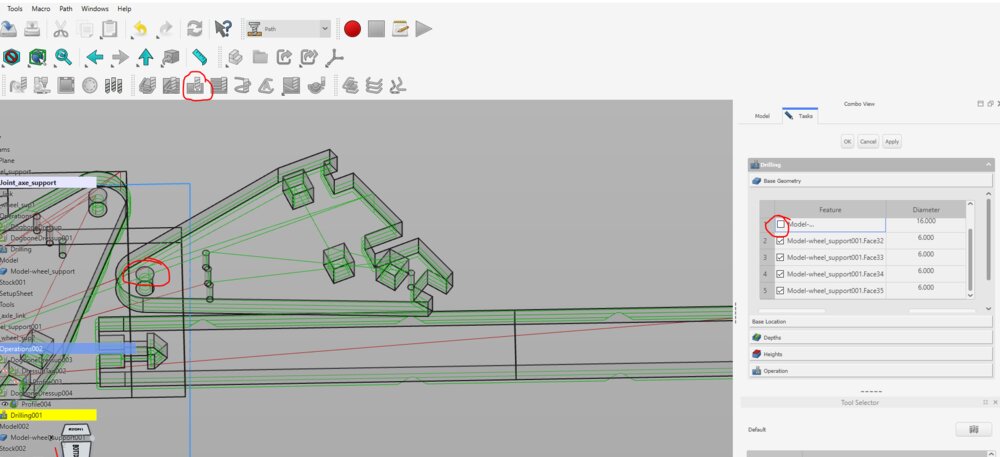
I also added a Drill operation for the holes on the board.
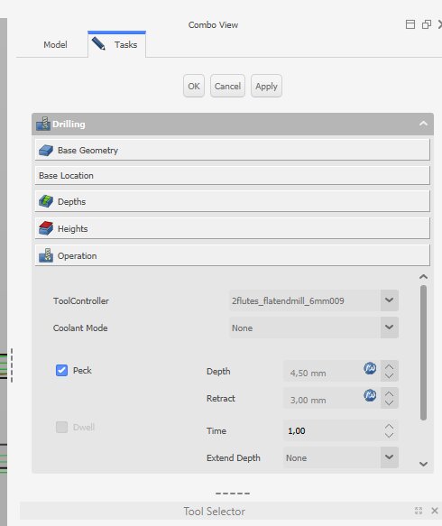
And activate the Peck function to remove wood ships.
I could then simulate the job.
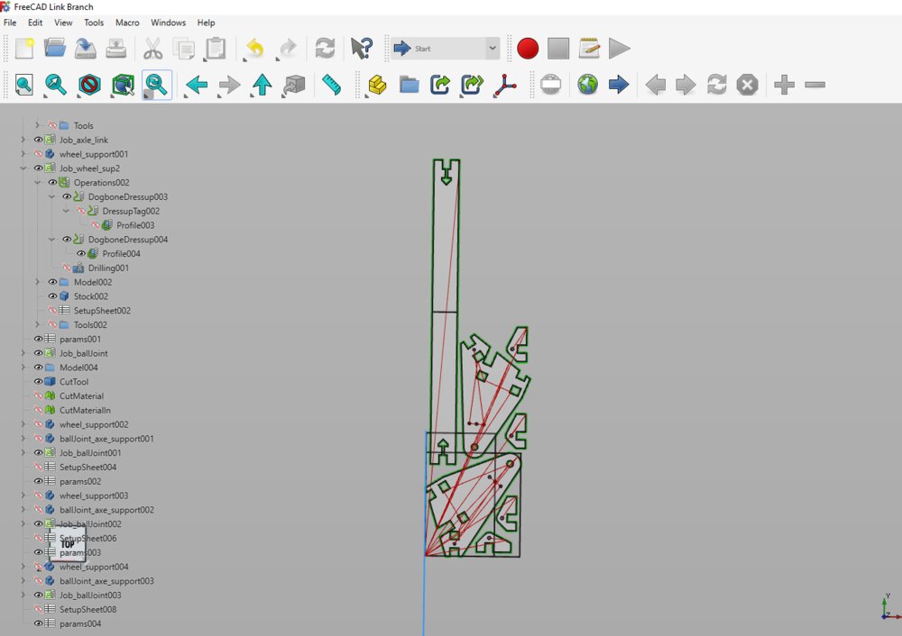
Here we go, after some hours all the toolpath are aligned on one plane. To be honest, it's much quicker with a 2D drawing on CamBam... I need to watch more FreeCAD tutorials because this process is super slow...
Let's machine it!
At the end of the video, we can see the function peck chosen in the drill toolpath.

I forget to put some tabs in one of the pieces. So it damaged the square. I had to re-cut one more piece of the ball-joint axe holder.
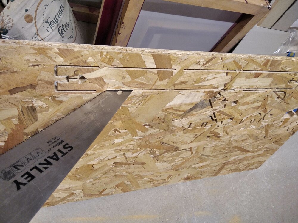
I use a saw to remove some tabs as it is super quick.
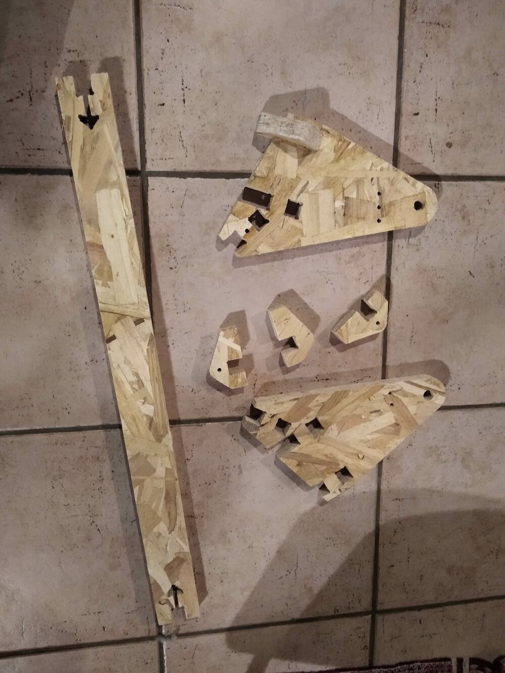
Here are all the pieces.
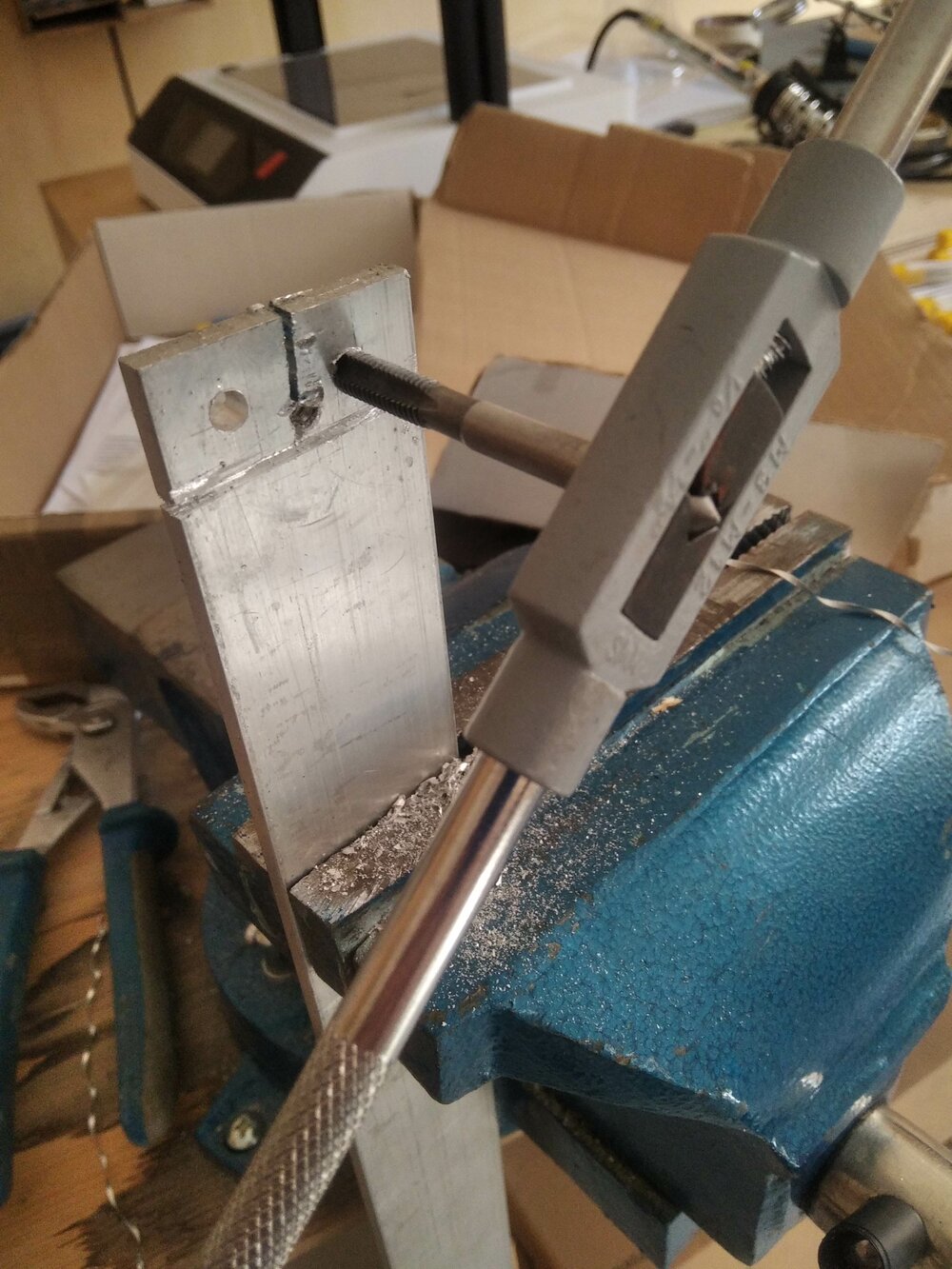
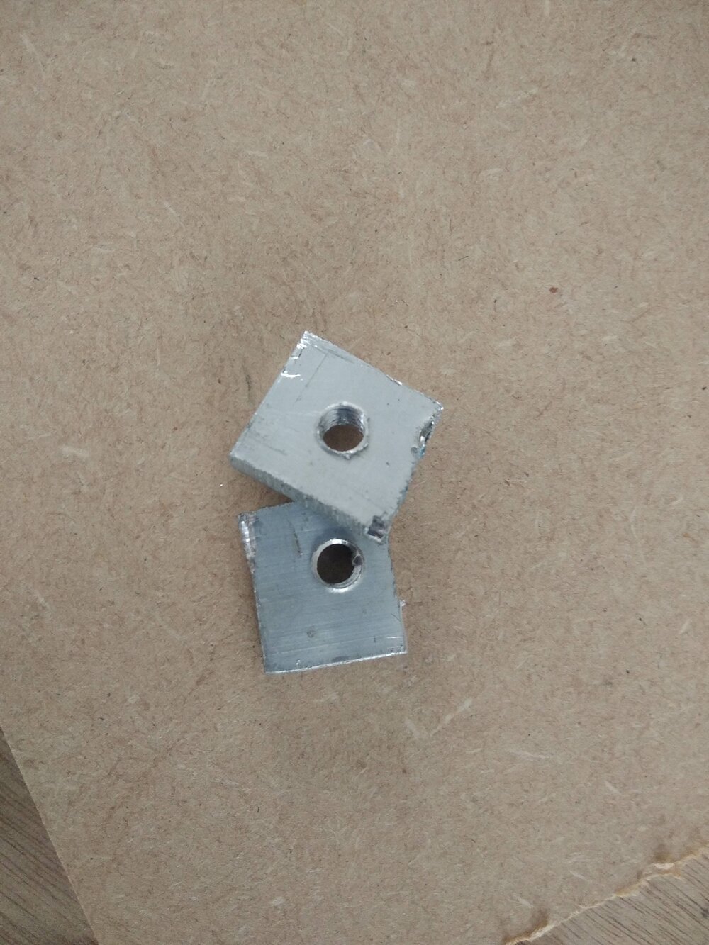
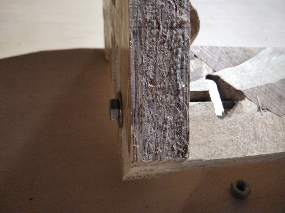
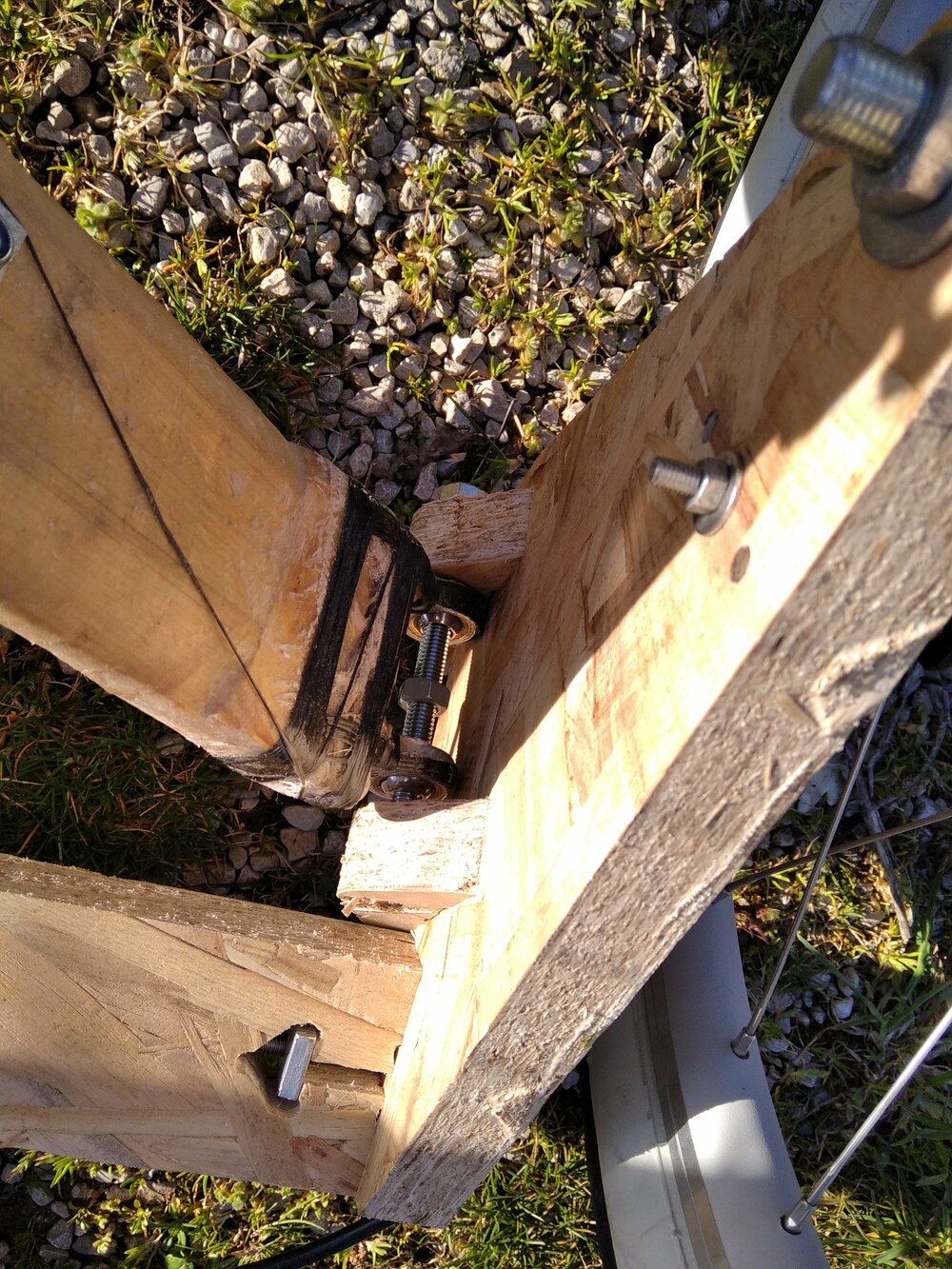
As I don't have a square bold for the T-Bolt joint, I decide to make a quickly and dirty one (I promise, next time I'll make it with the CNC =).
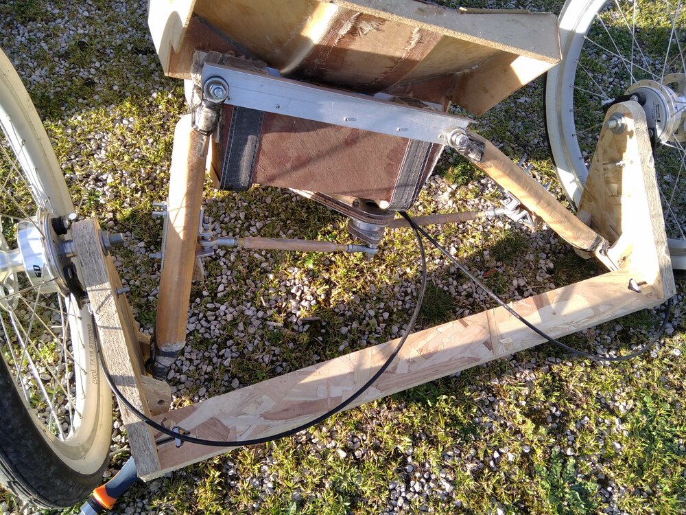
And now it's assembled!


And now on the trike!


Files
Here are the files for the week.