9: input devices
Individual Assignment
The individual assignment for this week is to measure something: add a sensor to a microcontroller board that I have designed and read it.
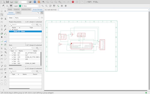
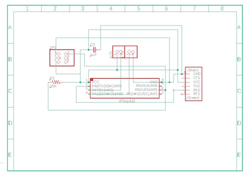
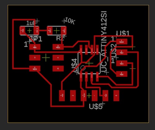
The first thing I did was create a new schematic copying the components of the board I designed in electronics design week (week 6). I kept most of the components: the ATtiny412 microcontroller chip, resistor, capacitor, and 6x1 pin header. I deleted the LED, button, and 2x1 header and replaced them with a 3x2 pin header and two 2x1 pin headers (I needed a 4x1 but I could not find one in my library). The input I chose for this week was an ultrasonic sensor. I based new my board design on Neil’s board. Here are what my edited schematic and new board files looked like:
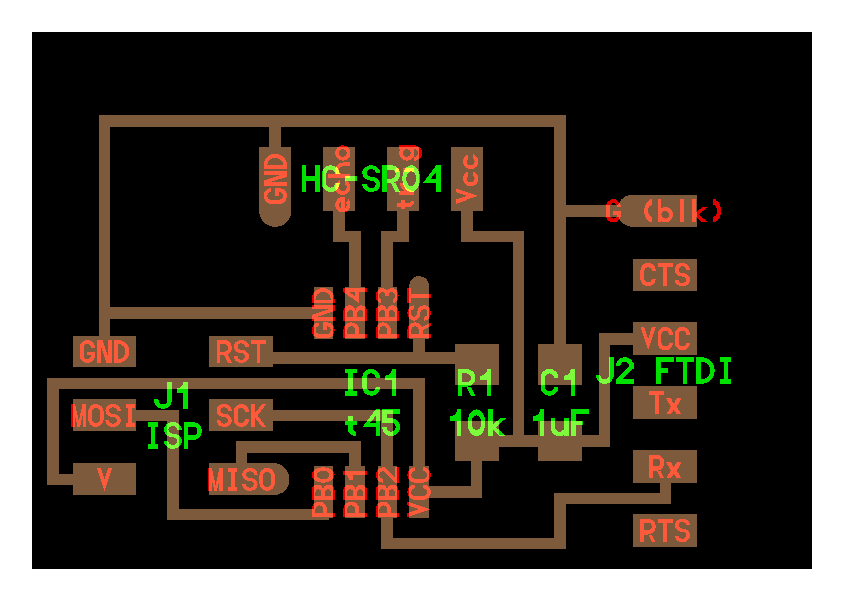
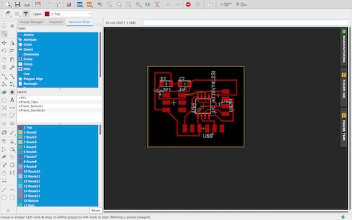
Because of COVID-19, my peers and I were unable to mill out our boards ourselves and instead put our files into a shared Google Drive folder so our instructors could mill them home. We then picked up the boards or they were dropped off at our houses so we could continue the assignment. Here is what my milled board looked like:
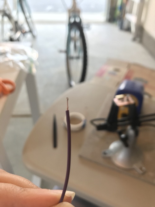
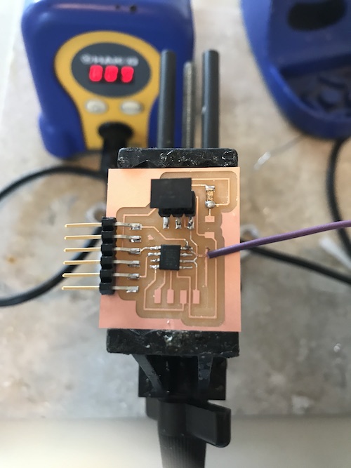
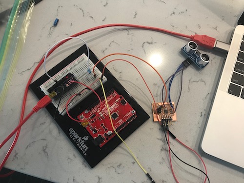
The next step was to solder all my components. After soldering everything but my sonar sensor, I realized that I had switched the pads for the sensor on my board, and had accidentally connected two pins to VCC instead of one to VCC and one to GND. Because of the situation, I decided to improvise and cut some female-to-female wires to solder directly to my board. I stripped the wire and added some solder on the tip of the wire so it would be easier to solder to the board.
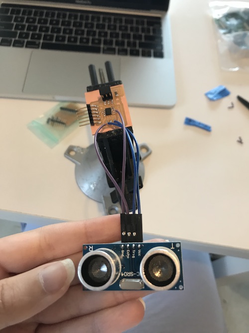
I then soldered one wire to my GND pin on the microcontroller, and the other three wires to the VCC and two pin connections on the board.
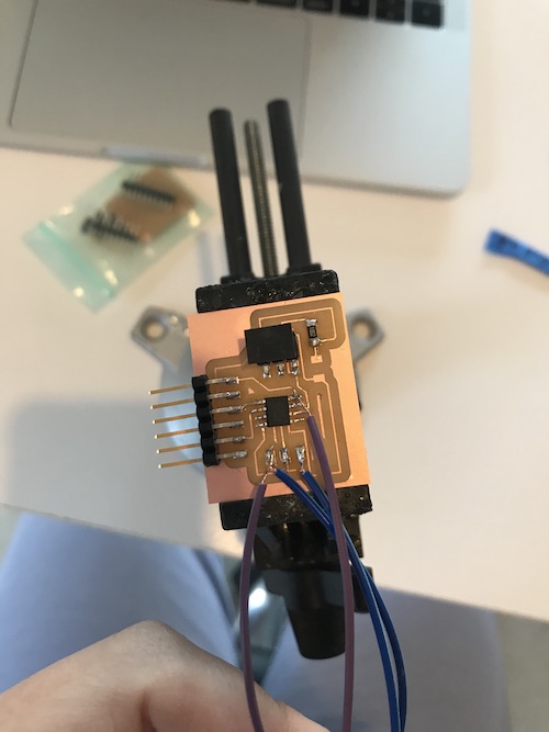
It looked kinda wack, but if it worked, it worked!
Afterwards, I went back and changed my schematic and board files appropriately.
For the software portion, I found a basic sonar sensor code here. The website also discussed how a sonar sensor worked and dissected the code it provided. In summary, a sonar sensor uses the trigger pin to send out a signal, which then finds an object, bounces off of that object, and is reflected back to the echo pin. This allows the sensor to calculate the distance of the object. I changed the trigger and echo pins in the code to match how the sonar sensor was on my board, making int trigPin = 2; and int echoPin = 1;. I was also advised to change the Serial.begin from 9600 to 115200, because of the ATtiny 412 microcontroller. Here is the final code:
/*
 * created by Rui Santos, https://randomnerdtutorials.com
 *
 * Complete Guide for Ultrasonic Sensor HC-SR04
 *
    Ultrasonic sensor Pins:
        VCC: +5VDC
        Trig : Trigger (INPUT) - Pin 2
        Echo: Echo (OUTPUT) - Pin 1
        GND: GND
 */

int trigPin = 2;    // Trigger
int echoPin = 1;    // Echo
long duration, cm, inches;

void setup() {
  //Serial Port begin
  Serial.begin (115200);
  //Define inputs and outputs
  pinMode(trigPin, OUTPUT);
  pinMode(echoPin, INPUT);
}

void loop() {
  // The sensor is triggered by a HIGH pulse of 10 or more microseconds.
  // Give a short LOW pulse beforehand to ensure a clean HIGH pulse:
  digitalWrite(trigPin, LOW);
  delayMicroseconds(5);
  digitalWrite(trigPin, HIGH);
  delayMicroseconds(10);
  digitalWrite(trigPin, LOW);

  // Read the signal from the sensor: a HIGH pulse whose
  // duration is the time (in microseconds) from the sending
  // of the ping to the reception of its echo off of an object.
  pinMode(echoPin, INPUT);
  duration = pulseIn(echoPin, HIGH);

  // Convert the time into a distance
  cm = (duration/2) / 29.1;     // Divide by 29.1 or multiply by 0.0343
  inches = (duration/2) / 74;   // Divide by 74 or multiply by 0.0135

  Serial.print(inches);
  Serial.print("in, ");
  Serial.print(cm);
  Serial.print("cm");
  Serial.println();

  delay(250);
}
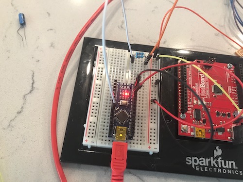
Because I was having some issues with the Sparkfun Redboard I was using previously to code my board, my instructor Mr. Rudolph gave me an Arduino Nano to turn into a jtag2updi programmer. Again, I followed this Github tutorial to do this. I compiled and uploaded the jtag2updi.ino sketch that was in the folder I previously downloaded to the Nano. I then added the necessary hardware (a 22uF capacitor at RST and GND and some wires to hook up my board) to get ready to program my board. I already had a resistor on my board, so I did not add a 4.7k through-hole resistor to the breadboard. Here is what my setup looked like:
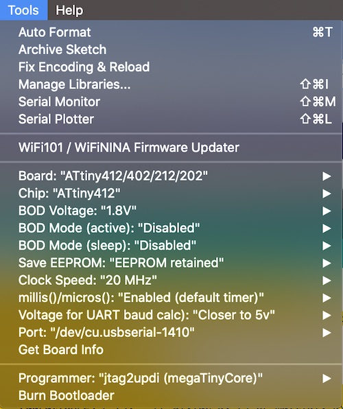
On Arduino, I changed the settings to this:
When I tried to upload my code (using Upload Using Programmer), I was given this error message:

Basically, it said that my serial port did not exist or my board was not connected. Because the code compiled fine, I figured this was a hardware issue. I checked all my connections with a multimeter and tried to upload it again, but was still prompted with the same error. I restarted Arduino and my laptop but it still did not work. I then connected the Sparkfun Redboard to see if anything would upload. I ran a simple Blink code, which went through, confusing me. I went back to my original code and tried different Baud rates, as suggested in the Troubleshooting section here. Doing this only gave me the continuous error avrdude: jtagmkII_getsync(): sign-on command: status -1. I tried Googling the error, but didn’t have much luck finding a solution.
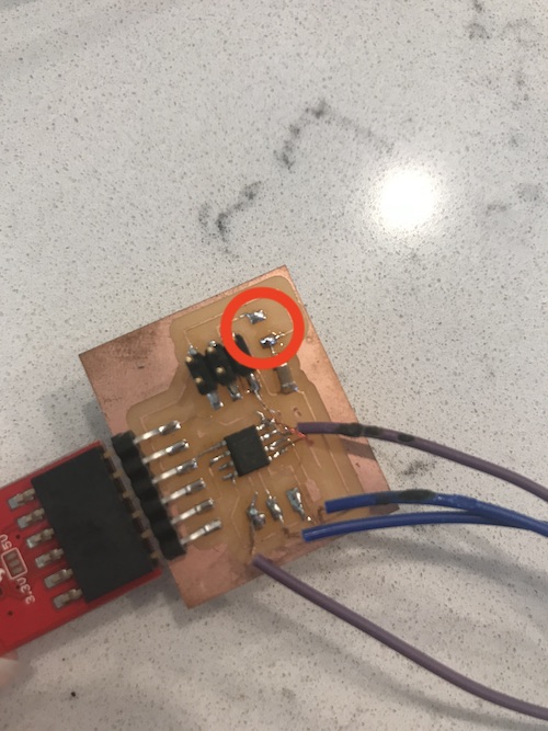
After meeting with one of my instructors, Mr. Rudolph, he found that on my board, I had connected a resistor to the UPDI pin. This was most likely causing issues in the signal. He advised me to either remove the resistor or rewire the UPDI pin on the microcontroller to a different pin header. Another mistake I was doing was uploading my code using Upload Using Programmer instead of just Upload. I removed the resistor and made sure all my settings were correct. Here you can see where I removed the resistor:
Here was my final setup:
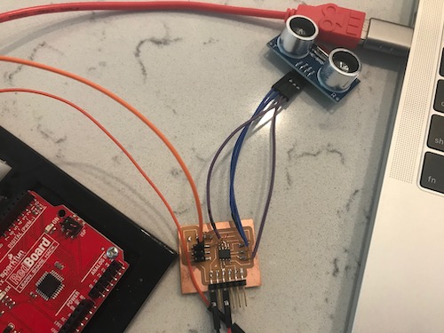
Here you can see the sonar sensor working from the serial monitor!
To download my files for this week, click here.
Group Assignment
The group assignment this week was to probe an input device’s analog levels and digital signals. You can view the whole process on our group page here.