7: computer controlled machining
Make Something Big
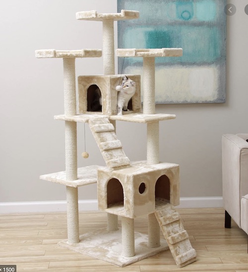
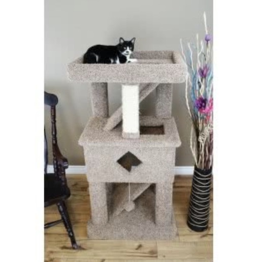
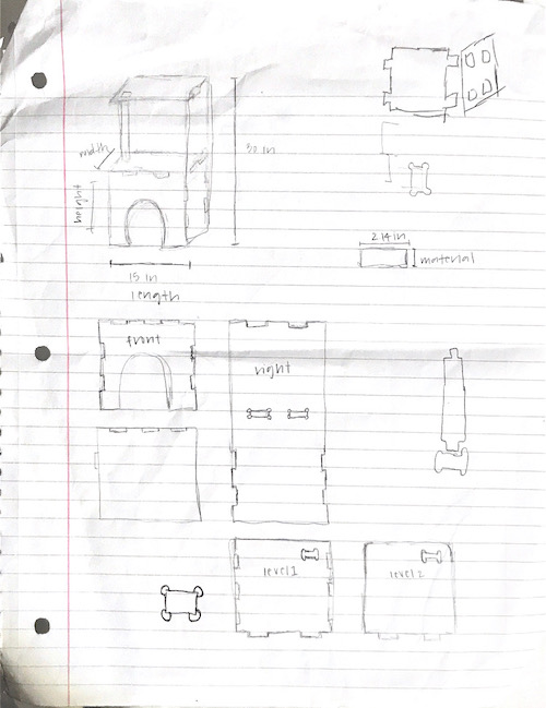
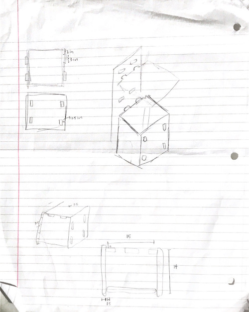
The individual assignment for this week was to make (design+mill+assemble) something big. This assignment was very broad and allowed for a lot of creativity. After surveying my room for any furniture I might need, I realized I could use this week to build something not for myself, but for my cat, Daisy. I searched the web for small cat jungle gyms and after getting some ideas, sketched my design. Here was some of my inspiration and my sketch:
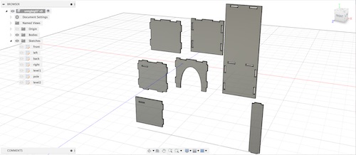
I decided to design the structure in Fusion360, using parameters and different sketches for each part so I could stay organized. I named each sketch and body by what part it was:
front
left
right
back
level1
level2
pole
Key tools I used for this design was the Mirror tool, Rectangular Pattern tool, and construction lines.
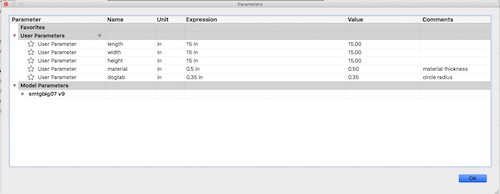
I made a couple user parameters so I would be able to change my design if I needed to later.
I incorporated dog-bone tabs and slot-fit tabs into my design. Though I manually combined a rectangle and circles for my dog-bone tabs, I later realized there was a way to do it on both Fusion and Aspire, so that was cool. On Aspire, you can use the ‘Fillet Tool’ to make both dog-bone and t-bone tabs.
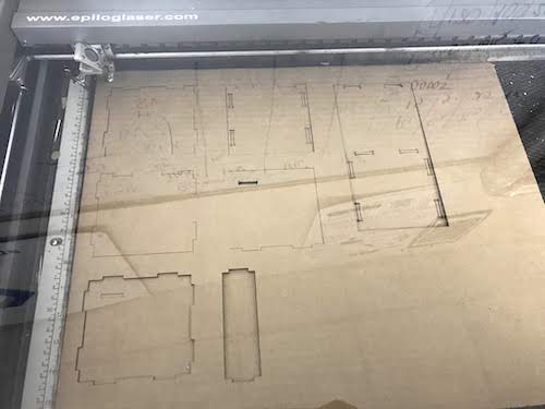
Once I finished my sketching my design, I extruded them into bodies and downloaded the sketches as a DXF file to put into Corel so I could laser cut a small prototype.
I scaled my design down to 26% in Corel so that the tabs would fit together with the 0.13in cardboard, as opposed to the 0.5in wood I planned to use on the Shopbot. Unfortunately, all my construction lines and all other lines showed up on the DXF, so I had to go through and delete them with the Segment Delete tool. Here are my lasercut pieces:
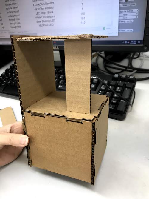
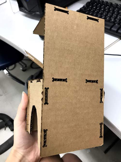
Upon putting it together, I realized that I had made two errors. One, the pole was too long (15in instead of 14) and the slot for the pole on the ‘level2’ piece was rotated the wrong way.
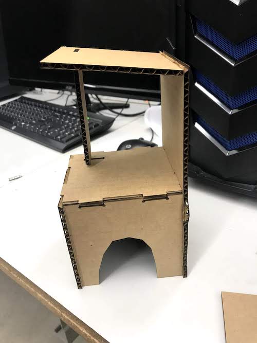
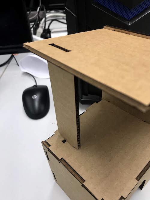
I fixed these two pieces and recut them. Other than that, the structure fit together well and looked adequate.
Upon discussing with my instructors, I decided to increase the height of my overall design so it would really satisfy the “make something big” assignment. My final design was 15in x 15in x 40in.
Next, I had to generate the toolpaths for my design, which I did using Aspire. I exported my edited Corel file as a DXF so the construction lines would not show up again. Upon opening the software, I selected ‘Open Existing File’, set the width to 48in and the height to 96in, the thickness to 0.5in, the Z Zero Position as the machine bed, the XY Datum Position as the bottom left corner, and clicked Okay. I then selected my pieces and positioned them onto the bed. To create the toolpaths, I selected of the shapes and clicked Profile Cut. I changed the number of passes to 3 in order to decrease the time the Shopbot would take to cut. I also added tabs to my shapes so they would stay in place while being cut, and I would chisel them out afterwards. I was going to use a 1/4” bit, so I selected this. I then clicked ‘Calculate Toolpaths’. I previewed the toolpaths to ensure the pieces would fully cut through and my tabs were visible. Finally, I clicked ‘Save Toolpaths’ and saved them as a ‘ShopBot (inch)(*.sbp)’.
Because some of my peers were using our lab’s large Shopbot, I decided to use the small one so I could go ahead and start cutting my pieces. Unfortunately, that meant I had to change the settings on my Aspire file and re-generate the toolpaths, but it was okay. I changed the dimensions to 36in x 24in. Because this was smaller, I could only cut several pieces at a time. I put the front, level2, and pole pieces on the file to cut first. Additionally, by recommendation of one of my instructors, I generated a separate toolpath for the dog-bone tab on the level2 piece and made the cut ‘inside’ instead of ‘outside’ for how the bit would cut it.
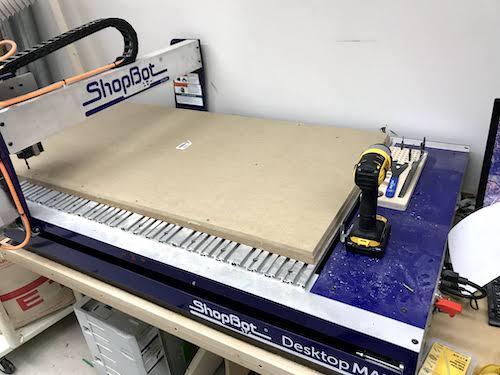
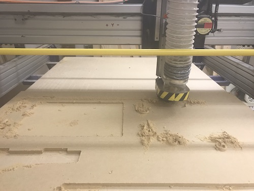
Before starting to cut my pieces, I had to set up everything on the small Shopbot. This included homing the axes and drilling down my material. I used 0.5in MDF because it was smooth and a bit lighter than wood.
I first used the bed and z-plate to home the z-axis. I then used the C3 command to home the X and Y axes using proximity switches.
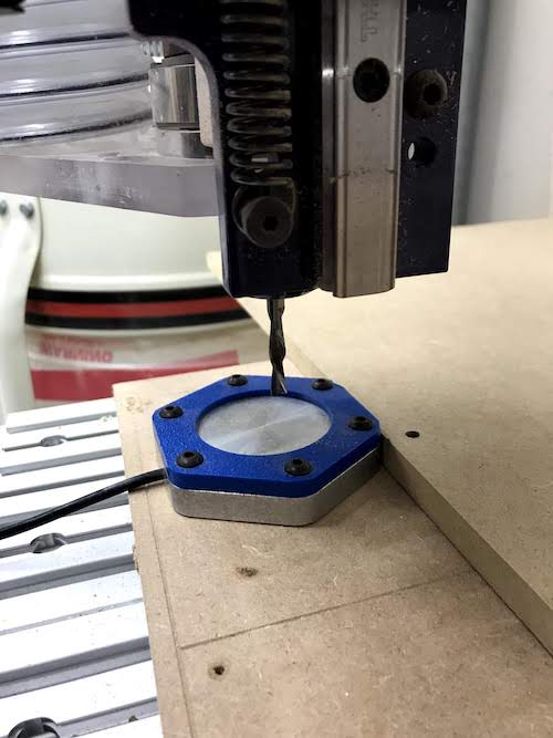
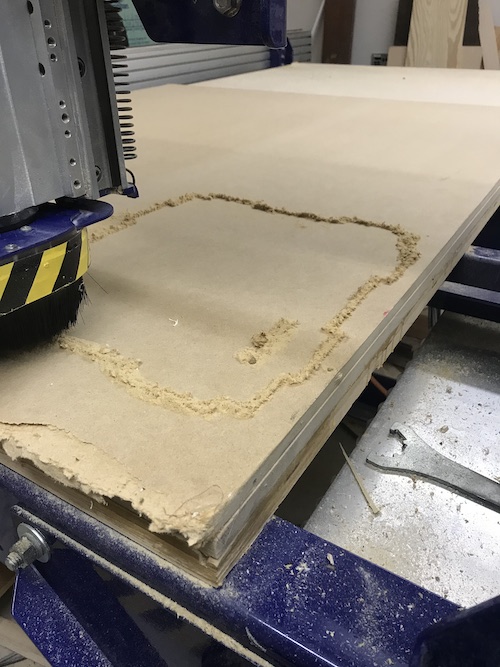
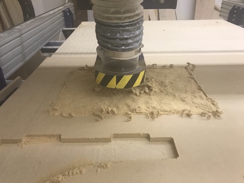
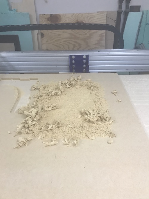
I then drilled the MDF at the corners into the bed. I had to make sure I drilled the material where the bit would not cut my design.
Here is the MDF on the Shopbot:
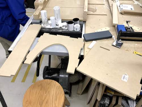
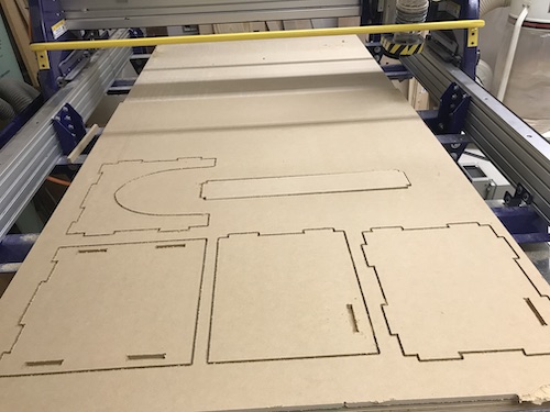
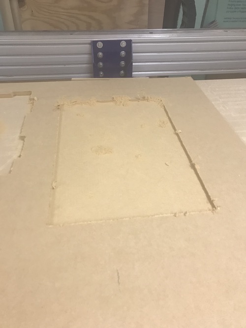
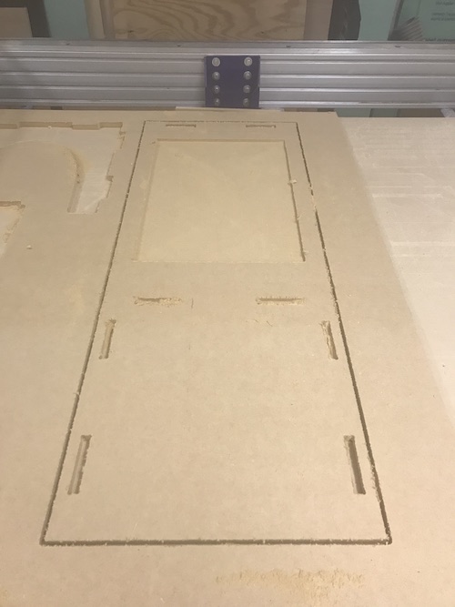
Here are my pieces after being cut:
Unfortunately, my lab closed due to COVID-19, so I was unable to finish this week’s assignment until a couple months later.
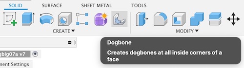
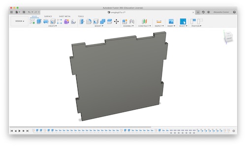
Once I got back into the lab, I had to recut my pieces. I could not find the 3 I had previously cut, and I needed to recut them anyway because I had forgotten to account for clearance whenever I was creating my Fusion360 file. I found that I had designed it very poorly the first time and did not use many parameters, so instead of going back through and fixing everything I decided to just redesign the structure. This actually did not take too long because I felt a lot more comfortable with Fusion at this point (this update comes after I’ve been working on my final project for about a week or two) and had my previous design as reference. The imperative part of redesigning was incorporating clearance. I decided to use MDF again, which I measured to be 0.51in thick. I decided to make the tabs 0.53, allowing for 0.02in of clearance. Another vital step was incorporating the dogbone tabs. Previously, I had done this manually by adding a circle to each edge of the rectangle. This was not only tedious but very inefficient. One of my peers, Elaine Liu showed me a Dogbone Add-in for Fusion. I downloaded the .zip file, installed it, and restarted Fusion. You can see that it showed up here:
I selected the bodies individually by selecting a face at a time. I made the tool diameter 0.25in because that was the size of the bit I would use.
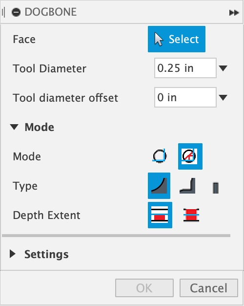
You can see that the dogbones were created!
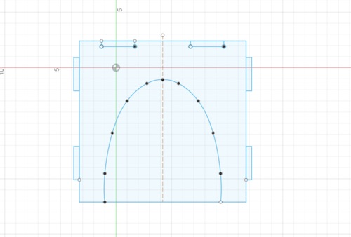
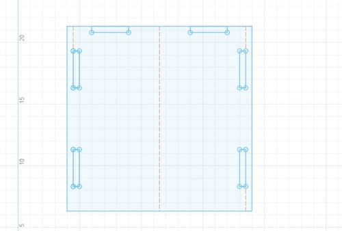
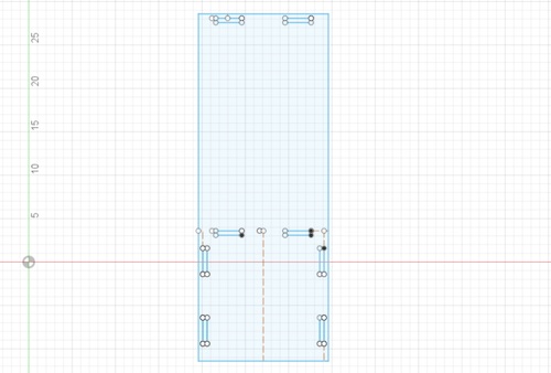
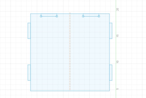
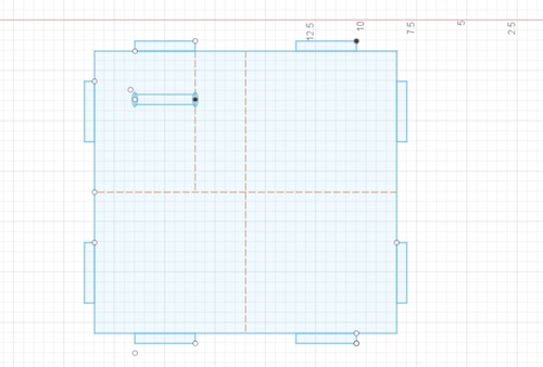
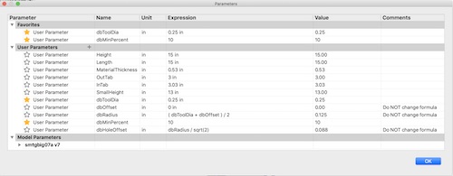
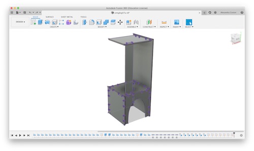
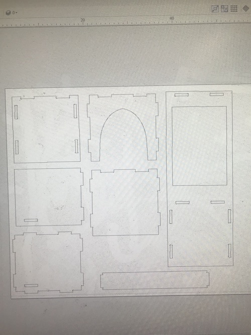
Because I was not going to recut a cardboard prototype, I decided to put my pieces together to see the final structure to make sure everything was right. To do this, I clicked Modify -> Align and aligned my shapes using the edges, rotating, and flipping them. Here are the parameters I used and my final design:
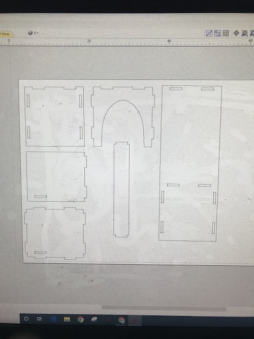
The next step was creating the toolpaths. My previous method as exporting it as a DXF was also inefficient because of the construction lines I used. I decided to try another method. I turned all my bodies into components, then clicked on each individual component and clicked Create Drawing. I created a new drawing for the first piece, then added the other pieces to that same drawing by clicking Drawing and selecting my sheet. I placed all of the pieces on one sheet, making sure the view of the pieces were right. I then clicked Output -> Output Sheet as DXF.
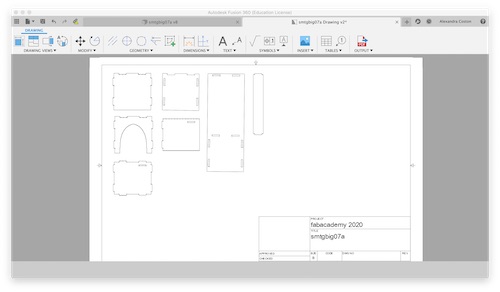
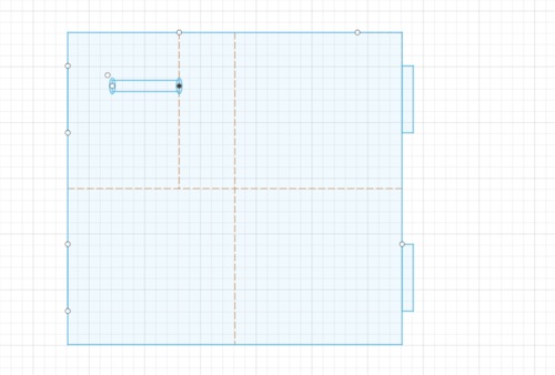
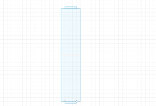
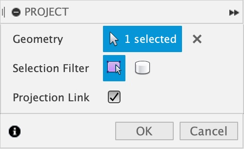
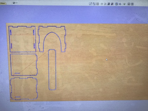
At the time, this seemed like a genius idea. It was only once I put the DXF file into Aspire and scaled it up that I realized that my plan was not so genius after all. For some reason there were multiple lines in places were there should not have been, not the mention the fact that there were numerous open vectors and when I tried to join them my design got all messed up. As I was inefficiently struggling to use the snip tool to delete the lines and join the vectors, Mr. Rudolph pointed out that there was a much better way to go about getting my file from Fusion to Aspire. One by one, I activated each component and created a new sketch on its face. I then clicked P to project the sketch. This did exactly what it sounds like, it used to body I selected to project it as a sketch. You can see that each component has the purple outline of the projection:
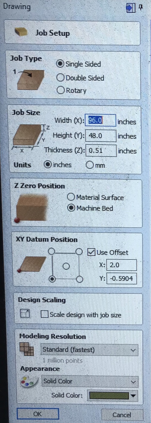
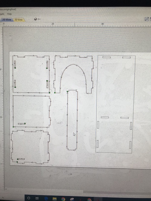
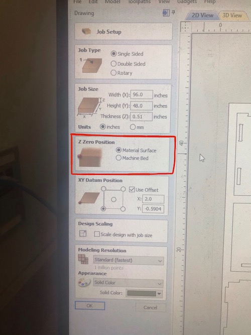
I then individually selected each projected sketch and clicked Save as DXF. I then downloaded each sketch and put them all on one Aspire file. I used our lab’s big Shopbot this time, so I made the X 96in and the Y 48in, and the thickness 0.51in. I made the Z Zero position the bed, but I would have to change it to the material surface for the pocket cut that I decided I would include. I decided to add a pocket cut because I could glue in some sisal material (the material that cats like to scratch). Here are the settings:
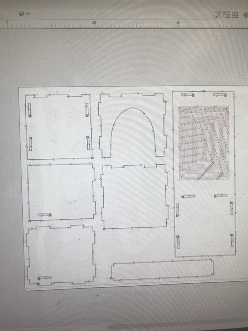
I positioned my pieces and created a profile cut for all the pieces but the long one that was the right piece.
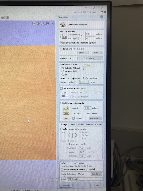
Here are the settings I used. I had it go all the way through the material (0.51in) in 4 passes. I added a couple tabs to each piece so that they would not move while being cut. My teacher, Mr. Dubick, created a workflow to instruct everyone on how to use the Shopbot. I followed these steps, saving my toolpaths and opening up the Shopbot software to get everything ready. I clicked File -> Part File Load to select my profile toolpath. I then clicked 1 3D Offset to run an aircut. Once I saw that everything was in the right place, I uploaded the file again and clicked 0 No Offset to run the actual cut.
Here is one of my pieces in the process of being cut and the 5 finished cut pieces:
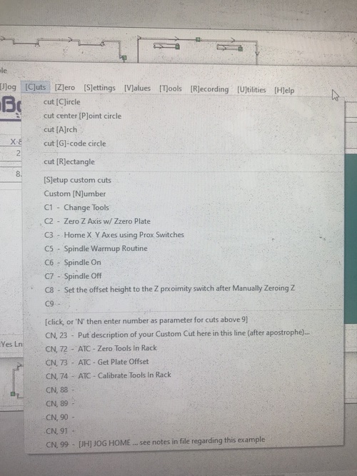
I cut the remaining pieces after the weekend, so I had to turn on the Shopbot, warm up the spindle, and re-home the axes. You can see that process in the group documentation, but basically I clicked C5 for the Spindle Warmup Routine and then C3 to Home X Y Axes using Prox. Switches. Because I was doing the pocket cut first, I also needed to re-zero the Z axis off of the material, which I did using C2 to Zero Z Axis w/ Zzero Plate.
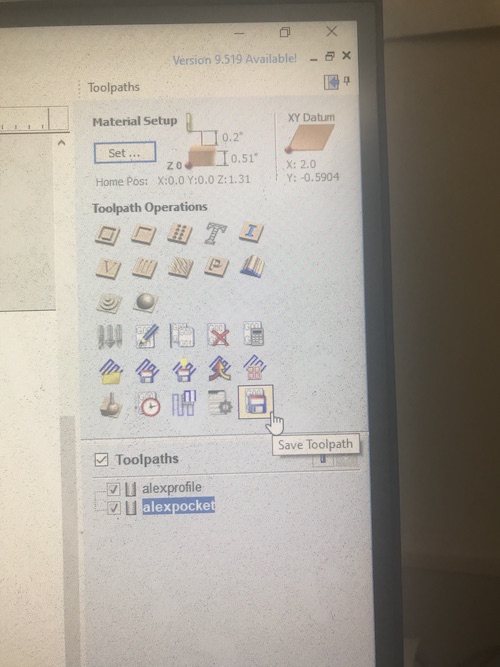
You can see here that this is the setting I had to change before saving the toolpath for my pocket cut:
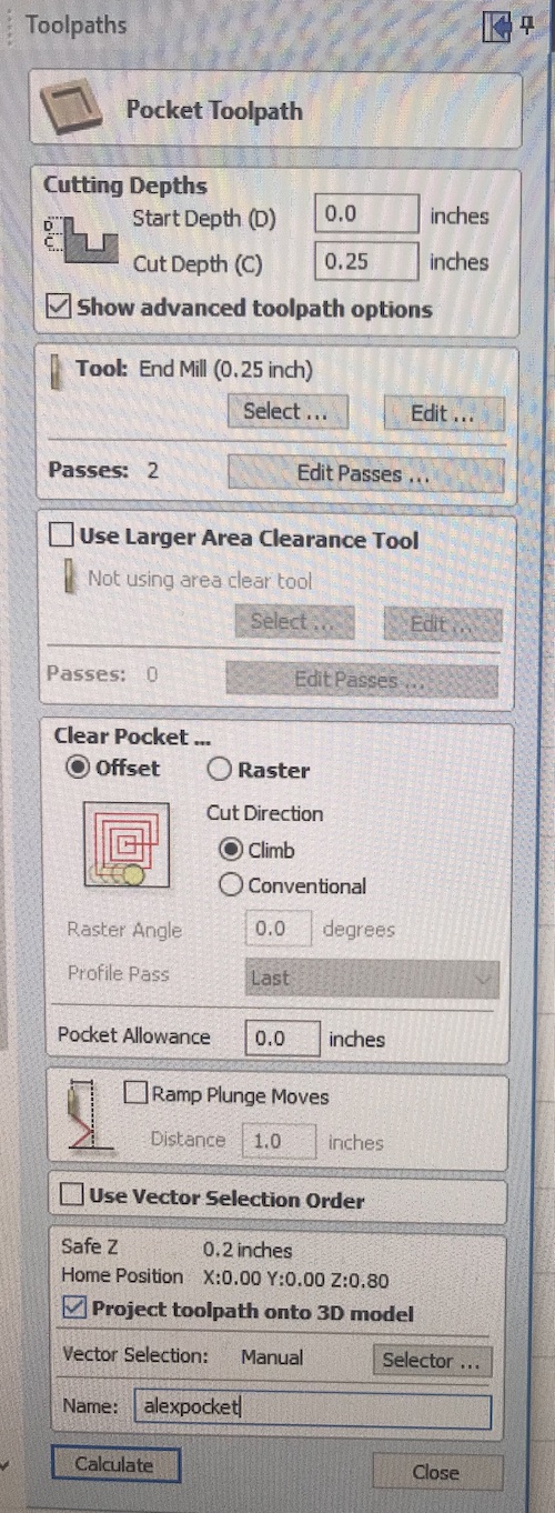
Here are my settings for the pocket cut and Shopbot cutting it:
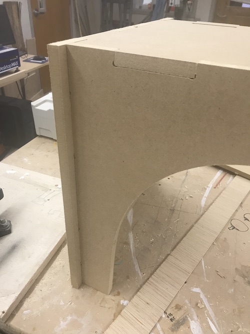
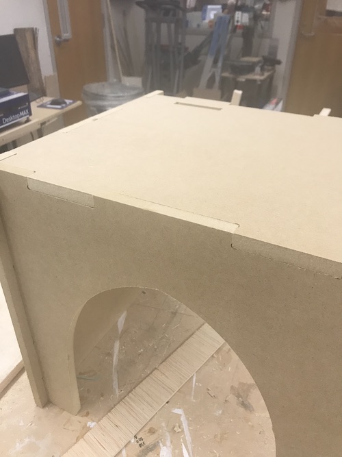
As the pocket was being created, I began putting my other pieces together. The clearance was spot on they fit together perfectly!
Here was the pocket cut (before and after I vacuumed it) and the Shopbot cutting the profile cut. I used the same settings as before for the profile cut.
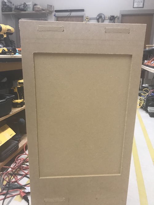
Here is the right piece:
I ran out of MDF for the back piece (because I had initially forgotten it) so I cut it separately using the same profile settings. Here are all the pieces on one file with the toolpaths calculated:
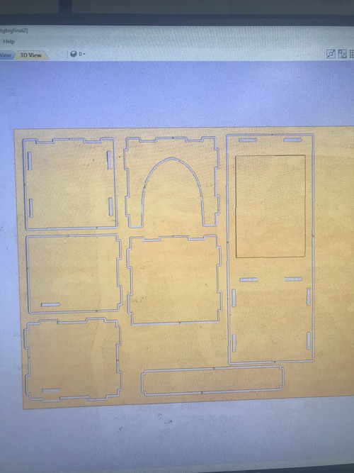
In order to save the toolpaths, I clicked this icon. I made sure to name them with my name and what kind of cut they were.
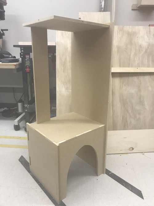
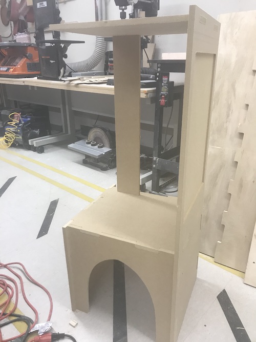
Here is the finished product! I hope my cat likes it because I put a LOT of time and effort into this.
Overall, this week I gained more comfort using parameters and navigating Fusion. I learned the importance of clearance, in addition to a new way of getting my design from Fusion to Aspire. This week was cool because the Shopbot can produce a lot of practical and common objects (furniture, etc), so it was very useful to learn how to use. I feel more confident about using the Shopbot and creating toolpaths appropriately.
To download my files for this week, click here.
Group Assignment
The group assignment for this week was the test runout, alignment, speeds, feeds, and toolpaths for our machine. My individual contributions included defining the aforementioned terms, generating the toolpaths for the test files, and cutting and analyzing the test files. You can view the whole process on our group page here.