14: networking & communications
Individual Assignment
The individual assignment for this week was to design, build, and connect wired or wireless node(s) with network or bus addresses.
RS-232
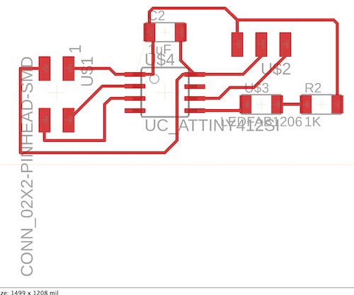
I decided I wanted to try making the RS-232 bridge and node boards. I used Neil’s bridge and node board designs to create mine. I first designed the bridge schematic and board, then simply took out the FTDI connection for the node boards. Here are my schematic and board files:
Bridge:
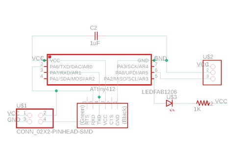
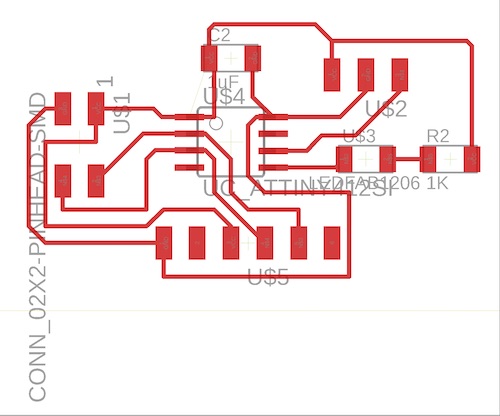
Node:
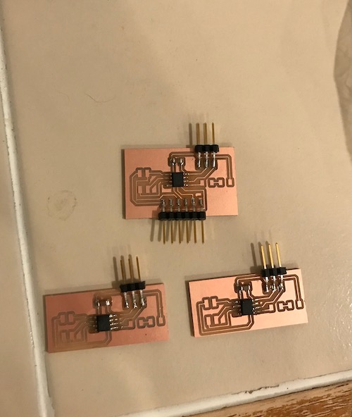
I realized that I was missing some parts whenever I soldered my boards. I needed the 1K resistors, LEDs, and 2x2 pin headers. I went ahead and soldered everything else, and decided that I could try and start programming my boards until I obtained those parts. Here is what the boards looked like at that point:
I started the programming portion by downloading Neil’s C code. It definitely felt pretty intimidating upon first looking at it. The basis of the code was that each board had an ID, the bridge or master board being node 0, and the slave or node boards being 1 & 2. Whenever a node’s ID was typed into the serial monitor, all the nodes would blink once but that specific node would blink twice.
I first uploaded a simple Blink code to my bridge board to check that the LED was working and everything was routed correctly. I realized I had made yet another mistake on my board, connecting the LED to both a pin and VCC, so I cut the trace leading to VCC and wired it to ground. Because I used the same schematic for all of my boards, I had to do this with my node boards as well. Once I fixed the boards, I uploaded the code and the bridge and one of the node boards worked:
insert embedded youtube vids here
Whenever it came to the software side of things, I was not sure how to change Neil’s code to work for the ATtiny412 that I was using. I asked one of my instructors, Dr. Harris, who explained how to change the ports and directions according to the what pins the LEDs were connected to. He explained to me what PB# and DDRB meant and what the ‘and’ and ‘or’ functions did. When it came time to alter Neil’s code to work for the 412, I began by changing the port, data direction, and pins. I compared the pinouts for the ATtiny45 and the ATtiny412:
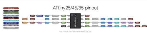
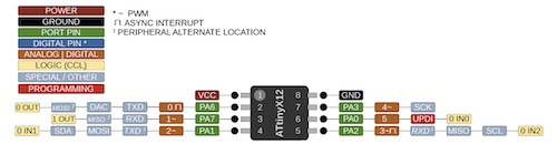
While the 45 uses Port B, the 412 uses Port A. My LED was connected to PA2, so I changed it to #define led_pin (1 << PA2). In addition, I made
#define led_port PORTA
#define led_direction DDRA
and
#define serial_port PORTA
#define serial_direction DDRA
I began receiving errors when it came to changing the serial pins. I made
#define serial_pin_in (1 << A6) //tx of ftdi
#define serial_pin_out (1 << A7) //rx of ftdi
Because those were the pins for TX and RX on the 412. This spit out the error cannot convert 'PORT_t* {aka PORT_struct*}' to 'volatile unsigned char*' for argument '1' to 'void put_char(volatile unsigned char*, unsigned char, char)’. After playing around with the code some more in an attempt to get around the errors, I decided to ask one of my instructors, Dr. Harris, for help. Dr. Harris did some research and enlightened me on the fact that the ATtiny chips do not use the same keywords for inputs and outputs and that the Attiny412 had a different syntax than the previous Attiny chips. This was not ideal. Dr. Harris recommended that I use Arduino and convert Neil’s code into Arduino inputs and outputs to carry out the same functions of Neil’s circuit. He also provided me with two options, which were as such:
Option 1: The AAttiny412 has a hardware UART. I should be able to just use that to connect to the FTDI. Then use software serial to communicate to two other Attiny45 boards running Neil’s code.
Option 2: Instead of using Neil’s software Serial code, use the arduino softwareSerial library, but I’ll need to manually change the pinMode inside his IF statement in his While(1) loop in place of his output( ) and input() functions. It involves replacing the code he has with other code that implements the INTENT of his functions.
output(serial_direction, serial_pin_out); becomes pinMode( serial_pin_out , OUTPUT);
and input(serial_direction, serial_pin_out); commands become pinMode( serial_pin_out , INPUT); etc.
While both of these options seemed viable, I decided that I wanted to prioritize working on my final project in the interest of time. I decided that I would take another approach to networking and communications week. If I had time in the future, I would return to this.
I2C
The route I decided to take for networking and communications week was I2C. I did not know what I2C (or I²C) was, so I read a bit about it here.
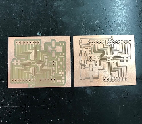
When it came to creating the PCB boards, I chose to modify a board called a Satshakit so that it would act as an Arduino Uno. You can read about what a Satshakit is and download its corresponding files here. I decided I wanted to mill two modified Satshakits, one that would act as the master and the other as the slave. I downloaded the .zip file and opened the schematic and board files for the satshakit cnc.
To modify the satshakit, I decided to delete the LED that was not connected to power and its corresponding resistor. I liked the idea of having an LED connected to power that way I would be able to immediately tell if it was working, but I decieded that I did not need the other LED because I would not use and it it would draw power unecessarily. I additionally moved some of the capacitors so they would be easier for me to solder. They were a little close together so I simple moved one a bit further away. As a final touch, I added “M” and “S” to the boards so I would know which board was the master and slave. How schwifty. Once these files were saved, it was time to mill and solder the boards!
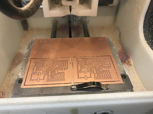
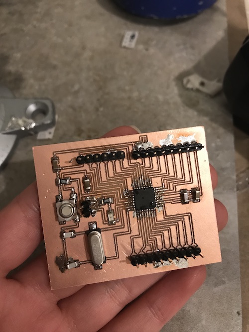
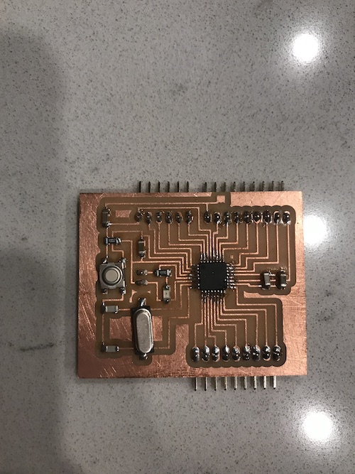
Here are my milled boards (they turned out so well!):
I decided to solder and program one board first, just to make sure it worked. Here is my finished soldered board:
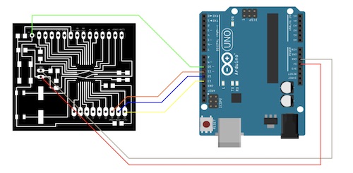
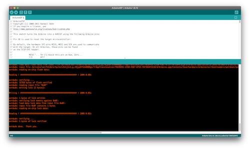
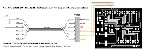
The next step was following the instructions to make it function as an Arduino. I first got an Arduino and uploaded the Arduino ISP sketch provided by Arduino. I made sure the board was an Arduino UNO and the correct port was selected. Once the sketch was uploaded, I used this diagram to connect the satshakit to the Arduino:
The Github provided the remaining instructions:
Once everything is connected, follow these steps to upload Arduino bootloader:

1) open Arduino IDE
2) select proper programmer (for example Arduino as ISP or USBtinyISP)
3) select Arduino UNO as board
4) click on tools->Burn Bootloader
I connected everything and plugged in the Arduino. I saw that the power LED turned off whenever I connected 5V of the Arduino to my satshakit. This was an issue. This stopped me from burning the bootloader. After examining my board and testing my connections, I found that my satshakit had a TON of shorts. There were many connections that should not have been connected, which was a big problem. It was almost impossible to narrow down exactly where I went wrong with my soldering, but one of my instructors, Mr. Rudolph, pointed out that not only had I not sanded my board nearly enough before soldering it, but the traces were very close together and as such it was very easy to make mistakes while soldering. This being said, I realized it was probably easier to remill another board and take different precautions than to try and fix this one. RIP failed board #1!
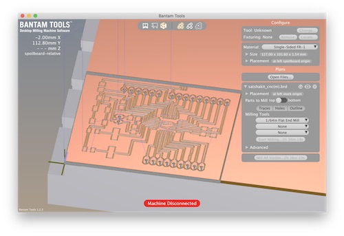
So in order to avoid making another failed board, Mr. Rudolph showed me some hacks he uses to create boards. He advised that I downloaded Bantam Tools on my laptop, so that I could check to make sure everything would mill correctly before transferring the files to our lab’s PCs. You can download Bantam Tools here. After installing it, I uploaded my .brd file of my master board. I originally milled the traces with a 1/64” bit and the holes and outline with a 1/32”. You can see what the file looked like here:
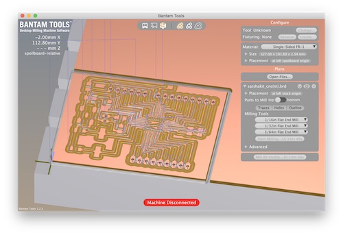
Mr. Rudolph suggested that I use the 1/64” only for the parts that needed to milled with a small bit. He advised additionally using a 1/32” and 1/16”. This would increase the distance between the traces and clear out extra copper that could cause issues when soldering. You can see that there is a lot more room. Here is what that looked like:
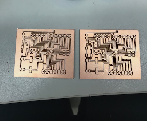
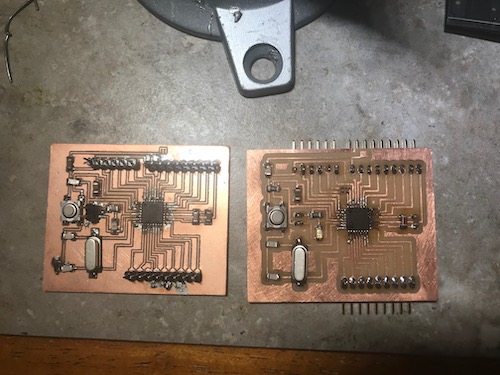
I milled two of these files and changed the bits when prompted. The next adjustment I needed to make was the level of sanding. I was really scared I was going to rip a trace if I sanded it too hard, so I barely sanded it. Mr. Rudolph assured me that as long as I was careful, I could apply a good amount of pressure and be fine. It was important to get the copper shavings off and any strands that could mess up the board. After a good bit of sanding, the boards were ready. You can see my old board and the new one side by side. The new one looks a lot better:
Next, it was time to solder again. The increased distance between the traces also made it a lot easier to solder. Additionally, I changed the type of pin headers I used so they would be under the board because it was easier to solder this way. Here is my final soldered board and the old and new board side by side:
Now it was take 2 of programming the satshakit. The Arduino already had the sketch uploaded to it, so I connected the satshakit and attempted to burn the bootloader. It worked!
My satshakit could now function as an Arduino. This being said, the following step was uploading code onto it. For this assignment, I chose to use the Master Writer/Slave Receiver from Arduino to have the slave board display in the serial monitor what the master was telling it to. I decided that I wanted to test the code with my satshakit and an Arduino first before going straight to two satshakits. I chose to make my satshakit the master and the Arduino the slave. I uploaded the slave code to the Arduino:
// Wire Slave Receiver
// by Nicholas Zambetti <http://www.zambetti.com>

// Demonstrates use of the Wire library
// Receives data as an I2C/TWI slave device
// Refer to the "Wire Master Writer" example for use with this

// Created 29 March 2006

// This example code is in the public domain.


#include <Wire.h>

void setup()
{
  Wire.begin(4);                // join i2c bus with address #4
  Wire.onReceive(receiveEvent); // register event
  Serial.begin(115200);           // start serial for output
}

void loop()
{
  delay(100);
}

// function that executes whenever data is received from master
// this function is registered as an event, see setup()
void receiveEvent(int howMany)
{
  while(1 < Wire.available()) // loop through all but the last
  {
    char c = Wire.read(); // receive byte as a character
    Serial.print(c);         // print the character
  }
  int x = Wire.read();    // receive byte as an integer
  Serial.println(x);         // print the integer
}
I made the baud rate 115200. That was just about the only change I felt I needed to make, though once I saw it was working I figured I could play around with the code a bit and change the characters/integers. I then needed to upload the master code to the satshakit. To do this, I needed to connect an FTDI chip to the satshakit according to this diagram:
Here is the code:
// Wire Master Writer
// by Nicholas Zambetti <http://www.zambetti.com>

// Demonstrates use of the Wire library
// Writes data to an I2C/TWI slave device
// Refer to the "Wire Slave Receiver" example for use with this

// Created 29 March 2006

// This example code is in the public domain.


#include <Wire.h>

void setup()
{
  Wire.begin(); // join i2c bus (address optional for master)
}

byte x = 0;

void loop()
{
  Wire.beginTransmission(4); // transmit to device #4
  Wire.write("x is ");        // sends five bytes
  Wire.write(x);              // sends one byte
  Wire.endTransmission();    // stop transmitting

  x++;
  delay(500);
}
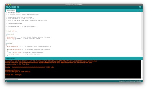
I uploaded it and it worked!
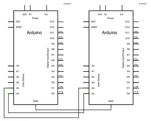
Now, I needed to connect the Arduino and satshakit and open the serial monitor to see if the slave board was indeed receiving. I did this by keeping the FTDI chip connected to the satshakit and following this diagram for the rest. Basically, I had to connect A5 (the serial clock pin) and A4 (the serial data pin) to each other in addition to GND.
After connecting them together, I opened the serial monitor and saw… nothing. It was not working. The sketches had both been uploaded successfully, and my wiring was correct (I as pretty sure), so I was not sure why I was not seeing things on the serial monitor. I double-checked my connections and reuploaded the sketches. Finally, I decided to replace my satshakit with an Arduino to see if the code would work. I hooked up the ground pins, A4, and A5, and connected each Arduino to a different PC. It worked:
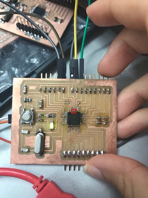
From this, I was able to deduct that there was an issue with my satsha kit. I decided to take a multimeter and check my connections. Aha! There was a tiny, tiny solder bridge between these two pins. I removed the bridge and reconnected it to the Arduino. It worked!
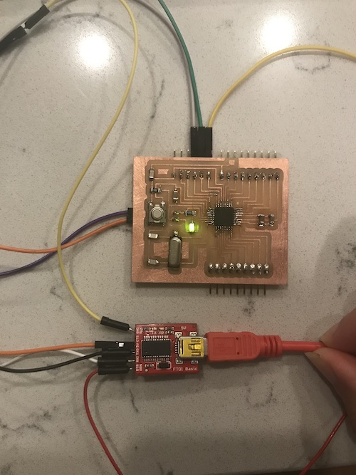
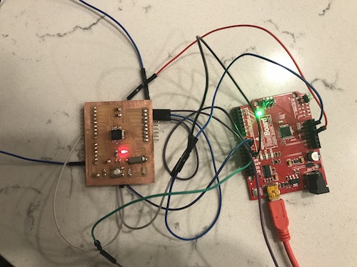
Here was my setup:
Now that I knew my satshakit and the code worked, I needed to solder the other one and code it as the slave. Here is the soldered board. It took a lot less time and came out really well the first time through.
I then needed to follow the same instructions as before to burn the bootloader to get it to function as an Arduino UNO. I reuploaded the ArduinoISP sketch to my Arduino, then connected my satshakit and burned the bootloader. It worked!
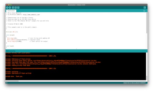
I proceeded to connect it to the FTDI chip to upload the slave receiver code. I made sure my wiring was correct, in addition to the board (Arduino UNO) and port. The sketch uploaded successfully:
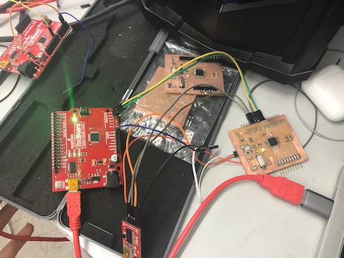
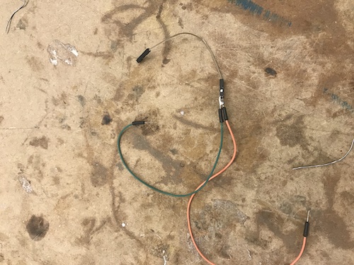
Finally, I could hook up the satshakits together to see if the master was communicating with the slave. I had to use two FTDI chips,which meant that the boards needed to be connected to GND in two spots. One of my peers, Harri Seto, allowed me to use a contraption he made of three wires soldered together. He suggested I create another one to use for my other board. This would allow me to plug in one end to the board, one to the FTDI chip, and one to the other board.
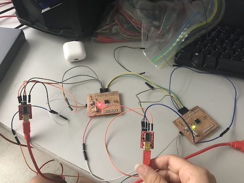
Here was my final setup and a video of it working! The master board has the green LED and the slave has the red LED.
This week, I learned how to get two boards to communicate. This week was definitely one of my longest weeks to work on because it was something I had never even been close to doing before. Though I did not ultimately use RS-232, I learned why it was more difficult to use the Attiny412 as opposed to the Attiny45. In addition, I was able to look at the codes for the master and slave boards and look at what the master was telling the slave to do and how the slave was able to do it. Most importantly, I learned techniques for how to better my board production in the future.
To download my files for this week, click here.
Group Assignment
The group assignment for this week was to send a message between two projects. You can view the whole process on our group page here.