Frame
Concept
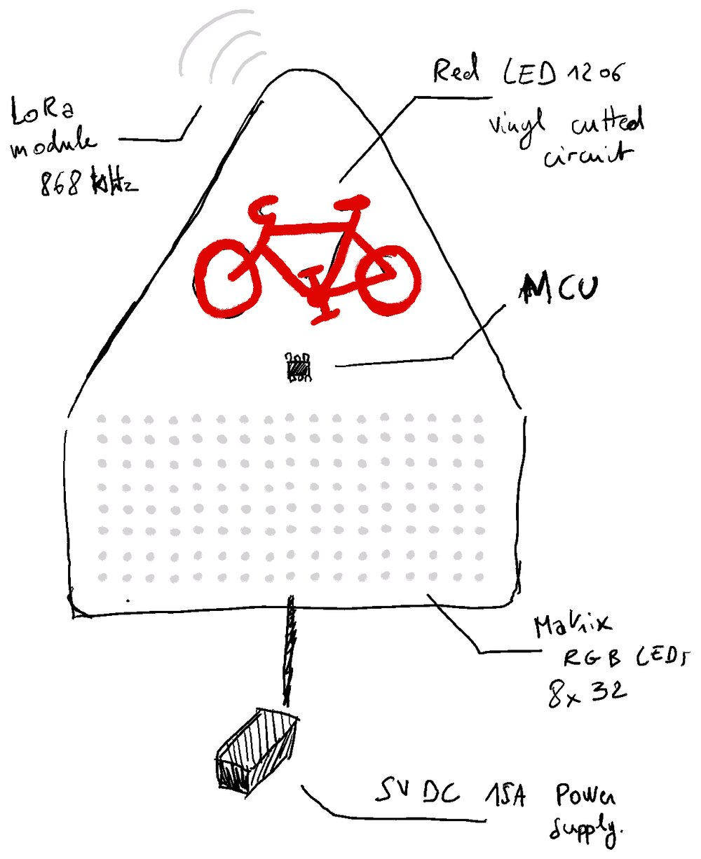
Here are the basic components in the Traffic sign, to alert that a bike is coming.
CAD
A first proposition for the Traffic Sign bike. Here are the physical components of the sign:
- Top layer, in aluminium with a reflective top (1.5mm)
- A full glass acrylic layer of 2mm
- En LED enclosure layer (2) in plywood (5mm)
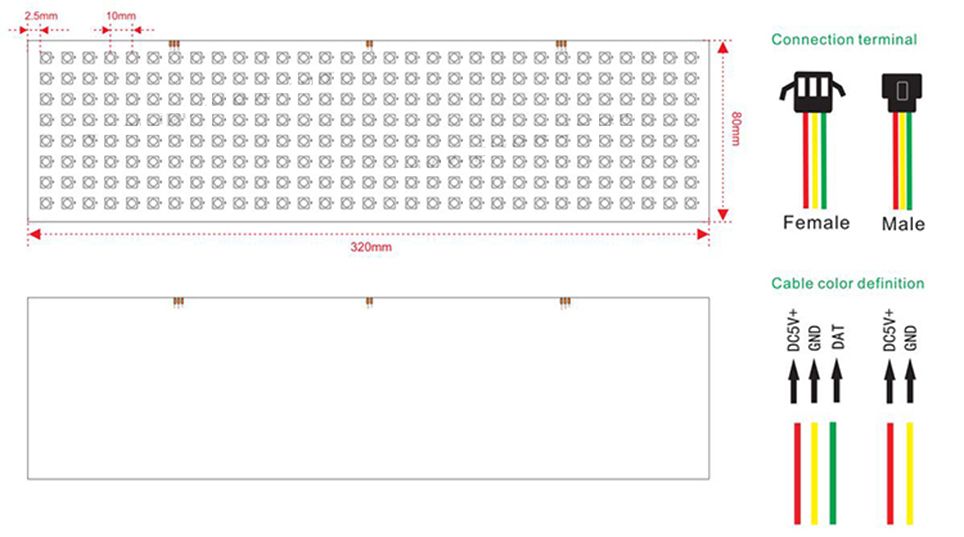
- A Matrix LED. 8x32 (WS2812b)
- A bike in Red LEDs
- An aluminum layer (3), support for the LEDs (heat dissipation)
- Behind this layer, a board with MCU to command the LED and a LoRa module to receive the information
- Board enclosure layer (4) in plywood (5mm)
- A last finishing back layer (5) in plywood (5mm)

So first I download a picture of a French Bike Traffic Sign and redraw a parametric bike on top of it.
source zedfy.shop
Knowing the dimension of the Matrix LED I wanted to use, I needed to create some holes to let the light pass through the aluminium layer.

Each hole has a diameter of 5mm as it's the size of the ws2812b led.

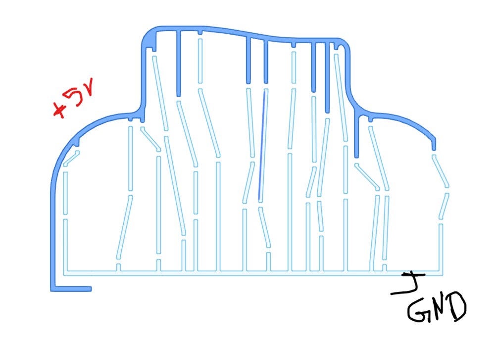
After the first aluminum layer and the acrylic, I have a thick layer that will let me put the components of the light and also put the LoRa antenna, and I started to think about the hole to pass different bolts to fix the layer together and also the Sign to a pole.
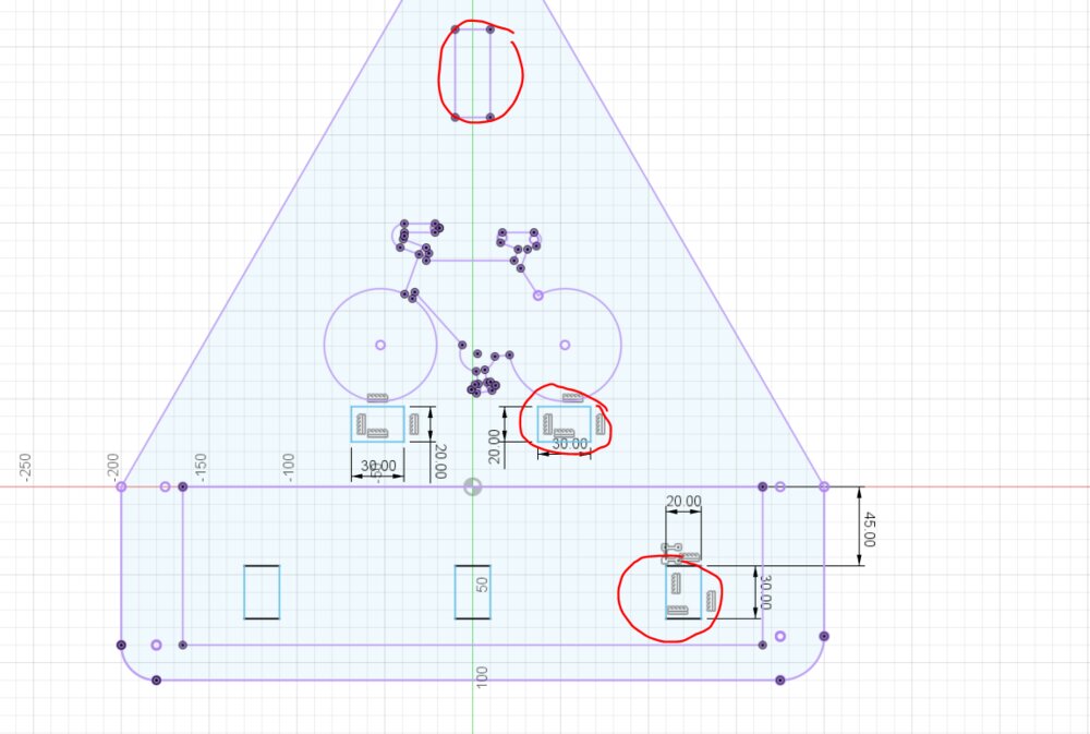
Then there is another aluminum layer. On the front, it will hold the matrix LEDs and the bike LEDs, then there are some holes to let the wires pass through the rear of the layer that will hold the MCU and the LorA module.
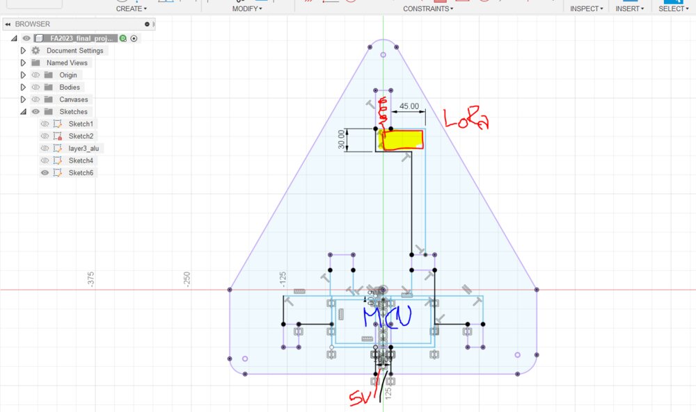
As the first layer of plywood, there is a second one to have some room to put all the components and let an entrance of the power supply wires.

Some of the transformations needed to be made after the drawing of the layers. Like for example the hole between the layers to fix them.
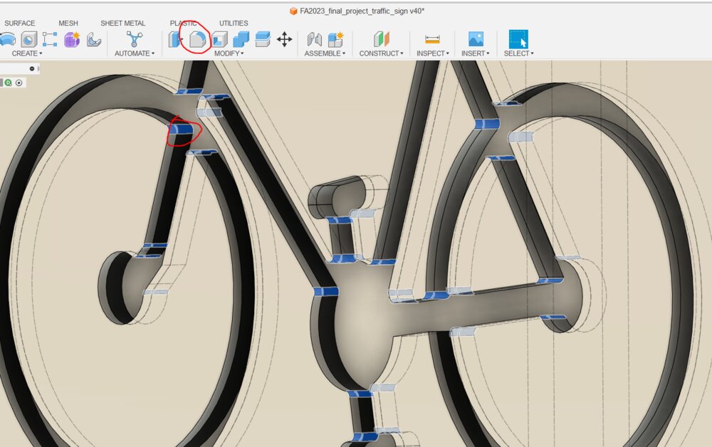
Or when a added a round fillet to the corners when I decided to use the plasma CNC cutter instead of the CNC milling machine.
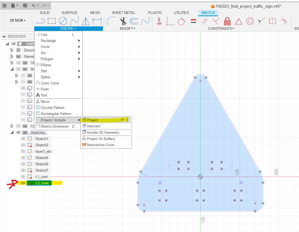
The layers will be cut with 2D machines: plasma and laser cutting machines. They need clean DXF files to generate the toolpath. So I recreated some sketches that are just a projection of the different faces of the Sign. So the DXF is cleaner than the original one with all the constraints but still connected to it. So if I change anything the sketch will be changed too.
Even if I used Fusion 360 to create the Bike LEDs PCB, I decided to documented it on the Electronic section, so it can be found there.
Plasma cut of aluminum.
The first layer and the 3rd one will be in aluminum. They are the more complex to make so let's start with them.
I wasn't sure, at first, to go with the plasma cutter, after the result the Wild Card week. So I did a first try with the CNC, but the aluminum sheet became so hot that it began to warp.

So back to FastCAM. I start with the first layer. I choose a kerf or as on the Wild Card week, the value of wasn't enough.

I try to cut the first layer, but it stopped after the bike cut with an 0-30 error on the plasma station. After having a look at the Hyperthem documentation, it happen that the electrode was too worn out.
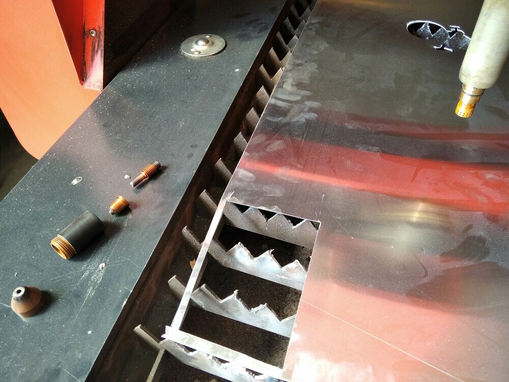
We have some consumables, so I changed it.

It looks great! The plasma is soo quick to cut this aluminum sheet. I then cut the second aluminum layer.
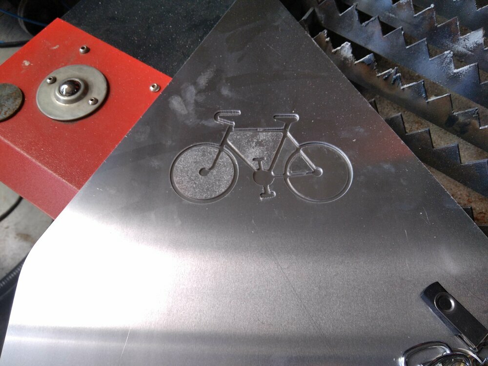
When I put the two layers on top of each other, it's a match!
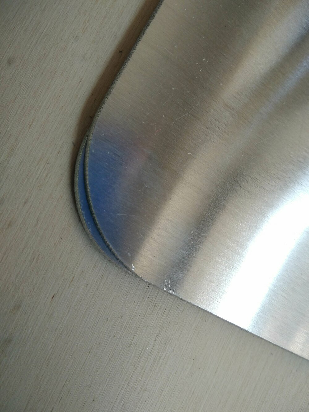
... but ... When I reverse one of them, the bottom corners no longer match.
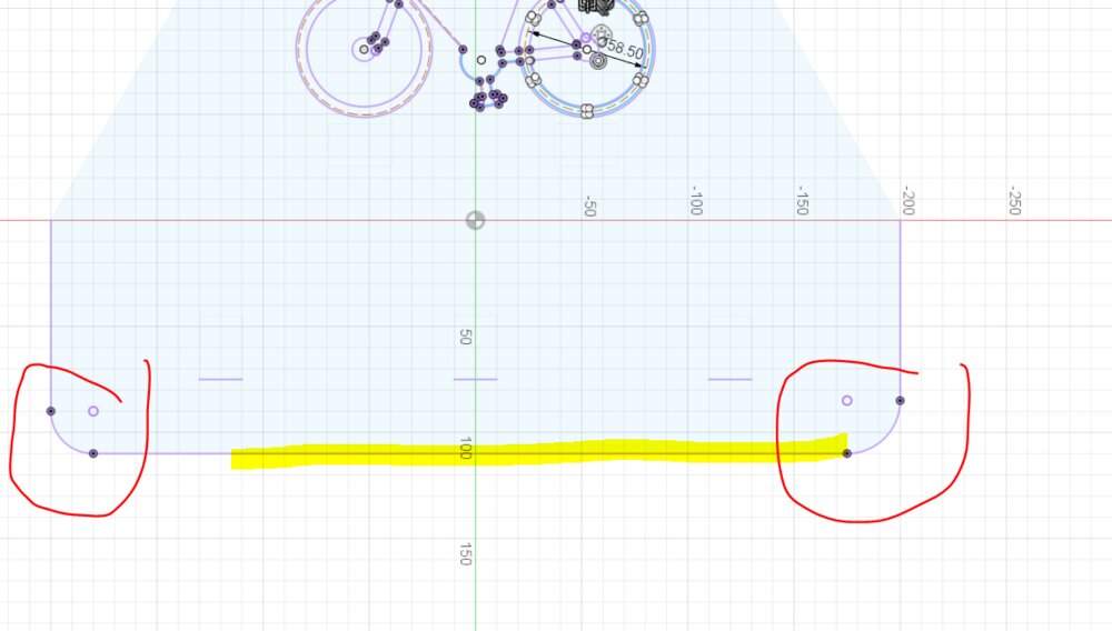
It looked like I didn't constrain well my sketches. When moving something (I don't know what) the corners have changed. As I don't have enough time, I'll let it like this. I may go for a v2 with a more clean aluminum sheet cut.
CNC milling the aluminium layer
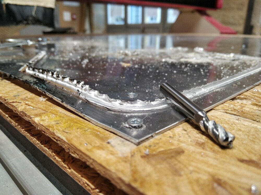
The lateral cutting was a failure, but for vertical drilling of small holes, the CNC remains the ideal tool.

As my layers are already cut, I need to properly set the origin. So in the CAM of Fusion 360, I design an inner contour to cut into some wood, to be able to set the aluminum triangle into it.
I just use some thin leftovers. I just need the corners to be in the wood not all of it.
I then use another piece of wood, a bit stronger, to fix the triangle (using the holes into the frame of the screws).

Because of the piece of wood, I had to change the retract height of the tool to be sure it won't hit the wood during his job.
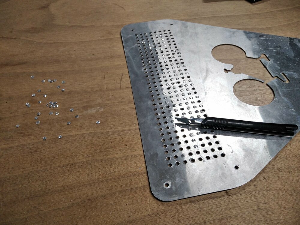
The milling went well. Even if the sheet is wrapped a bit. I didn't want to burn the sacrificial layer on the bottom, I set the final step down to the thickness of the aluminum sheet. As the aluminum welt a bit, some holes were not pierced. So I had to remove what was left manually with a cutter.
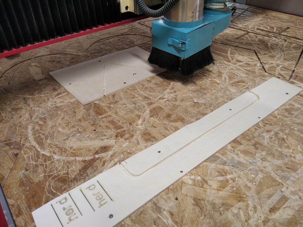
Laser Cut the wood players

4 layers are cut with the laser. 3 are in plywood (5mm) and 1 in acrylic glass. To have a clean DXF file I decided to create new sketches in fusion and I used the projection function du get the layer's face. And then export the sketch in DXF.
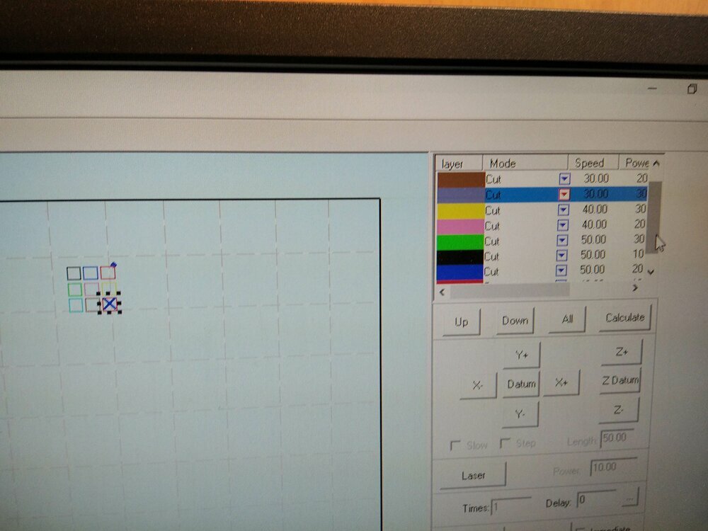
I knew the parameters for cutting 5mm plywood (cfr. week3). But I had to do some tests for the glass acrylic.
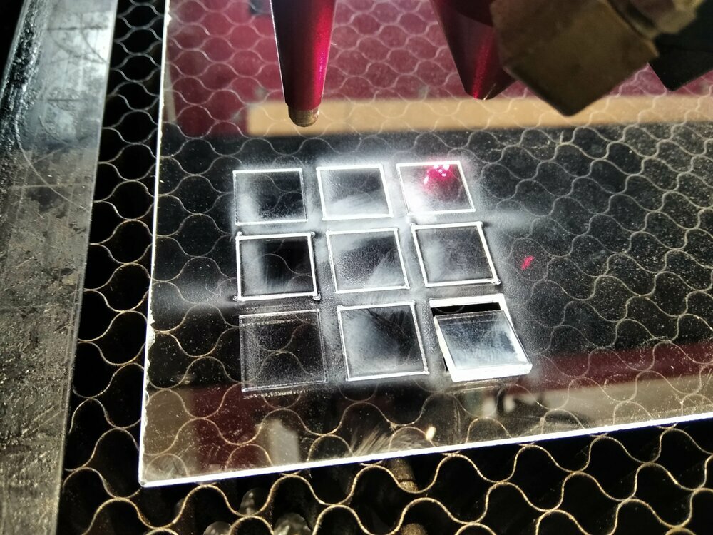
So here I can see that and (speed and power) are the parameters to cut, and the and are already good to mark (I'll mark the bicycle draw on it).
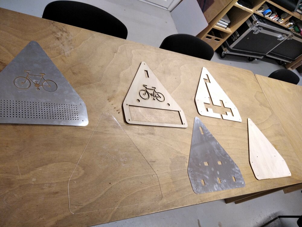
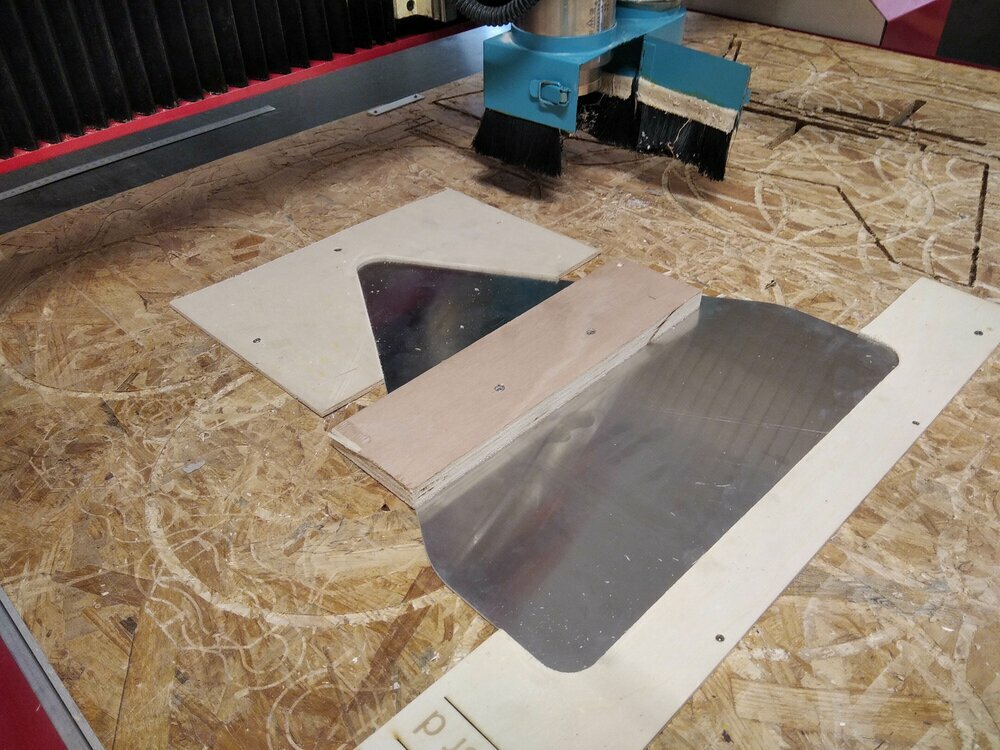
So here are all the layers cut. (Plasma cutting pieces include)
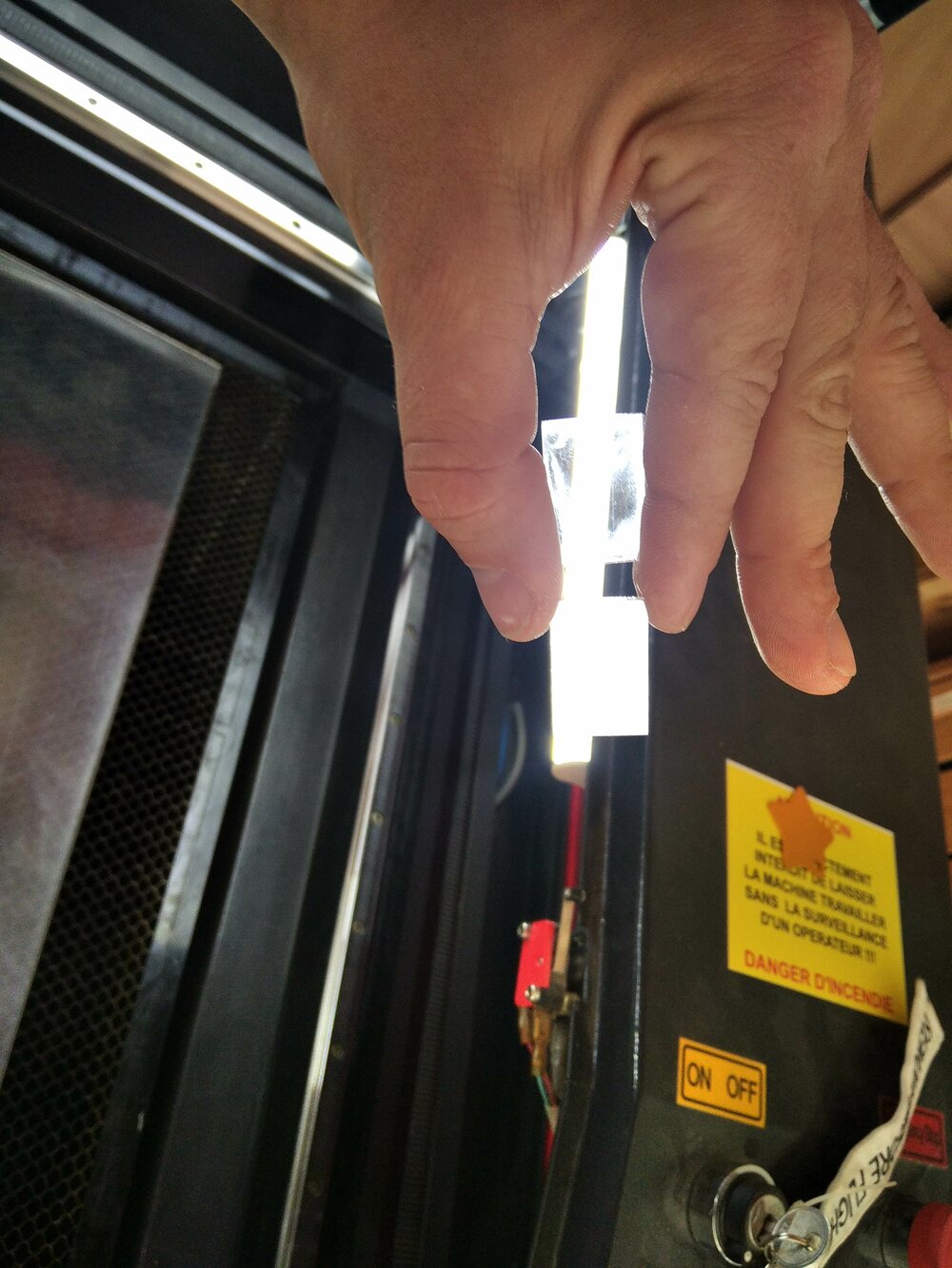
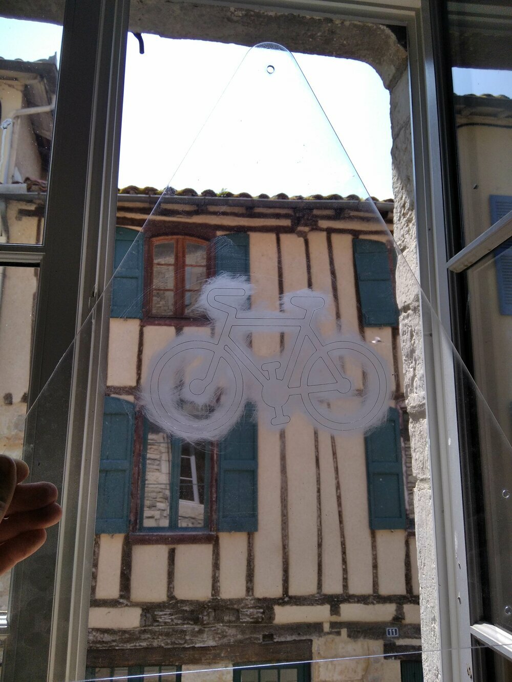
I want a more *diffuse light behind the "bike LED". So the idea is to sand a bit the acrylic to help with that. Here is the first test we can see the difference.
And here we go. I have now all the parts of the frame. Let's go for the electronics.
Files
Here is the view of the Fusion 360 file for the frame. You can download here.
Here are the other files I used to make the frame: