Electronics
Graph
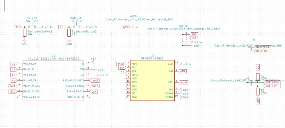
As I did for the Traffic sign, I drew the graph with the link of all the components for the Wally board.
Design the board
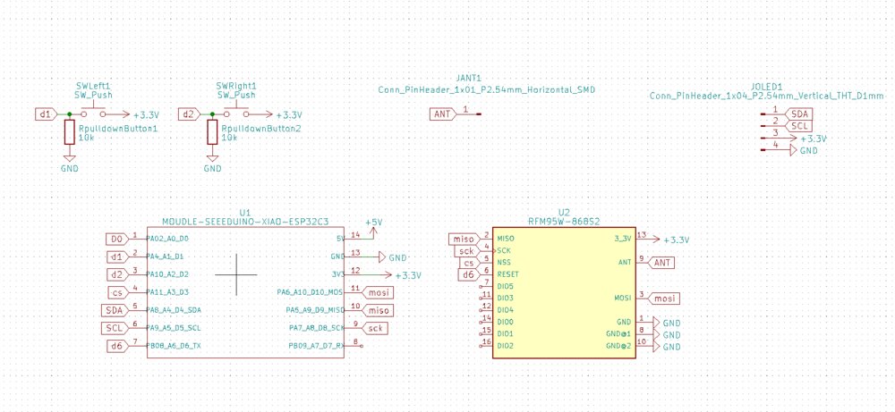
So this board is somehow close to the one I design [on week6]/weekly-assignments/week06#lets-design-the-schematic-of-the-board). Just the SPI pins will be connected directly on the board to the LoRa Module. The I2C pins will be exposed for the OLED display. Then I added 2 buttons to be able to interact with the board. And a pad to solder the LoRa antenna. I added an addressable LED for fun.

I succeed to design a single-layer board.
Electronic production
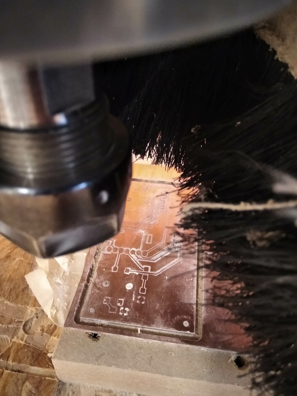
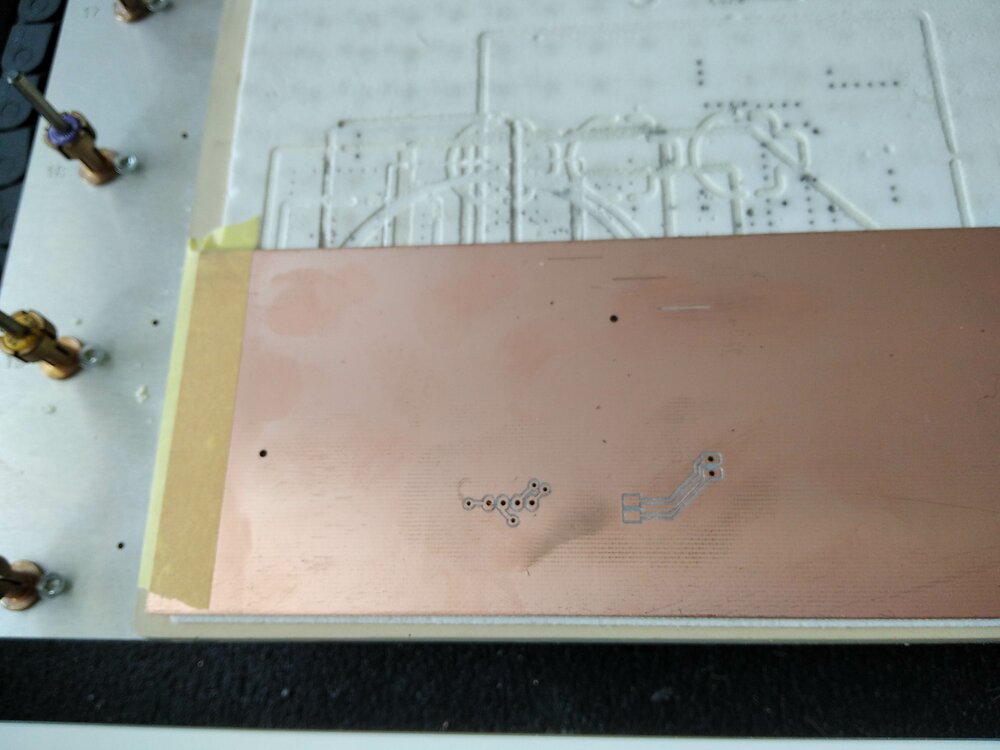
Same as during week8, I used FlatCAM to produce my board. But after the finish, I realized that the inner EdgeCut wasn't cut!
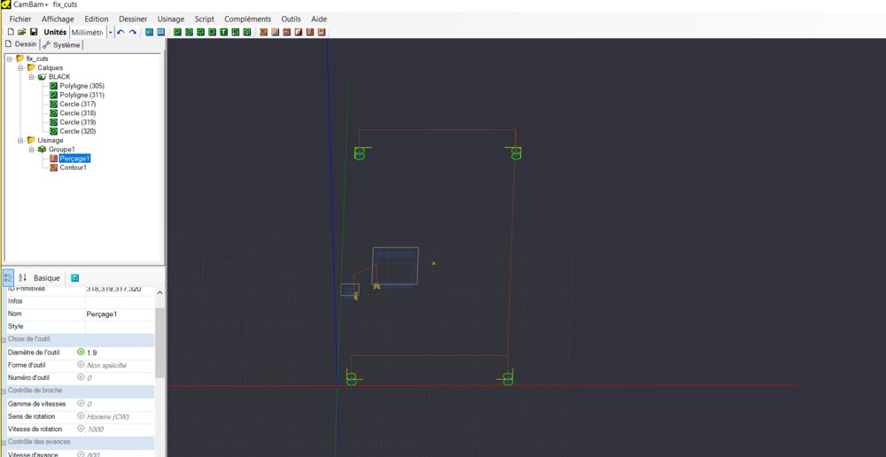
After looking for the problem, I realized that the inner Edgecuts are not supported in FlatCAM as seen by a previous student. While the CNC was still with the correct origin, I quickly export the DXF for the Edgecut in CamBam to generate the GCode to cut the inner hole I want below the ESP32 to be able to solder the wires of the battery.

And here we go, it's not perfect, but compare to my first-ever board produce, it's not that bad.
I forget to take a picture of the board soldered. But no worries, I may some mistakes, so there will be other boards to see ;-).
Code the ESP32C3
So I have a board that can speak to a LoRa module with the SPI protocol, an OLED display through I2C and two pushbuttons. But I need to connect them to my needs with some programs.
Listen to the switch button and show it on the Display
As for the Traffic Sign, I'll first use Wokwi to simulate some behaviors.
So first a quick code for the buttons.
#define BTN_LEFT 1     // button left pin
#define BTN_RIGHT 2    // button right pin

// variable for reading the pushbutton status
int buttonStateLeft = 0;
int buttonStateRight = 0;
void setup() {
    Serial.begin(9600);
    delay(4000);
    pinMode(BTN_LEFT, INPUT);
    pinMode(BTN_RIGHT, INPUT);
}

void loop() {
    // read the state of the pushbutton value:
    buttonStateLeft = digitalRead(BTN_LEFT);
    buttonStateRight = digitalRead(BTN_RIGHT);

    // check if any of the pushbuttons are pressed. If it is, the buttonState is HIGH:
    if (buttonStateLeft == HIGH || buttonStateRight == HIGH) {
        Serial.println("Wally !!");
    }
}
Now, it would be nice to show something on the OLED with I2C. For that, I will use the two libraries of Adafruit: GFX and SSD1306
#include <Wire.h>
#include <Adafruit_GFX.h>
#include <Adafruit_SSD1306.h>

#define SCREEN_WIDTH 128 // OLED display width, in pixels
#define SCREEN_HEIGHT 64 // OLED display height, in pixels

// Declaration for an SSD1306 display connected to I2C (SDA, SCL pins)
#define OLED_RESET     -1 // Reset pin # (or -1 if sharing Arduino reset pin)
#define SCREEN_ADDRESS 0x3C ///< See datasheet for Address; 0x3D for 128x64, 0x3C for 128x32
Adafruit_SSD1306 display(SCREEN_WIDTH, SCREEN_HEIGHT, &Wire, OLED_RESET);

#define CURSORS_X   30
#define CURSORS_Y   10

void setup() {
    ...
    // SSD1306_SWITCHCAPVCC = generate display voltage from 3.3V internally
    if(!display.begin(SSD1306_SWITCHCAPVCC, SCREEN_ADDRESS)) {
    Serial.println(F("SSD1306 allocation failed"));
    }
    display.setTextSize(2);      // Normal 1:1 pixel scale
    display.setTextColor(SSD1306_WHITE); // Draw white text
    display.setCursor(CURSORS_X, CURSORS_Y);     // Set the Start
    display.display();
    delay(2000); // Pause for 2 seconds

    // Clear the buffer
    display.clearDisplay();
}


loop() {
    ...

    // check if any of the pushbuttons are pressed. If it is, the buttonState is HIGH:
    if (buttonStateLeft == HIGH || buttonStateRight == HIGH) {
        display.clearDisplay();
        display.setCursor(CURSORS_X, CURSORS_Y);
        display.print(F("SIGNAL"));
        display.setCursor(CURSORS_X+15, CURSORS_Y+30);
        display.print(F("SENT"));
        display.display();
    }
}
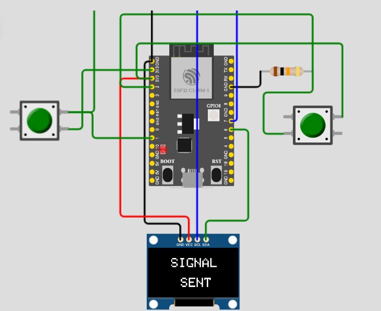
And here we go "SIGNAL SENT" when one of the buttons is pushed.
Sent LoRa Signal
So now it's time to add some LoRa signals. I'll start with the code I made in week13.
#include <SPI.h>
#include <LoRa.h>

#define SS 3 //=D3

void setup() {
    ...
    Serial.begin(9600);
    delay(4000);

    Serial.println("Wally !!");
    LoRa.setPins(SS);
    while (!LoRa.begin(868E6)) {
        Serial.println("Starting LoRa failed!");
        delay (1000);
    }
}

void loop() {
    if ((buttonStateLeft == HIGH) && (!msgSent)) {
    ...
        // send packet "bike" to the network.
        LoRa.beginPacket();
        LoRa.print("bike");
        LoRa.endPacket();
    }
}
Here we go we should be able to send a LoRa signal already, but we can't test it on Wokwi, so before testing on the board, I'll add an interval of time to remove the Signal Message on the screen after 3 seconds but without the delay() like in the Traffic Sign code.
unsigned long previousMillis = 0;  // will store last time LED was updated
const long interval = 3000;  // interval at which to blink/switch words (milliseconds)
bool msgSent = false;  // store state about the message

void loop() {
    ...

    // check if any of the pushbuttons are pressed. If it is, the buttonState is HIGH:
    if ((buttonStateLeft == HIGH || buttonStateRight == HIGH) && (!msgSent)) {
        ...

        msgSent = true;
        previousMillis = millis();
        buttonStateLeft = LOW;
        buttonStateRight = LOW;
    }
    if(msgSent) {
        unsigned long currentMillis = millis();
        if (currentMillis - previousMillis >= interval) {
            display.clearDisplay();
            display.display();
            msgSent = false;
        }
    }
}
And it's working !!! =D Final project here I am!
Errors and Bugs
SPI connection with XIA ESP32-C3

After pushing the code to the board, once restarted and with the LoRa Module connected, the code wasn't working anymore, and no serial message was sent through USB. With Ahmed, we spent almost 3 days trying to find the origin of this bug (we look for software and hardware issues). We never found the answer. I need to create a post on the Seed Studio Forum, because at the end we think the issue may be from the design of the XIAO ESP32-C3.

I had to finish the project, so the only solution I had is to replace the XIAO ESP32C3 with an XIAO SAMD21. The footprint is exactly the same and the pinout is close enough, no need for a new board.
Board Design
The week before the final presentation, I finally had the opportunity to go to the Fablab of Kamp-lintfort, my node. So I saw my instructor in real for the first time. Have a nice week there! I went with all my project production, and I had a week to finish it.

My board and all its components were soldered, but I didn't add the chance to test it before arriving at the Fablab of Kamp-Lintfort. I quickly see a big problem: one track, the 3.3V was missing. So I went back to the design.
If I had the chance to reproduce the board better to redesign and add some features. I added some pins for the battery for a more clean connection. Knowing the problem there was with the SPI connection, and talking with Ahmed, I removed the connection with the TX and RX pinout of the ESP32 and used the D4 as CS for the SPI protocol and removed the RESET connection of the LoRa module.

At the Lab in Germany, they have an LPKF ProtMat to produce PCB. With this machine, making a double-layer PCB is much easier. The XIAO Board has some pads at to bottom of the board, so I try to remove as much as possible tracks below it. So the need for a bottom layer was there. All the battery connections are also on the back layer. I add the opportunity later to add some 220k resistors and be able to check the battery voltage as described here.
To command the machine I used CircuitPro PM. The process has been well documented by my classmate Lisa. It starts first with the back layer, drills all the holes and it adds some Fiducials to be able to locate the board once flipped.

And there it does the front layer. The machine picks up its tools automatically and detects optically the z-top of the surface. It's magical! And we can see that the inner edge cuts have been made.

So let's get back are components (to be honest with the SPI/Serial protocol problem, those components have been desoldered more than once =D.

First I added the vias to the board with some copper rivets.

Then, to be sure the connection is good enough, I added some soldering on top of it.
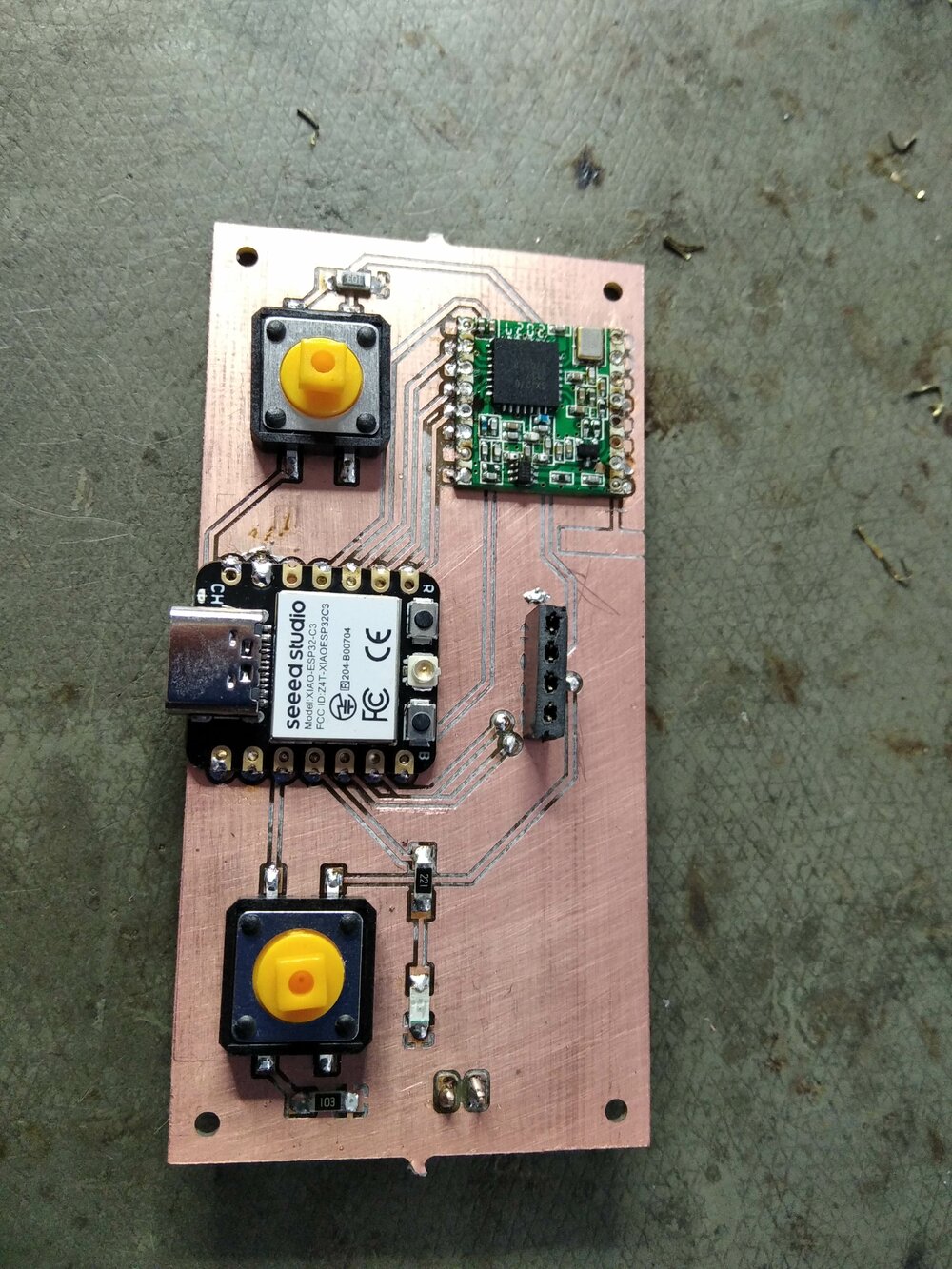
Finally, I resolder all the components in this new beautiful board.
Another video with the board solder?
Improvements
- Add some functions with the two buttons
- Add graphical screen
- Specific message to send to the board
- Use the LoRaWAN network
- Try to fix the XIAO ESP32C3 bug and connect with Bluetooth to a smartphone (Add GPS function?)
Files
Here are the files for the electronics part of Wally (code and board design/production).