Electronics
Graph
Before doing the Schematic in FreeCAD, I like to draw the graph with the link of all the components.
Board
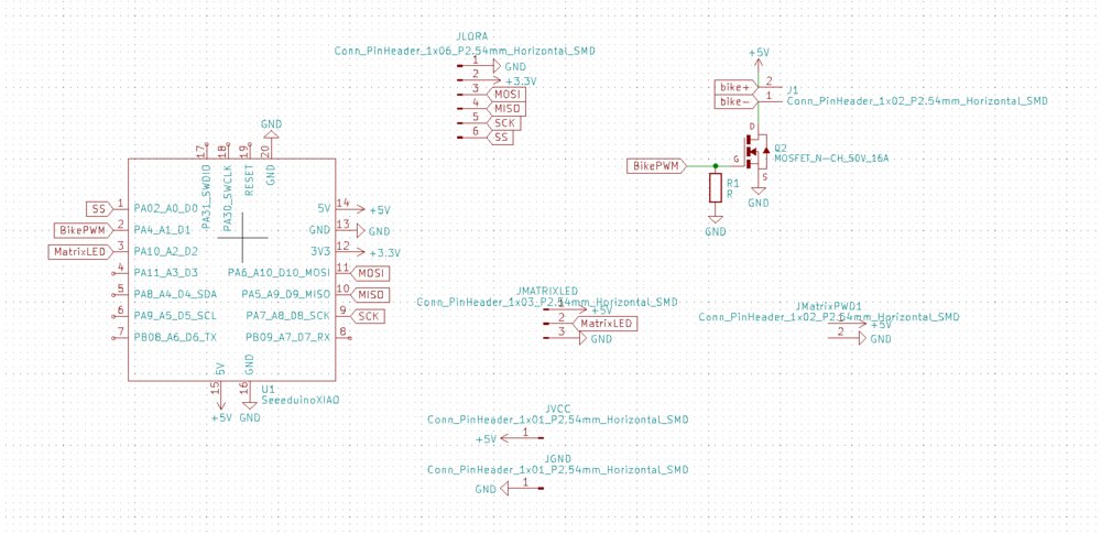
The board of the Sign is not too complex. I made a quick design of the board with the MCU (an XIAO SAMD21) and the pinout I had to expose. So there are the 4 pinouts for the SPI protocol + 3.3 and GND for the LoRa module. The is a digital pin to control a Mosfet to turn on and off the Bike LED and another one to command the Matrix LED.
I added also some pads to connect the power supply and to give more power to the Matrix LED.
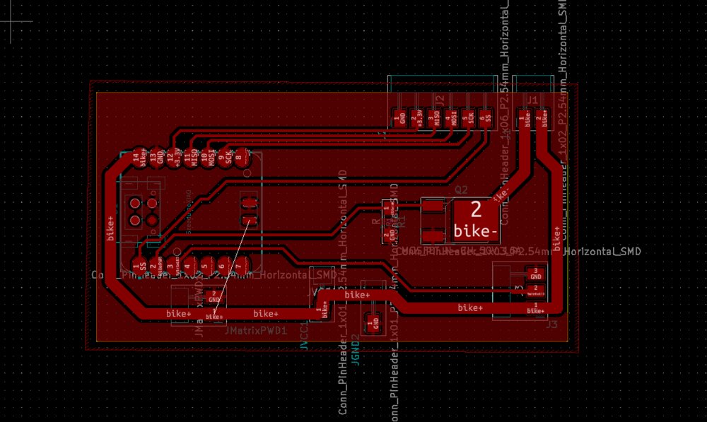
I wanted a single-layer PCB, so I made the tracks so I don't need vias. The LEDs (for the Bike and for the Matrix) can consume a lot of power. For security, I made thick tracks for the input 5v and the outputs that go to the LED. With this calculator, those tracks should be able to handle more than . For my use of the Matrix LED, it will be enough.

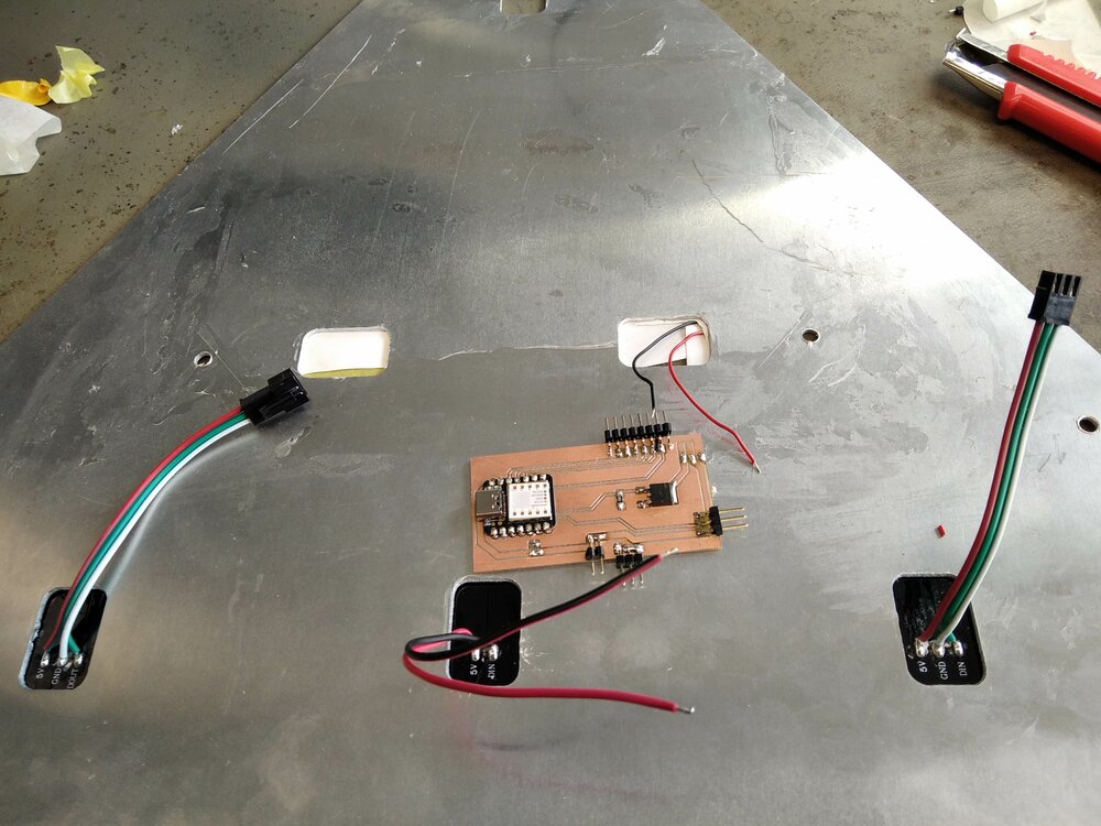
And here is the result. I solder 1 or two pinheads more so it's better attached to the board (Surface Mounted pinheads are weaker than Through Holes)
Bike LED
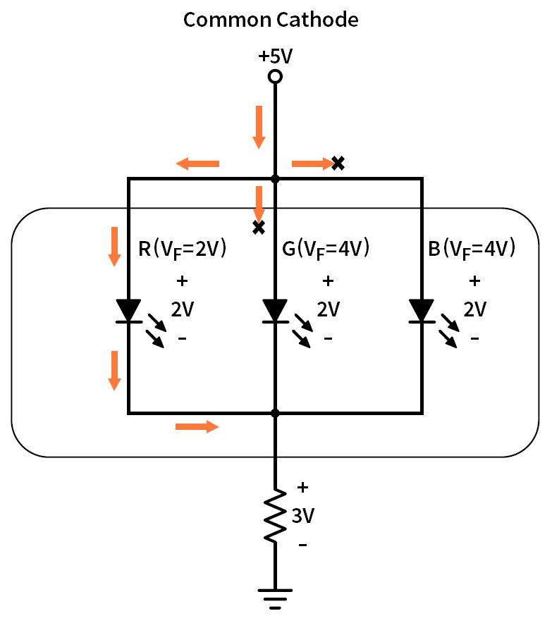
source circuitbread.com
After some readings, I discovered, that I can not share one resistor for an array of LED, so I'll have to pair resistors with each LEDs. One resistor for multiple LEDs in series is OK (and the order of it doesn't matter), but not in parallel.
So here is the schematic idea. To find the right values of the resistors, I used this formula:
1
Where is the forward voltage of my LED (~2V for my red LED) so I need a resistance of when there are two LEDs and a branch and when the LED is alone.
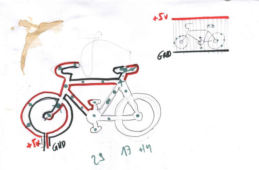
But how could the LEDs be placed in a bike shape? I draw an idea on an old piece of paper (with coffee on it). But I quickly realized that a "leds curtain" would be much easier to make (on the top right of the drawing).
 source lighthouseleds.com
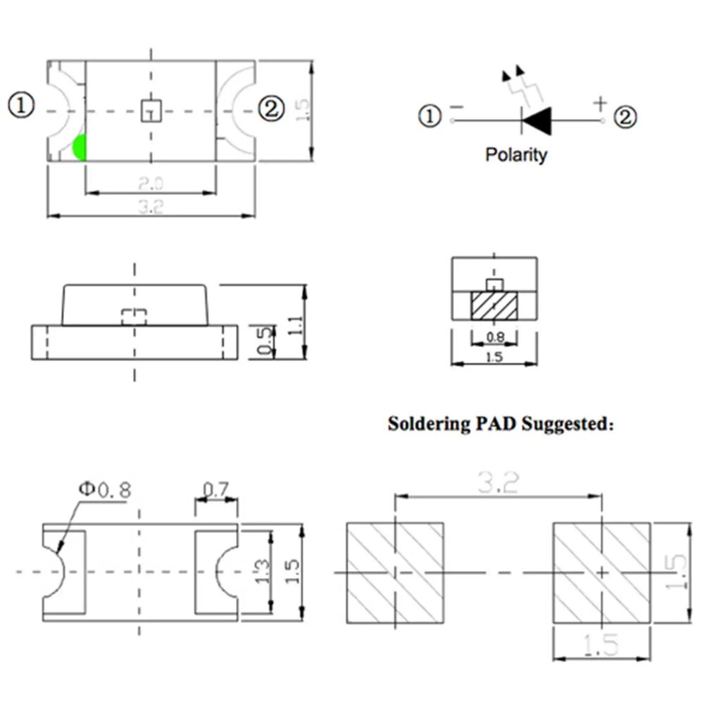
As it's a complex vectorial draw, I won't use KiCAD, but Fusion 360 instead. I just needed the footprint of my SMD LED and also the SMD 1206 electric resistances.
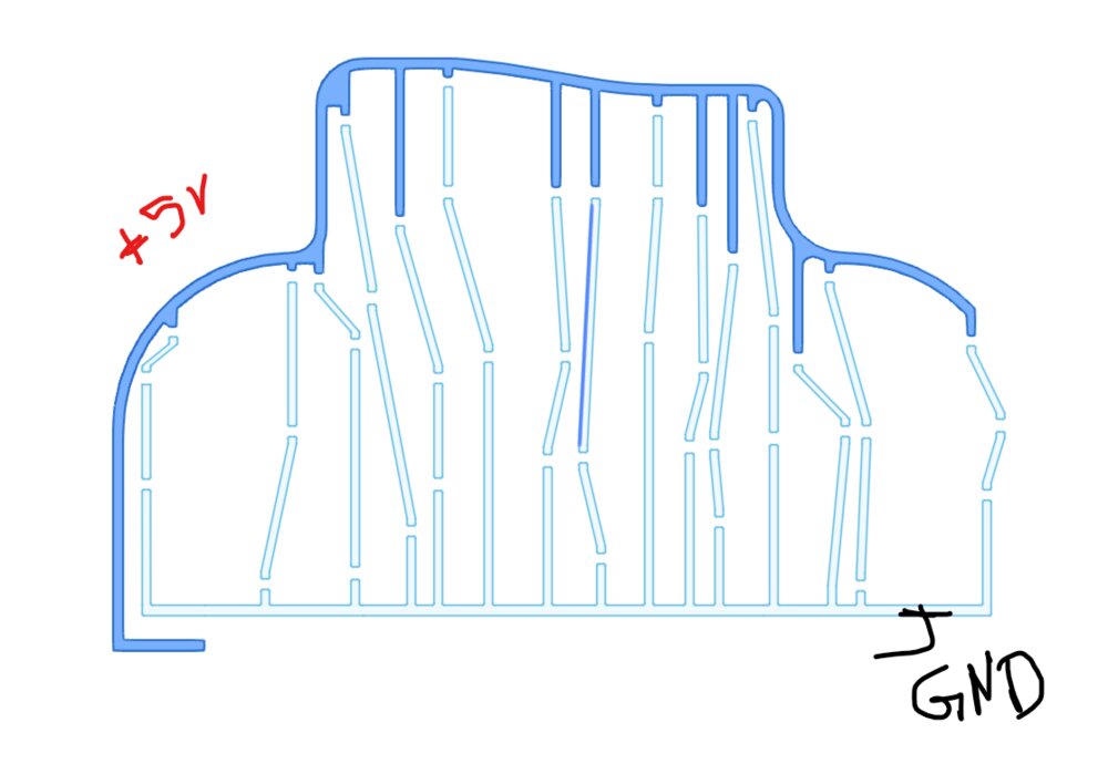
So with the bike in the background, I draw this. With my learnings from week15, I tried to draw the lines as straight as possible. It took me more than 4 hours to draw... an infinity! I should find a better way next time.
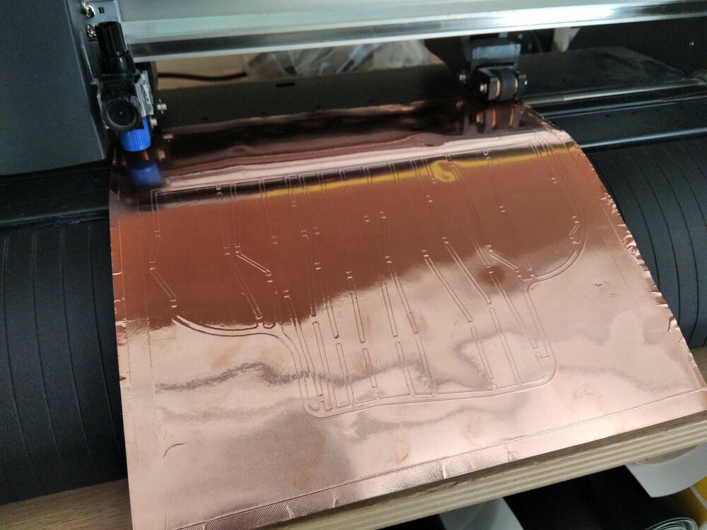
Using the parameters discovered in week15, I quickly launch the cut.
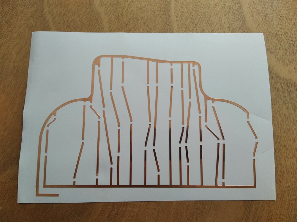
Here we go, I pealed off the tracks and put it on a reflective sheet of plastic (actually use for t-shirt transfer).
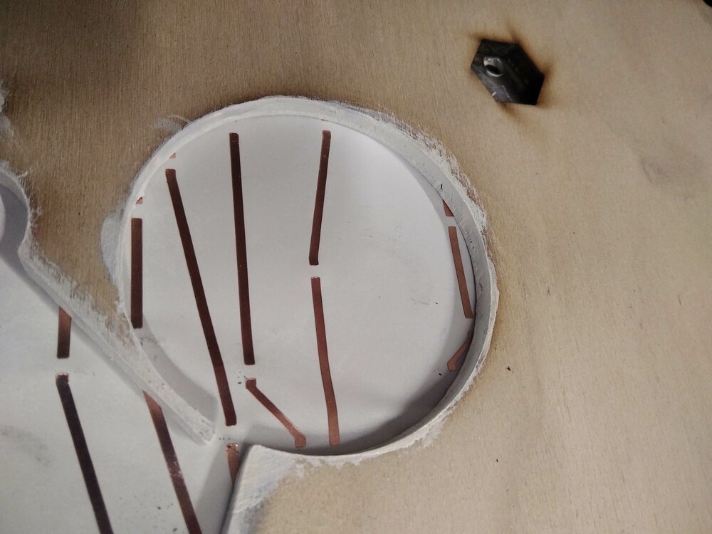
Damm... When I imported the DXF on the vinyl cut program, the software made a scale mistake, a small one, but now it doesn't fit in the frame. So I'll need to make another one.
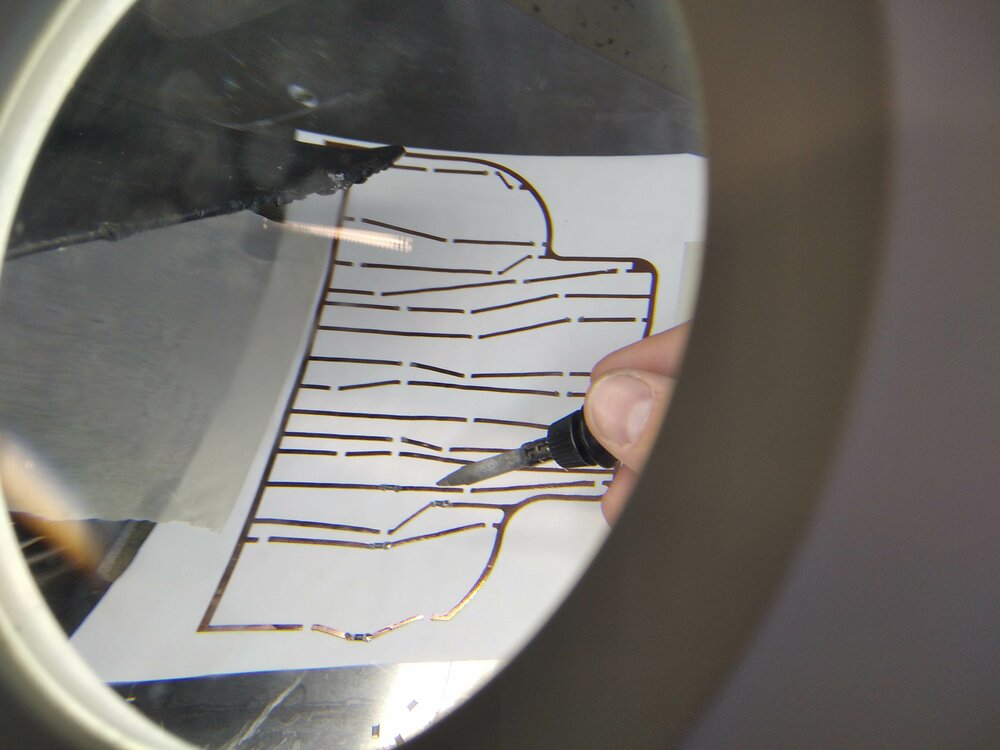
I then solder the LED with their resistances. I used solder paste, as the melting temperature is low to not burn the copper vinyl.
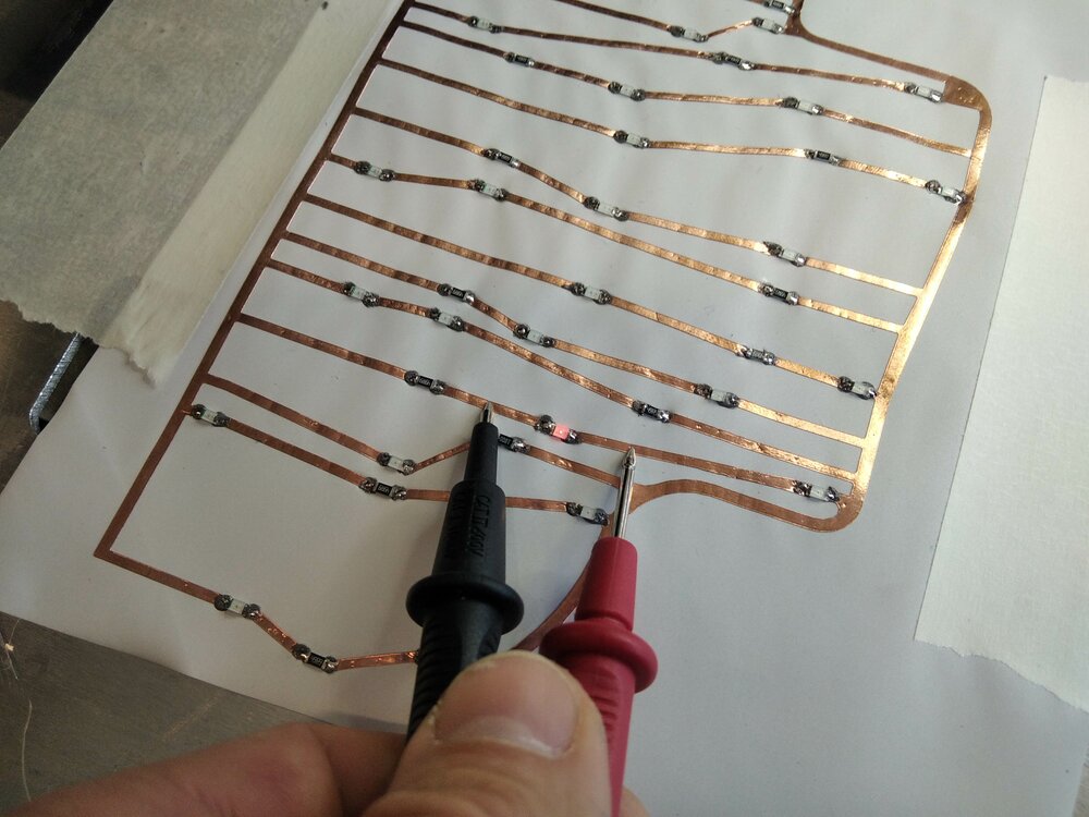
Then test the continuity along the way.
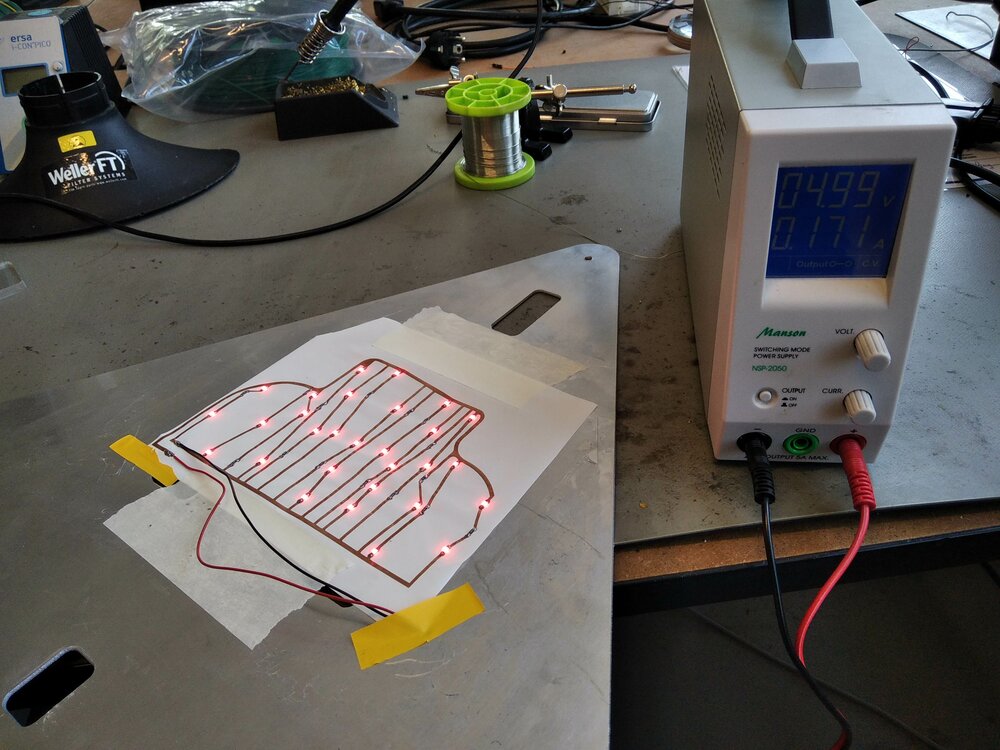
Tadaa, it's Christmas! And it actually doesn't draw as much current. Less than 200mA.
Code for the MCU
To be able to start to code before having all the parts, I looked for an Arduino Simulator. I didn't find one that was supporting my LoRa module, but Wokwi can simulate Matrix LED, pushbutton et OLED display, so I'll start with it.
Control the LED with an N-Mosfet.
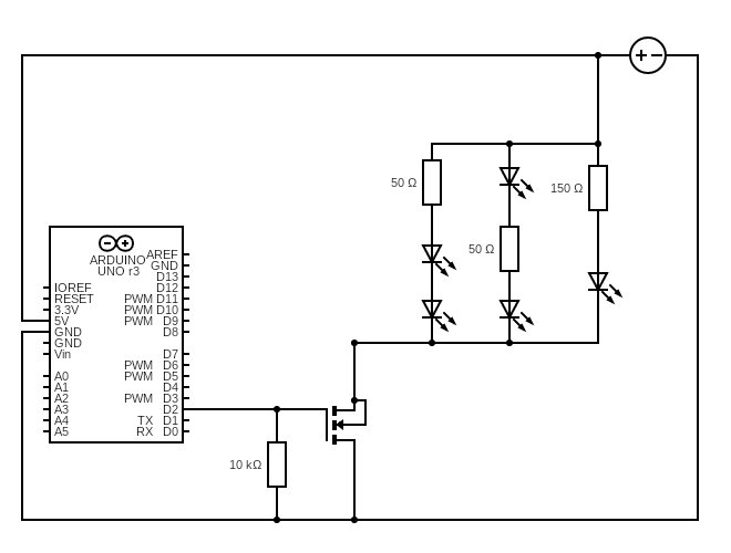
I have some IRF520N N-Mosfet. They can manage up to . As my LEDs need around 20mA, it means to I can put LEDs on the bike LEDs, it's more than enough.
schematics of the bike led
All we need is to connect the 5V to the LEDs and the "Ground" of the LED to the Drain of the Mosfet. The Gate will be connected to a pin of the board, and then the Source go to the actual Ground.
Here is a simple code to blink the LED.
#define PIN_BIKE 3 // Ouput of the Gate Mofet pin

void setup() {
  pinMode(PIN_BIKE, OUTPUT);
}

void loop() {
  digitalWrite(PIN_BIKE, HIGH);
  delay(500);
  digitalWrite(PIN_BIKE, LOW);
  delay(500);
}
Control de Matrix LED.
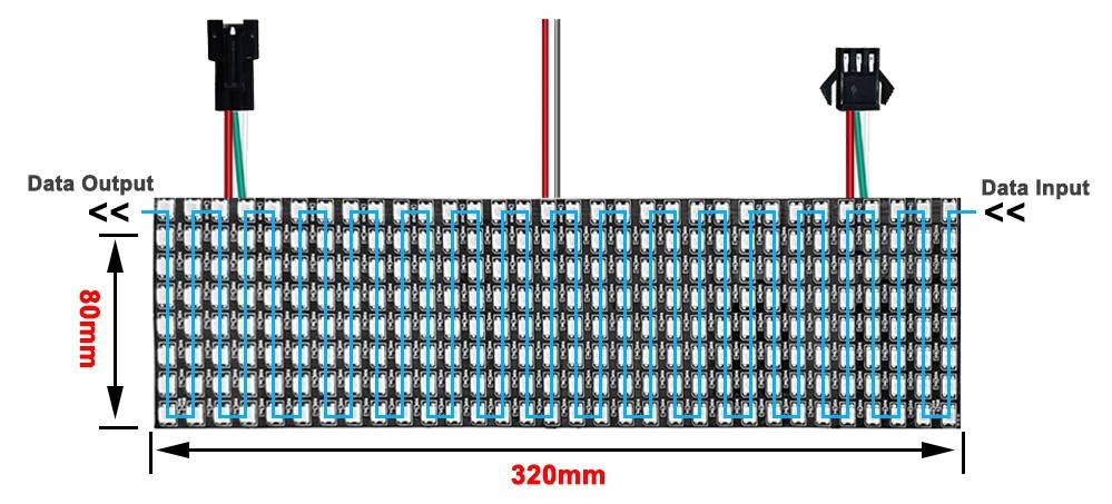
As explained in the frame section, the Traffic sign has 32 by 8 Matrix LEDs. Those 256 WS2812b RGB addressable LEDs are linked together in a Zigzag layout. But in the end, it's similar to an LED strip.
For that, Adafruit has created a nice library called NeoMatrix. This library needs the GFX and the NeoPixel library to work. One included, I first create an instance regarding my configuration.
#include <Adafruit_GFX.h>
#include <Adafruit_NeoPixel.h>
#include <Adafruit_NeoMatrix.h>

#define PIN 6 // Where the Matrix is connected on the board

Adafruit_NeoMatrix matrix = Adafruit_NeoMatrix(
    32,                  // Width of the Matrix in LED
    8,                   // Hieght of the Matrix  in LED
    PIN,                 // Data pin
    NEO_MATRIX_TOP +     // Top/Bottom location of the first LED
    NEO_MATRIX_RIGHT +   // Left/Right location of the first LED
    NEO_MATRIX_COLUMNS + // Arrangement vertical of LEDs
    NEO_MATRIX_ZIGZAG,   // Layout of the LEDs
    NEO_GRB +            // Pixels are wired for GRB bitstream
    NEO_KHZ800           // bitstream for WS2812 LEDs
);
Then I can set some parameters of the matrix object, like the color of the text or the brightness of the LEDs.
const uint16_t TextColor = matrix.Color(255, 0, 0); // Choose Red Color for

void setup() {
  matrix.begin();
  matrix.setTextWrap(false);
  matrix.setBrightness(100);
  matrix.setTextColor(TextColor);
}
I can now show some Hello World! =)
void loop() {
  printOnScreen("Hello");
  delay(500);
  printOnScreen("World");
  delay(500);
}

void printOnScreen(String msg) {
  matrix.fillScreen(0);
  matrix.setCursor(0, 0);
  matrix.print(msg);
  matrix.show();
}
No more Delay
Delays are cool, but they pause the program. So we can't listen to anything else (pushbutton, LoRa signal, etc.).If I choose the RP2040 board, as it has 2 cores, I could use one thread for the LED and the other one to listen to any Lora Signal.
But I preferred to look for a more versatile code using this tutorial.
So first I added some new variables before the setup.
int bikeState = LOW;  // bikeState used to set the LED
String warning[] = {"Bike", "on", "the", "Road"};
int arrayLength = 4;  // As there is not simple *length* function in cpp
int indexState = 0;

unsigned long previousMillis = 0;  // will store last time LED was updated


const long interval = 1000;  // interval at which to blink/switch words (milliseconds)
And here is the new loop:
void loop() {
  unsigned long currentMillis = millis();

  if (currentMillis - previousMillis >= interval) {
    previousMillis = currentMillis; // save the last time LED blinked
    printOnScreen(warning[indexState]); // print a word on the screen
    if (++indexState >= arrayLength) indexState = 0; //incremente the index
    digitalWrite(PIN_BIKE, bikeState); // set the LED with the correct state
    bikeState = !bikeState; // inverse the LED state for the next run
  }
}
Here is an example that says Bike in 100m.
Listen to LoRa
Now, that I don't pause my program anymore, I can listen to any LoRa message. For that, I'll use the Receiver part in my Network and communication week.
So first I need more library and set LoRa's configurations.
...
#include <SPI.h>
#include <LoRa.h>

...

#define SS 0 // where is the LoRa module connected

...

bool signOn = false;

int intervalsCount = O; // count the intervals
const int maxInterval = 60; // set how many intervals the sign will be on.

void setup() {
  ... // previous setup

  LoRa.setPins(SS);
  LoRa.begin(868E6) // Start LoRa with a frenquency of 868Mhz
}
Then I can watch for any Packet received by LoRa.
void loop() {
  // try to parse packet
  int packetSize = LoRa.parsePacket();
  if (packetSize) {
    // received a packet
    Serial.print("Received packet '");

    // Read the received data
    String receivedData = "";
    while (LoRa.available()) {
      char c = LoRa.read(); // Read a character from the packet
      receivedData += c; // Append the character to the string
    }
    If (receivedData == "bike") {
      signOn = true;
    }
  }
  ...
}
Once the string "bike" is received, I set the signOn = true, so I can reuse the LEDs code to light on the traffic sign for 60 intervals (= ).
void loop() {
  ...
  if (signOn) { // check is the Sign should be on

    unsigned long currentMillis = millis();

    if (currentMillis - previousMillis >= interval) {
      previousMillis = currentMillis; // save the last time LED blinked
      printOnScreen(warning[indexState]); // print a word on the screen
      if (++indexState >= arrayLength) indexState = 0; //incremente the index
      if(++intervalsCount >= maxInterval) { // the max Interval is reached the Sign is turn off and all the variable reset the their original values.
        signOn = false;
        previousMillis = 0;
        bikeState = HIGH;
        indexState = 0;
        digitalWrite(PIN_BIKE, bikeState); // set the LED with the correct state
      } else {
        digitalWrite(PIN_BIKE, bikeState); // set the LED with the correct state
        bikeState = !bikeState; // inverse the LED state for the next run
      }
    }
  }
}
Let's put this together
The intermediate layer in aluminum gets all the electronics. There are holes for wires to pass through.
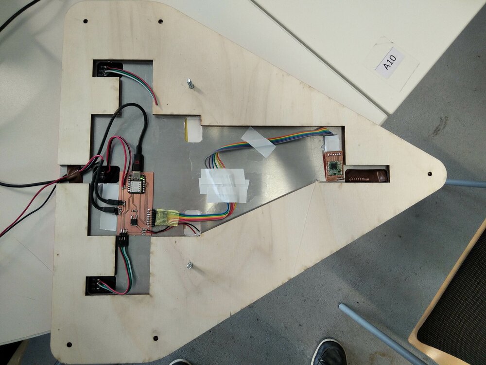
For the penultimate layer in wood, it let me arrange a bit the cables.
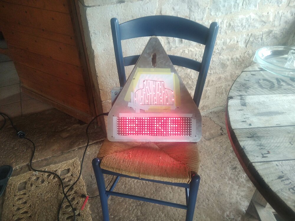
So let's do a simple "LED light on" test. It's working!
So let's finish the assembly and I can work on the Wally LoRa module.
Files
Here are the files I used to make the Bike LED PCB and the Board and the code.
- PCB_vinyl.f3d
- pcb_bike.dxf
- sign_board.ino
- traffic_sign_board.kicad_pro
- traffic_sign_board.kicad_pcb
- traffic_sign_board.kicad_sch
- traffic_sign_board-PTH.drl
- traffic_sign_board.kicad_prl
- traffic_sign_board-B_Cu.gbr
- traffic_sign_board-Edge_Cuts.gbr
- traffic_sign_board-F_Cu.gbr
- traffic_sign_board-job.gbrjob
- traffic_sign_board-NPTH.drl