Input devices
Measure something: add a sensor to a microcontroller board
that you have designed and read it
Group assignment:
Group Assignment
For this GA Ahmed showed me how to probe an HC-SR04 and a potentiometer using an oscilloscope.
Let's start with the potentiometer:
First, upload this example AnalogInOutSerial code to your board:
							/*
  Analog input, analog output, serial output

  Reads an analog input pin, maps the result to a range from 0 to 255 and uses
  the result to set the pulse width modulation (PWM) of an output pin.
  Also prints the results to the Serial Monitor.

  The circuit:
  - potentiometer connected to analog pin 0.
    Center pin of the potentiometer goes to the analog pin.
    side pins of the potentiometer go to +5V and ground
  - LED connected from digital pin 9 to ground

  created 29 Dec. 2008
  modified 9 Apr 2012
  by Tom Igoe

  This example code is in the public domain.

  http://www.arduino.cc/en/Tutorial/AnalogInOutSerial
*/

// These constants won't change. They're used to give names to the pins used:
const int analogInPin = A0;  // Analog input pin that the potentiometer is attached to
const int analogOutPin = 9; // Analog output pin that the LED is attached to

int sensorValue = 0;        // value read from the pot
int outputValue = 0;        // value output to the PWM (analog out)

void setup() {
  // initialize serial communications at 9600 bps:
  Serial.begin(9600);
}

void loop() {
  // read the analog in value:
  sensorValue = analogRead(analogInPin);
  // map it to the range of the analog out:
  outputValue = map(sensorValue, 0, 1023, 0, 255);
  // change the analog out value:
  analogWrite(analogOutPin, outputValue);

  // print the results to the Serial Monitor:
  Serial.print("sensor = ");
  Serial.print(sensorValue);
  Serial.print("\t output = ");
  Serial.println(outputValue);

  // wait 2 milliseconds before the next loop for the analog-to-digital
  // converter to settle after the last reading:
  delay(2);
}
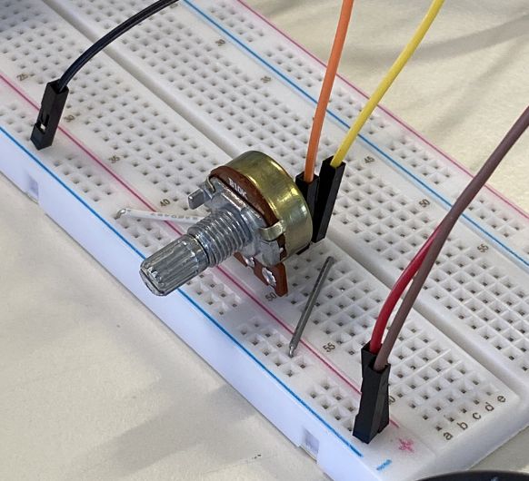 Connection of the potentiometer: VCC and GND plus the SIG pin in the
middle. The yellow cable goes to my board and the orange cable goes to the
oscilloscope.
Connection of the potentiometer: VCC and GND plus the SIG pin in the
middle. The yellow cable goes to my board and the orange cable goes to the
oscilloscope.
Moving onto the HC-SR04. First upload the following code to your board. It will initialize the sensor and output the duration with the according distance on the serial monitor.
int trigPin = 6;    // Trigger
int echoPin = 7;    // Echo
long duration, cm, inches;

void setup() {
  //Serial Port begin
  Serial.begin (9600);
  //Define inputs and outputs
  pinMode(trigPin, OUTPUT);
  pinMode(echoPin, INPUT);
}

void loop() {
  // The sensor is triggered by a HIGH pulse of 10 or more microseconds.
  // Give a short LOW pulse beforehand to ensure a clean HIGH pulse:
  digitalWrite(trigPin, LOW);
  delayMicroseconds(5);
  digitalWrite(trigPin, HIGH);
  delayMicroseconds(10);
  digitalWrite(trigPin, LOW);

  // Read the signal from the sensor: HIGH pulse (duration of the time (in microseconds)
  // from sending of the ping to reception of its echo off of an object.)
  pinMode(echoPin, INPUT);
  duration = pulseIn(echoPin, HIGH);//Reads a pulse (either HIGH or LOW) on a pin.
          //For example, if value is HIGH, pulseIn() waits
          //for the pin to go from LOW to HIGH, starts timing,
          //then waits for the pin to go LOW and stops timing.

  // Convert the time into a distance
  cm = (duration/2) / 29.1;     // Divide by 29.1 or multiply by 0.0343 (The speed of sound is: 343m/s = 0.0343 cm/uS = 1/29.1 cm/uS)


  Serial.print(duration);
  Serial.print("duration, ");
  Serial.print(cm);
  Serial.print("cm");
  Serial.println();

  delay(250);
}
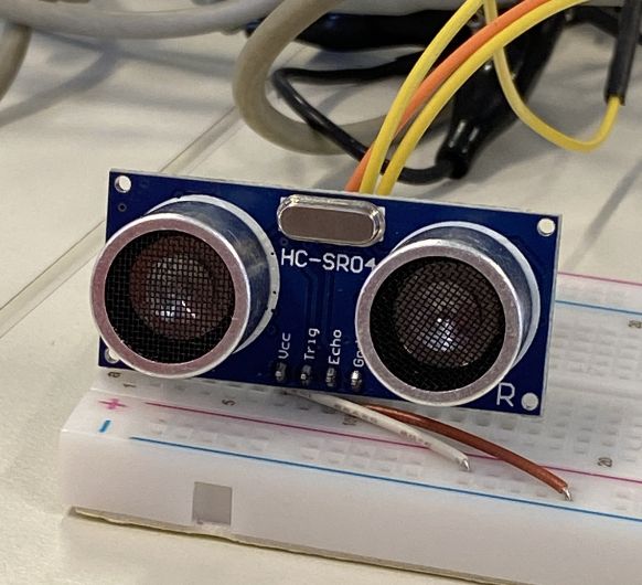 Connection of the HC-SR04 with my board. VCC and GND. Echo is the
yellow cable and Trigger is the orange cable. They are connected to pin 7 and 6 on
my board. The yellow echo is also connected to the oscilloscope. We'll be measuring
it's signals in the following.
Connection of the HC-SR04 with my board. VCC and GND. Echo is the
yellow cable and Trigger is the orange cable. They are connected to pin 7 and 6 on
my board. The yellow echo is also connected to the oscilloscope. We'll be measuring
it's signals in the following.
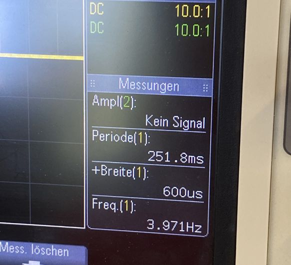 We are measuring the frequency and the width.
Design and fabrication of the PCB
You can see the documentation for this on my previous weeks' pages: Electronics design & Electronics production
Writing the program
It makes sense to program the microcontroller before connecting other devices, since they might
interfere with the upload connection for the code.
The program shown below combines my two codes from Embedded
programming / Output devices
It defines the pin connected to the
MOSFET's Gate as an output pin as well as all the pins for the HC-SR04 (the input device of this
assignment). Everytime the HC-SR04 senses a distance of less than 4cm the pump will activate.
The pump gets activated by power that is supplied to the pin, which bridges the connection
between
the Drain and the Source of the MOSFET, connecting the GND of the pump to the common GND and
therefore enabling it to run:
(This code was written with the help of ChatGPT and Rui
Santos, https://randomnerdtutorials.com and modified by me.)
int trigPin = 8;    // Trigger
int echoPin = 7;    // Echo
long duration, cm, inches;
int pumpPin = 9;    // MOSFET Pin for pump control
int minDistance = 4; // Minimum distance for pump activation in cm

void setup() {
	//Serial Port begin
	Serial.begin (9600);
	//Define inputs and outputs
	pinMode(trigPin, OUTPUT);
	pinMode(echoPin, INPUT);
	pinMode(pumpPin, OUTPUT); // Set pumpPin as an output
}

void loop() {
	// The sensor is triggered by a HIGH pulse of 10 or more microseconds.
	// Give a short LOW pulse beforehand to ensure a clean HIGH pulse:
	digitalWrite(trigPin, LOW);
	delayMicroseconds(5);
	digitalWrite(trigPin, HIGH);
	delayMicroseconds(10);
	digitalWrite(trigPin, LOW);

	// Read the signal from the sensor: HIGH pulse (duration of the time (in microseconds)
	// from sending of the ping to reception of its echo off of an object.)
	pinMode(echoPin, INPUT);
	duration = pulseIn(echoPin, HIGH);//Reads a pulse (either HIGH or LOW) on a pin.
			//For example, if value is HIGH, pulseIn() waits
			//for the pin to go from LOW to HIGH, starts timing,
			//then waits for the pin to go LOW and stops timing.

	// Convert the time into a distance
	cm = (duration/2) / 29.1;     // Divide by 29.1 or multiply by 0.0343
	inches = (duration/2) / 74;   // Divide by 74 or multiply by 0.0135

	Serial.print(inches);
	Serial.print("in, ");
	Serial.print(cm);
	Serial.print("cm");
	Serial.println();

	// Activate pump if distance is less than minDistance
	if (cm < minDistance) {
	digitalWrite(pumpPin, HIGH); // Turn on the pump
	} else {
	digitalWrite(pumpPin, LOW); // Turn off the pump
	}

	delay(250);
}Connections of the input + output device
Components mentioned:
- 5V regulator LM7805 (Input Voltage: Minimum 7V, Maximum 25V Output Current: 1.5A)
- 12V power adapter
- 12V peristaltic pump
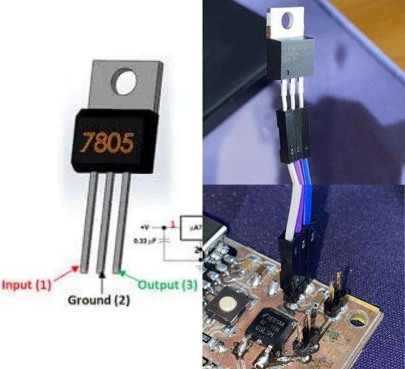 Connect the 5V regulator to the pin header. Mind the right orientation.
Input to 12V side, Ground to GND, Output to 5V side ->
You can check this in a datasheet or test it on a breaboar with a multimeter.
Connect the 5V regulator to the pin header. Mind the right orientation.
Input to 12V side, Ground to GND, Output to 5V side ->
You can check this in a datasheet or test it on a breaboar with a multimeter.
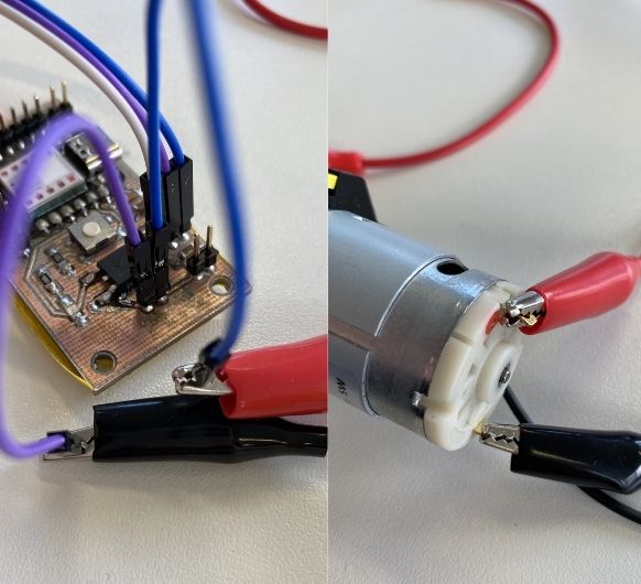 Connect the pump: VCC to 12V and GND to common GND
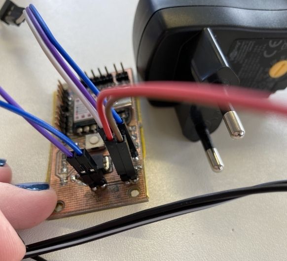 Connect the power adapter
(don't connect it to a power outlet yet): VCC
to VCC and GND to GND.
Connect the power adapter
(don't connect it to a power outlet yet): VCC
to VCC and GND to GND.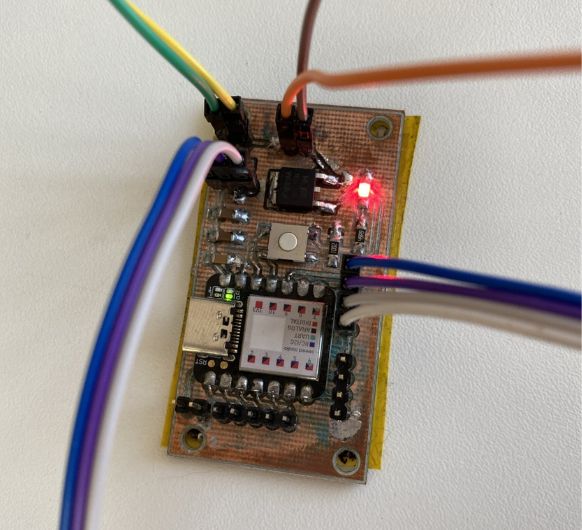 Connect the HC-SR04 to
the corresponding pins.
Connect the HC-SR04 to
the corresponding pins.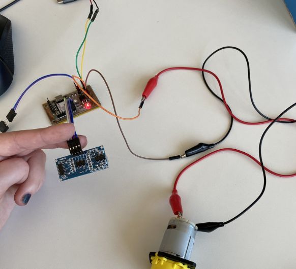 Overview:
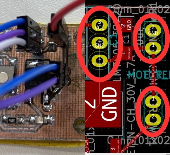 Make sure everything
is correctly connected. Check your KiCad design to
make sure.
Make sure everything
is correctly connected. Check your KiCad design to
make sure.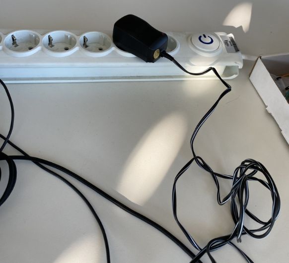 Now connect the power
adapter to a power outlet.
Now connect the power
adapter to a power outlet.