MACHINE BULDING
We are a Team of creative people passionate about Fabrication Laboratories, that like to explore new ideas and challengings.
Barth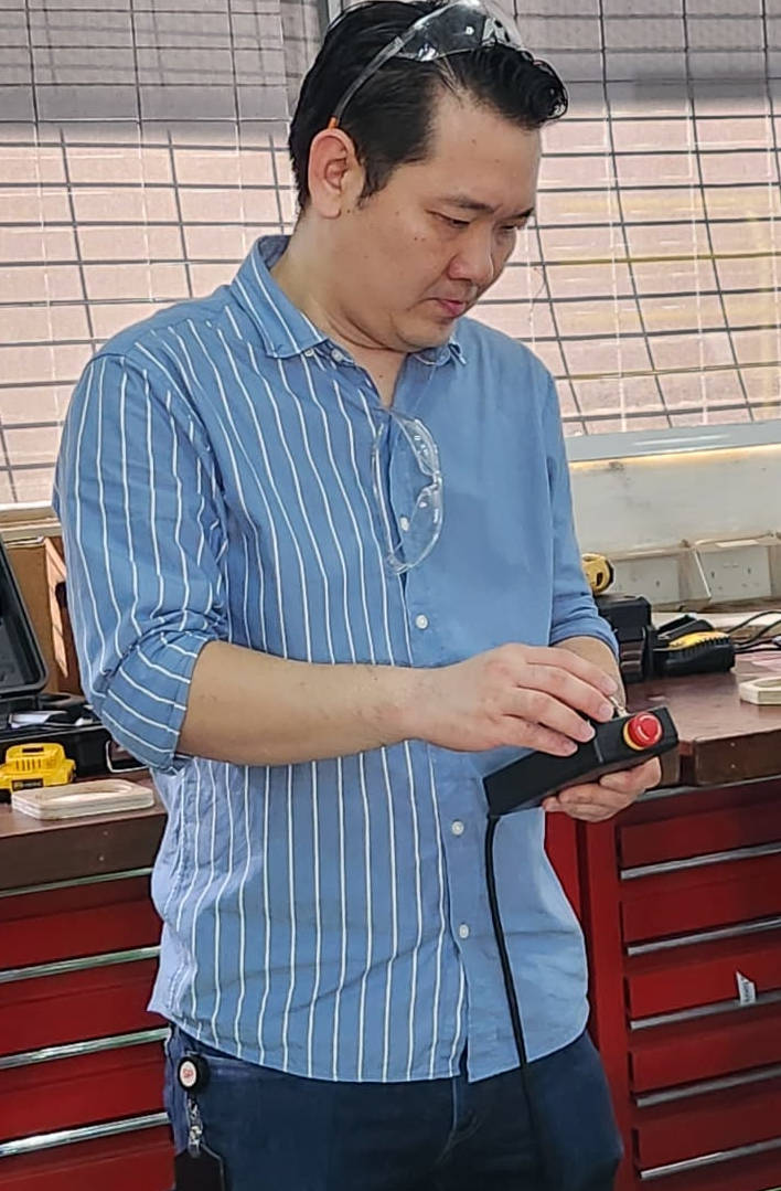
|
Juliana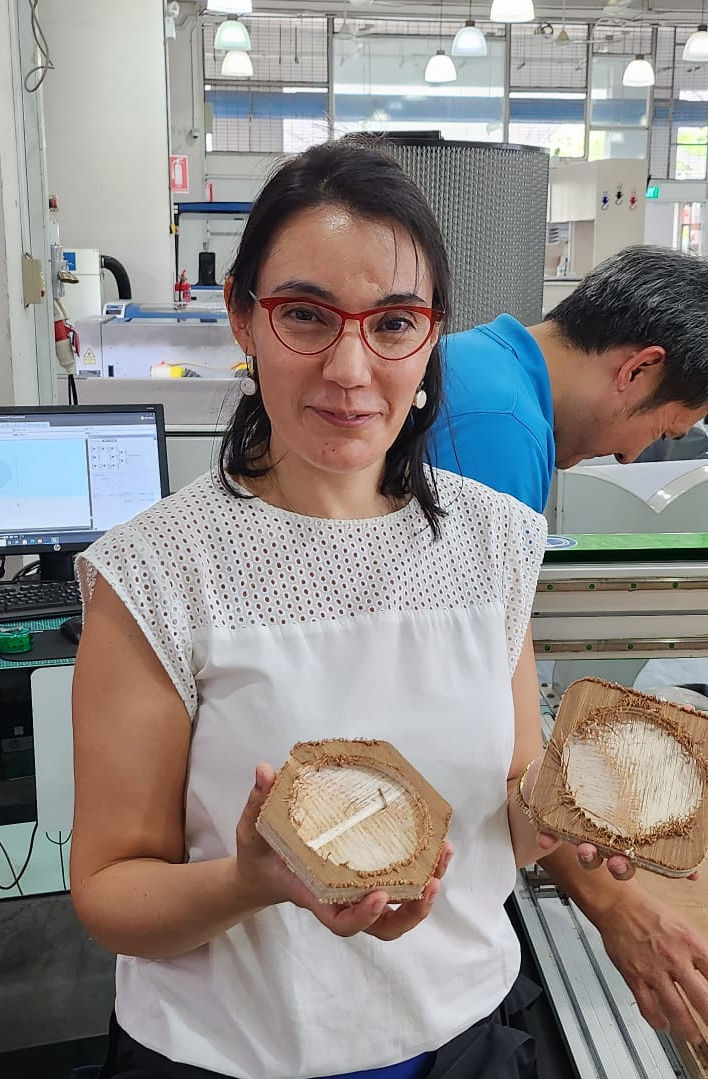
|
Seh Yong
|
Willie
|
MACHINE: “XY WALL PLOTTER ROBOT”
Our team has decided to built an "XY Wall Plotter Robot" that utilizes G-Code software to control the robot's drawing of images. We drew inspiration from another CREATOR on the internet and eagerly took on the challenge of constructing this machine.
Throughout the project, we faced various unique challenges, such as designing the machine, 3D printing the parts, working with electronics, and programming the software to set the Robot functions and generate the images.
One of our key goals was to make the parts easily disassembled and compacted, which led us to design the parts in 3D. The size of the drawing area can be changed relocating the motors in different positions that are set at the Plotter base structure. This approach allowed us to create a more versitile and practical machine.
HERO IMAGES AND VIDEOS
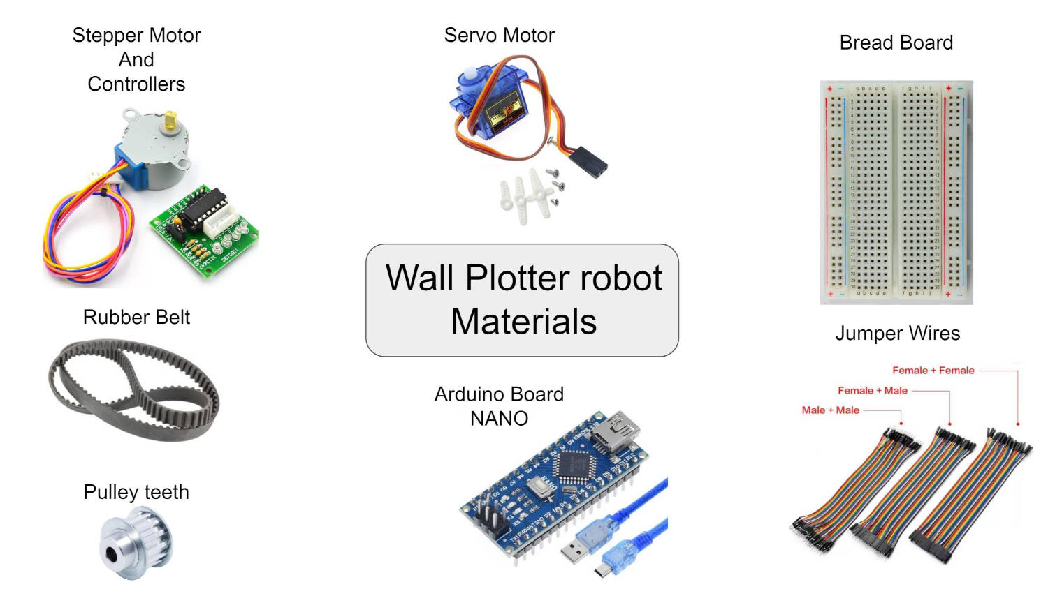
MATERIALS
- 5V Stepper Motor 28BYJ-48 + ULN2003 Driver (2 pieces)
- Servo Motor FS90
- Pulley teeth set (2 pieces)
- Rubber belt, 3.0mt length approx.
- Bench Power supply (5V)
- Weights, we used metal bearing gears.
- Jumper wires to connect the board to the Gondola
- Arduino Uno for the machine test
- 3D printed parts
PCB
- Arduino Board Nano
- Pin CB connectors
- Switch ON-OFF button
- Plug for Power Adaptor
WORKFLOW
We tackled the project head-on by breaking it down into several fronts, and by strategically dividing the workload, but as a team, we collaborated to perform preliminary tests on the machine, establish connections, and troubleshoot any issues that arose during the setup process. Here's how we did it:
- Setting Up: Connecting the motors to an Arduino Uno Microcontroller, using bread Board connections and running simple programs to move the motors
, as this was our first time working with them. (Barth and Seh Yong) - Codes:Dowloading the Codes to control the "XY Wall Plotter Robot", to set the motors and operate the robot. (Barth and Seh Yong)
- Software:Operating the Software to send the images to the Plotter to draw. (Barth)
- 3D Printing: Design and print Robot parts. (Willie)
- ElectronicsCable management and PCB design and production to organize and arranging all the cables in a way that makes them easier to handle and keep tidy. (Juliana)
- Group Web Page: Collect all the information from the ream members and added it to the group's webpage. (Juliana)
- Video: Time lipse video of the machine qorking. (Barth)
1. SETTING UP
As we have never worked with Stepper motors we did a “quick” installation of the motors to test the library code
We used the bread board to do this connections faster, and left to a later stage the board connection and cable management of the final product.
When it comes to basic movements, we can rely on the power supply from the computer. However, for a more dependable power source of 5 volts, later when putting the machine together, we opted to connect the machine to a Bench Power supply. This was especially necessary since the motors we were using consumed a significant amount of current.
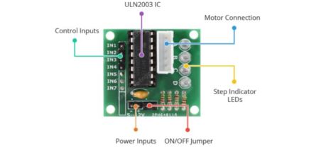
To properly manage this high current consumption and the comunication with the board, we needed to connect the motors to a Motor Driver ULN2003. The Motor Driver works by taking the low current control signal that comes from the Microcontroller and amplifying it into a higher signal that can effectively drive the motors.
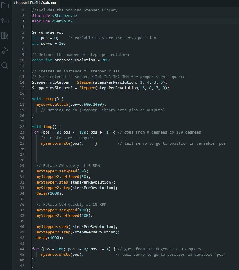
2.CODES
For the code of the software, we downloaded it from the github page of mXY-board-xy-plotter-drawing-machine
There are two source codes: one for Arduino and one for Processing. Since the codes are downloaded, we spent sometime going through the code to make sure we understand the code as much as possible.
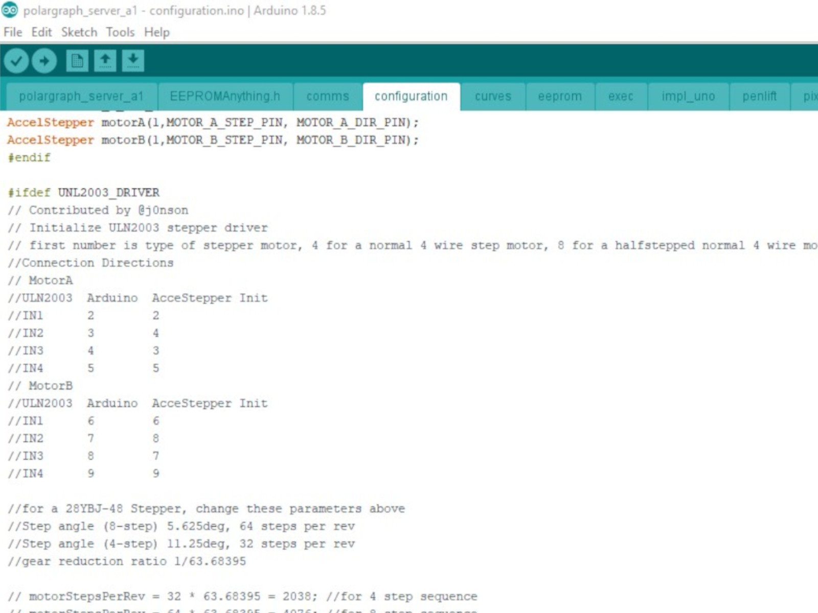
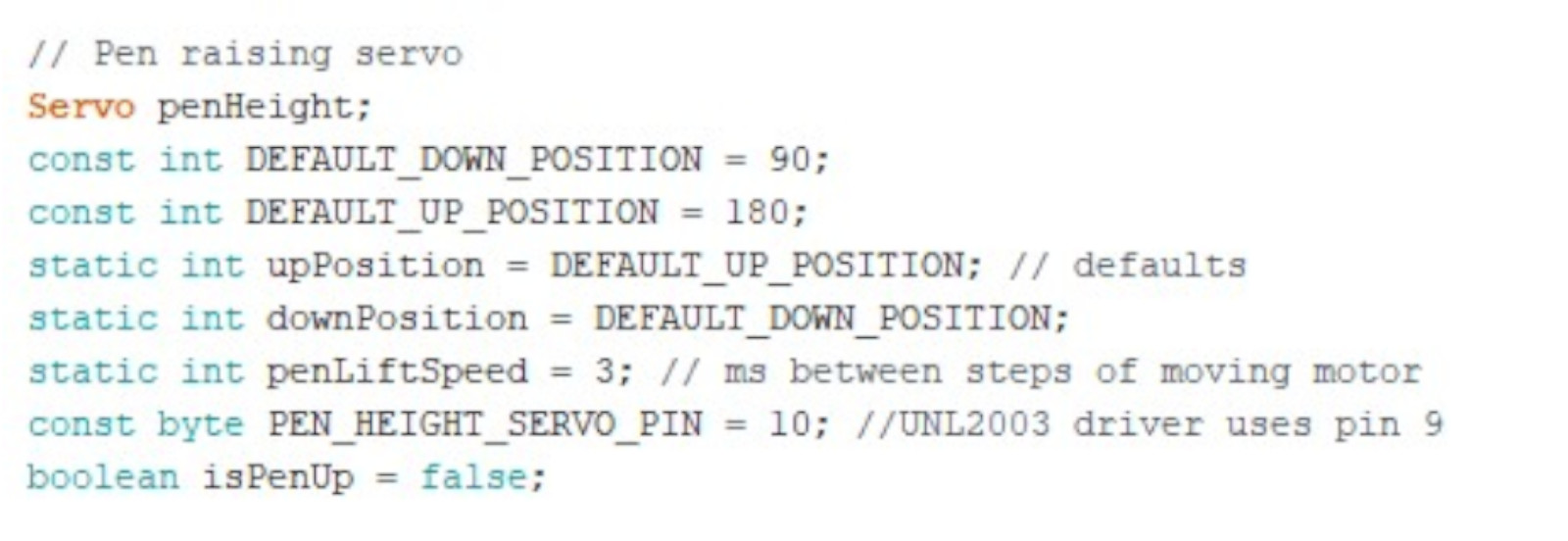
The arduino source code is for controlling the output devices (i.e. the stepper motors and the servo motors).
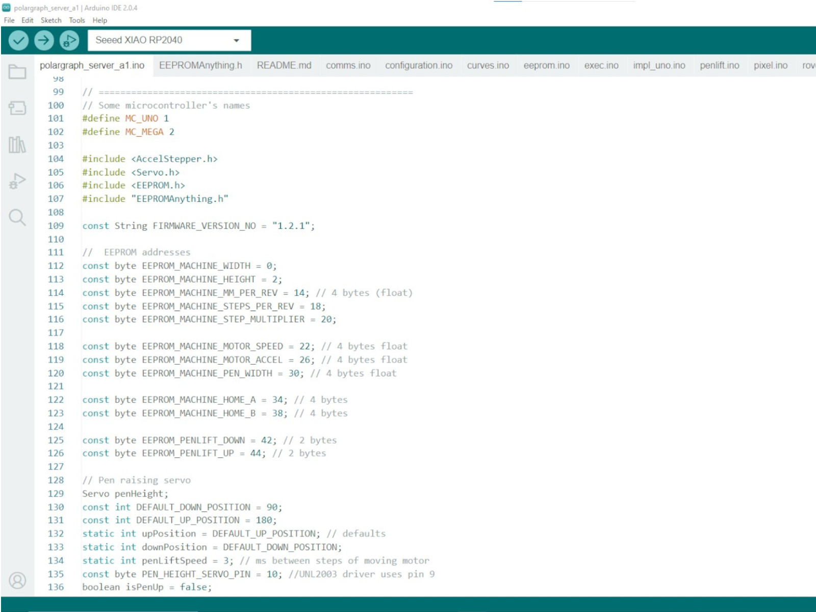
From the arduino source code, we found out the pins to connect to the stepper motors and servo motors.
On the other hand, the Processing source code is for launching an interface to input the image to be drawn, as well as adjusting the settings of the machine. The instructions on how to draw the image is also generated here and sent to the arduino board.
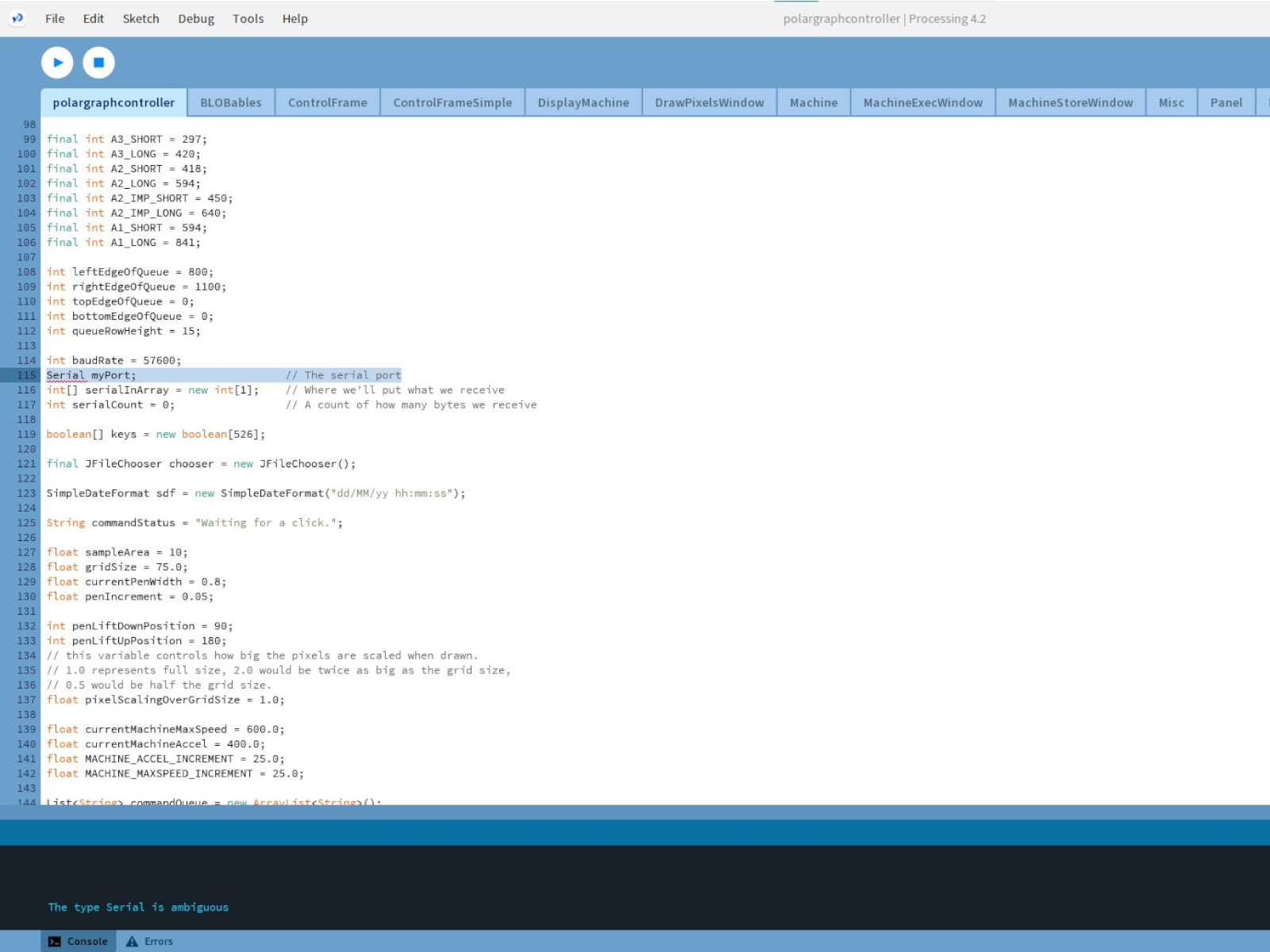
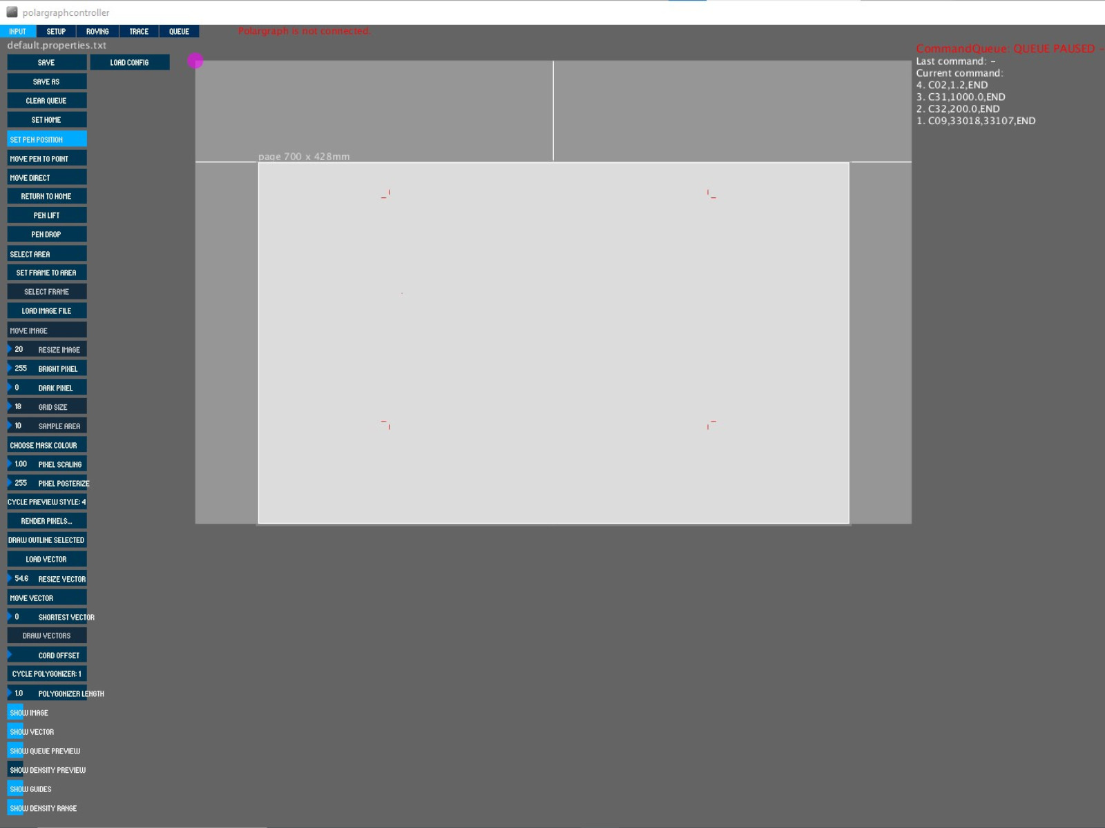
We encountered an "The type Serial is ambiguous." error with the processing soure code when we tried to run it in the lastest version of Processing (version 4.2). We then followed the instruction in Github page of the drawing machine and used the earlier version of Processing v2.2.1 instead. Using this version, we were able to launch the interface:
For good measures, we also used Arduino IDE v1.8.5 to upload the Arduino source code into the Arduino board. The upload was completed without issue.
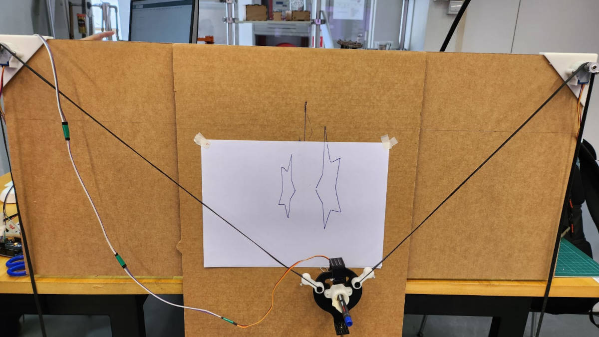
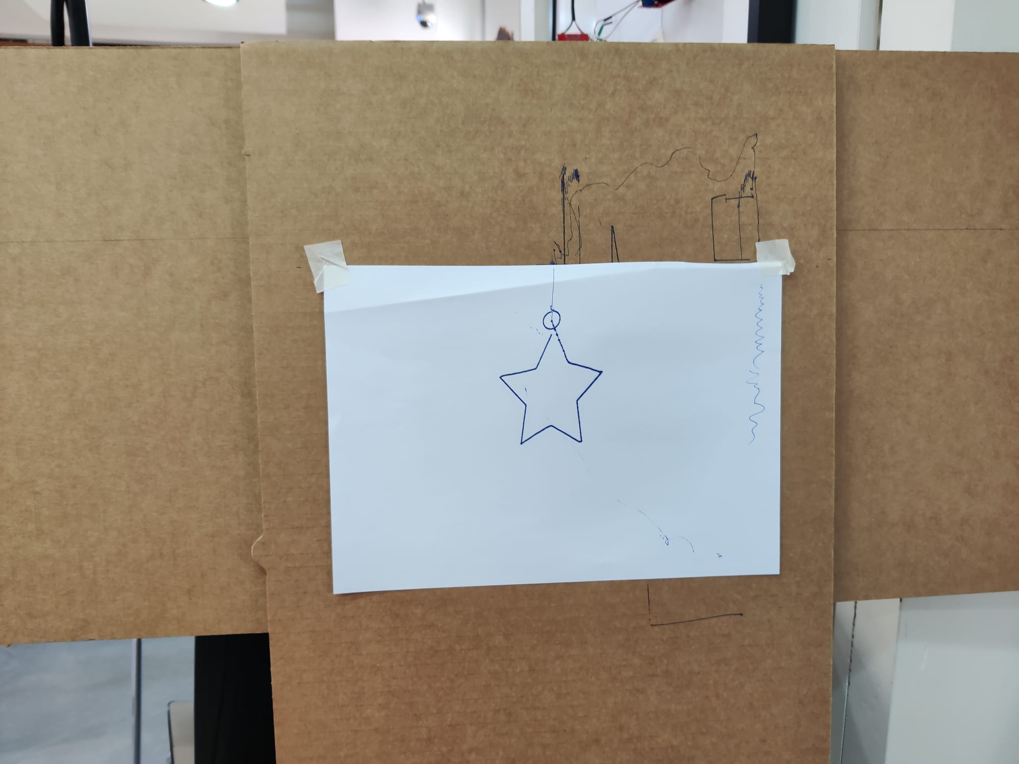
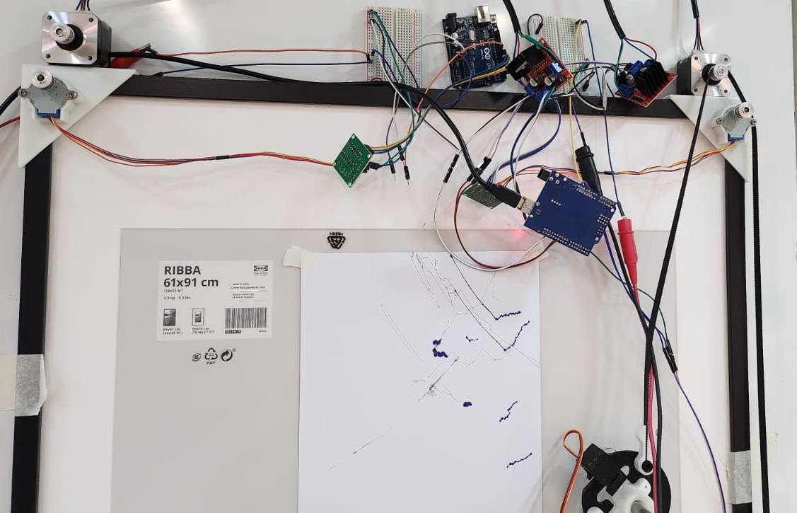
After we assembled our machine, we tested it by drawing a star-shaped pattern and found that the movement of the gondola was inverted in both X and Y axes. We then did an investigation to determine what were the issues.
We were able to narrow down the possible cause of the inversion to the motors being wired wrongly. To investigate further, we then tried to control the gondola to move downwards. When we did that, we found that the Gondola moved to the right instead. By observing the movement of the motors, we determined the left motor was not moving as expected (i.e. it should be rotating clockwise, but instead it was rotating anti-clockwise)
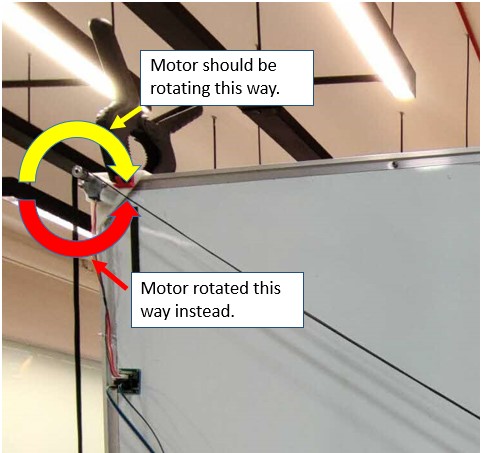
To resolve this issue, we "flipped" the connection from the Arduino board to motor driver and tested the downwards movement again. This time the gondola moved as expected.
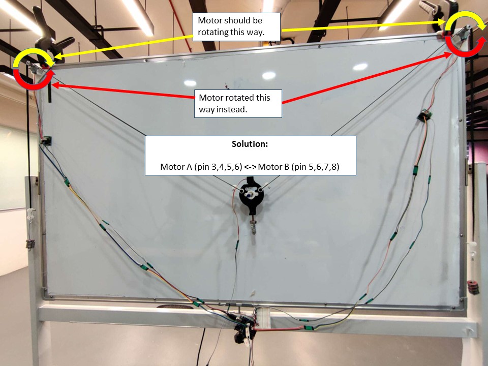
Afterward, we tried controlling the gondola to move to the right, but it moved to the left instead. We then "swapped" the connection of the motor drivers to the Arduino board. We tested the movement again and the Gondola moved to the sides as expected.
Finally, we tested the plotter by drawing the star-shaped pattern again. This time we were able to get the desired result.
3.SOFTWARE
4.MODELING AND 3D PRINTING
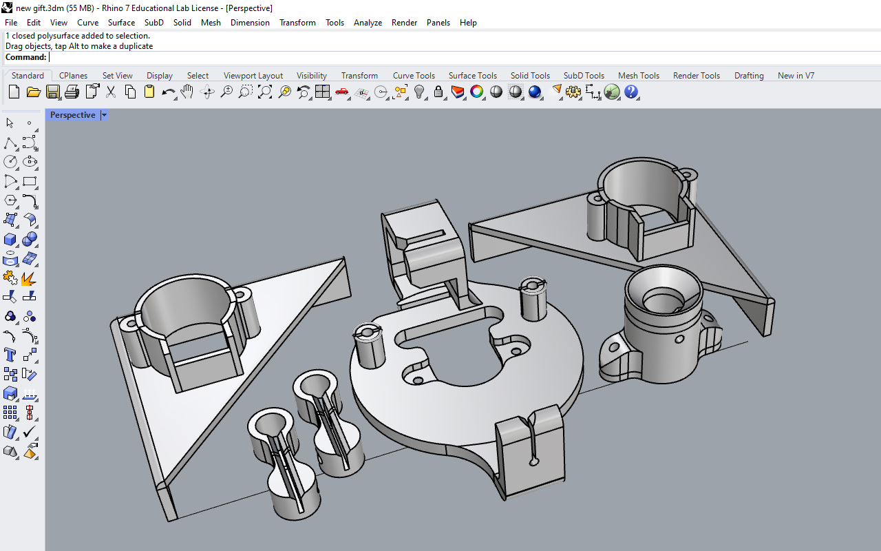
Willie started off designing the XY plotter drawing robot with references from similar projects and then made some modifications to the standard design that usually comes with a Gondola Pen Holder and 2 units of Stepper Motor Brackets. Below is a screenshot of the first prototype sample of the XY plotter drawing robot done in Rhino3D.
We then did a test on the XY plotter drawing robot and after a series of trial and error as well as troubleshooting, we finally manage to get it work and draw. Once we were sure that our XY plotter drawing robot was working, willie then further refined and modified our drawing robot design.
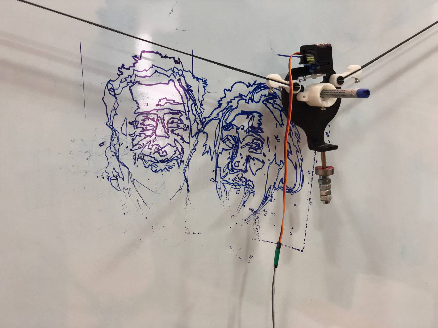
he first modifications starts with the Gondola itself as we were thinking of making it modular and universal in the sense that it can accommodate differ types of pens and markers of various diameters. Therefore, in order to achieve this, we actually separated the pen holder part from the Gondola so we coul fit a different pen or marker holder by press-fitting.
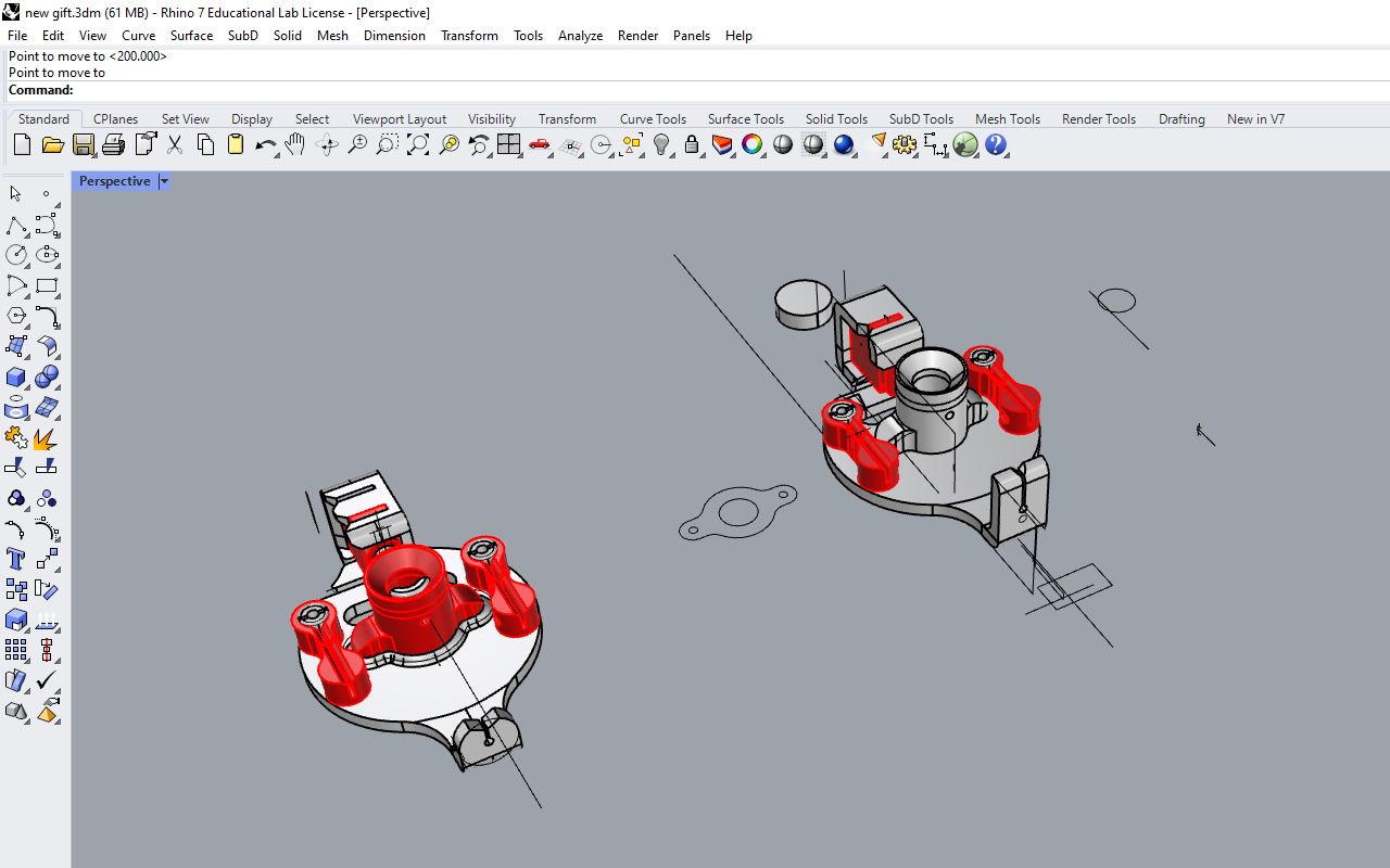
Below show some images of the final design of the XY plotter drawing robot done in Rhino3D CAD and then being 3D printed and laser cut.
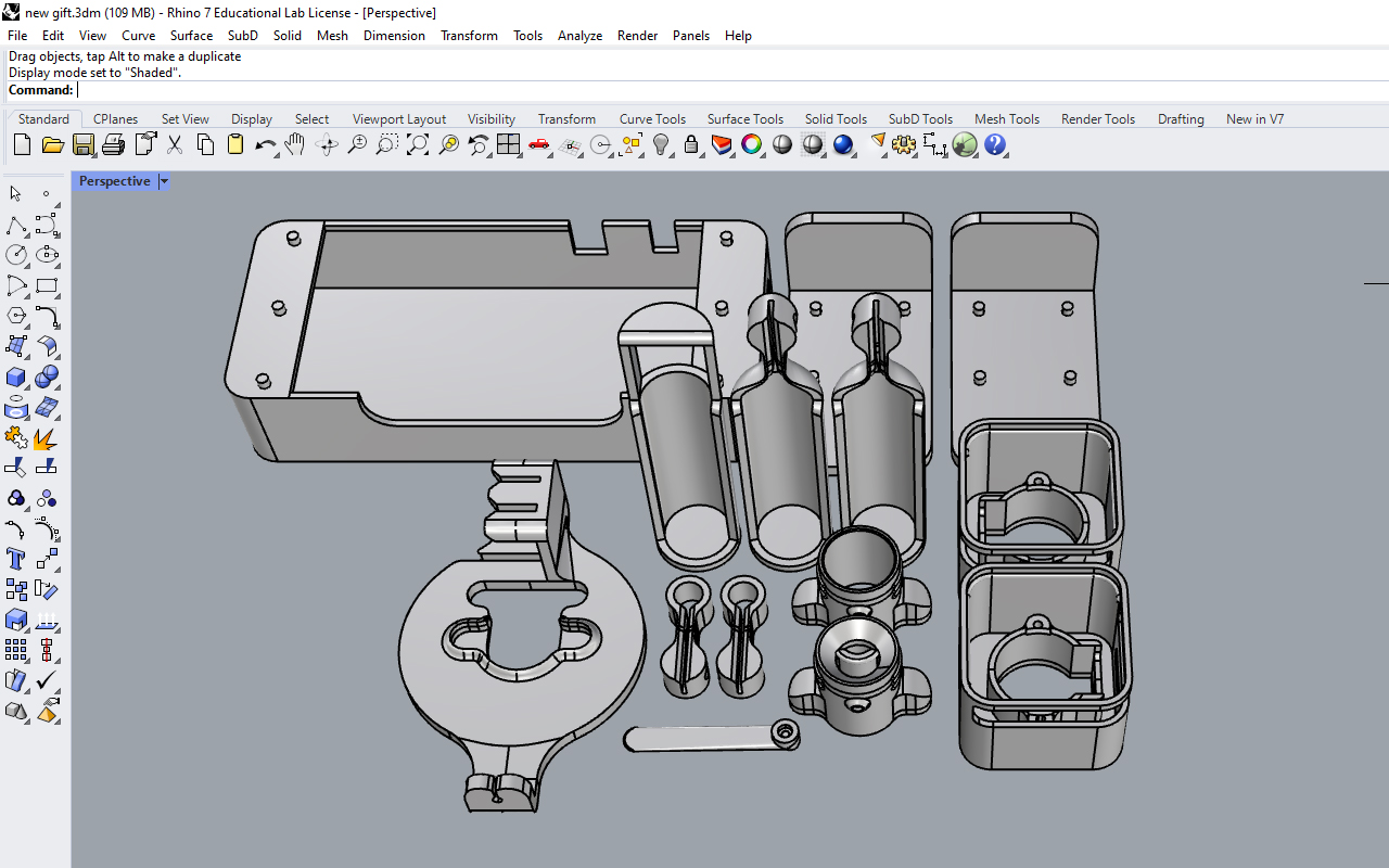

We realized that many current designs of the Gondola use screws to attach the belt cable connection. Willie felt that screwing can be a hassle so he changed the cable connection into a flexible press-fit design so that the fixture is faster and easier. What we needed to do was to press the cable connector part into the handle of the Gondola and that will do the job. If there is a need to remove them, we can just press the top and bottom portion of the handle and pull out the cable connector.
As for the stepper motor bracket, Willie did a casing for it as he did not like the exposed detail of the current design whereby the cable belts are hanging freely. Also, we realized that the cable belt tended to move off the grid when it was moving as there was no support around the belt to prevent the sudden drop in coordinates, so the casing design would also help to minimize the cable belt from moving off the grid.
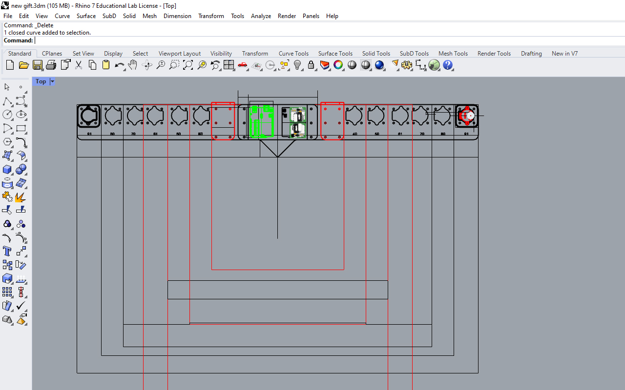
In the case that we need to do calibration of the cable belt, the casing comes with a clear acrylic screen whereby it can be taken off and put back easily by press-fitting. Below image show the design of having a modular frame system that can be adjust easily through press-fitting slots.
IThe design has contemplated some other parts for our XY plotter robot such as the 3 weights brackets (we are using ball-bearing as weights) for both stepper motors as well as the Gondola and last but not least, the Lifter part for the servo motor too.
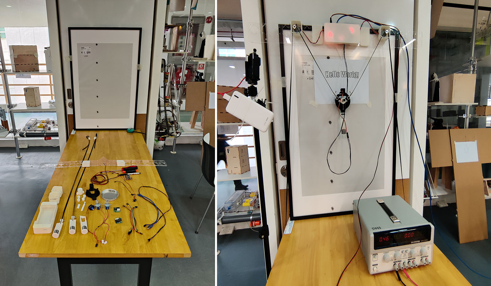
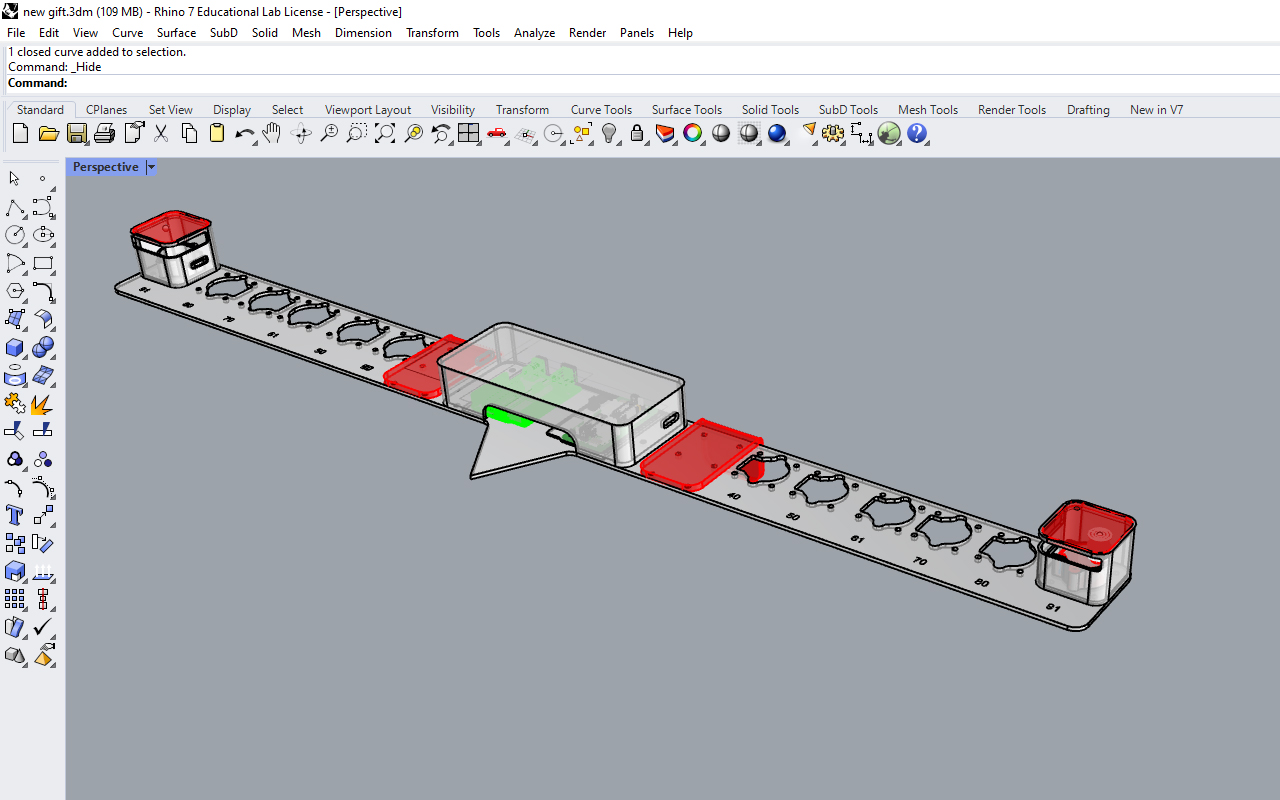
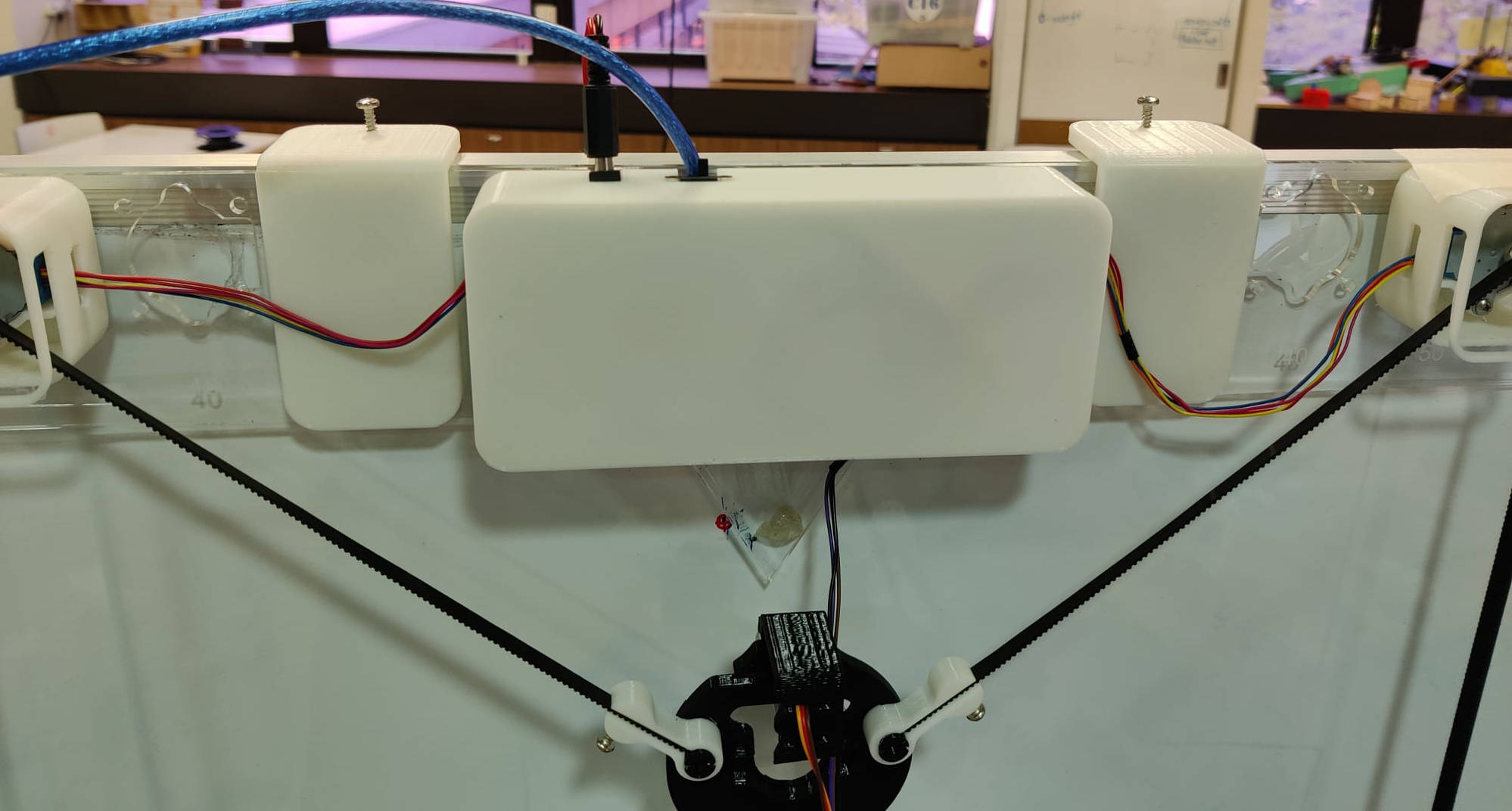
With that, our XY plotter robot is generally done. To make our XY plotter robot more versatile, our team has decided to add a frame design with modular hooks to it so that it can be mounted to any photo frames for drawing too.
The frame itself is made from laser cutting on acrylic with pre-designated slots so that the stepper motor bracket can be shifted according to the width of the photo frames. It also comes with a housing casing for our microcontroller and PCB so that everything is neatly contained.
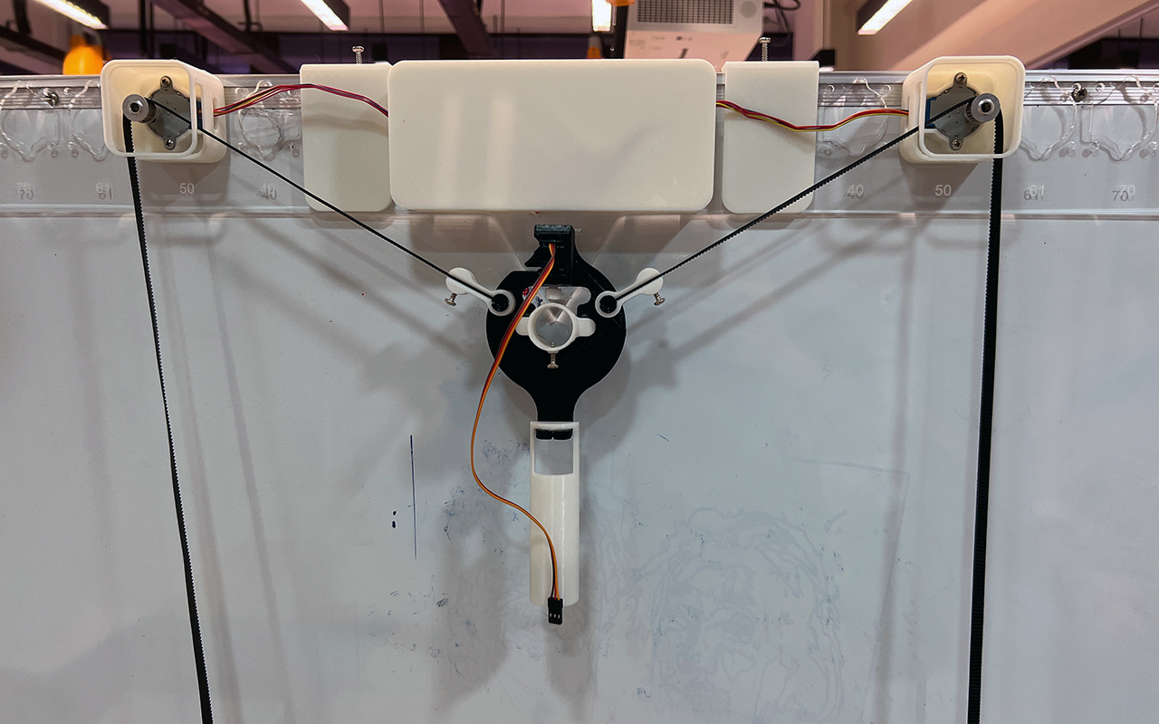
Lastly, the frame has an arrow point at a height of 120cm which is our calibration point (Home coordinate) for running the XY plotter so that users can calibrate with ease and there is no need to use rulers or measuring tape. Below is an image of how our XY plotter drawing robot would look like when mounted.
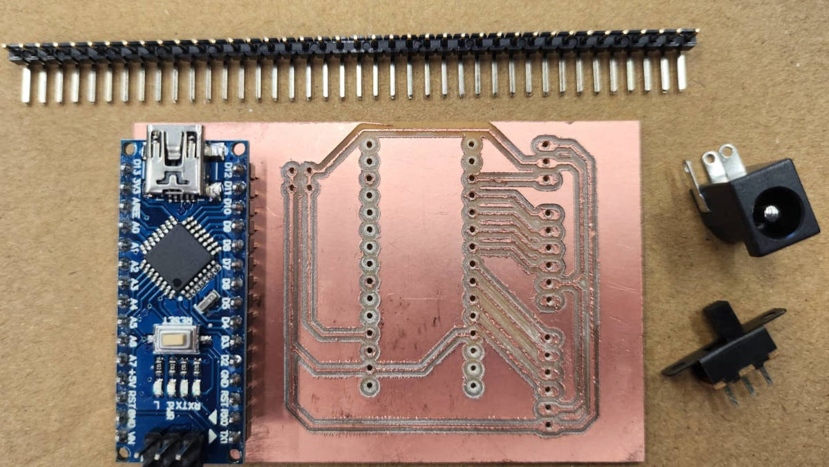
5.ELECTRONICS
After conducting the machine test, we found ourselves grappling with an excessive number of cables and connections. In order to simplify the process, we devised a solution to create our own PCB board, allowing us to eliminate the need for the Bread Board.
The newly-designed PCB board also features a 5V power input that accommodates an adaptor plug. It seamlessly connects to both the motor drivers and the servo motor through soldered pins.
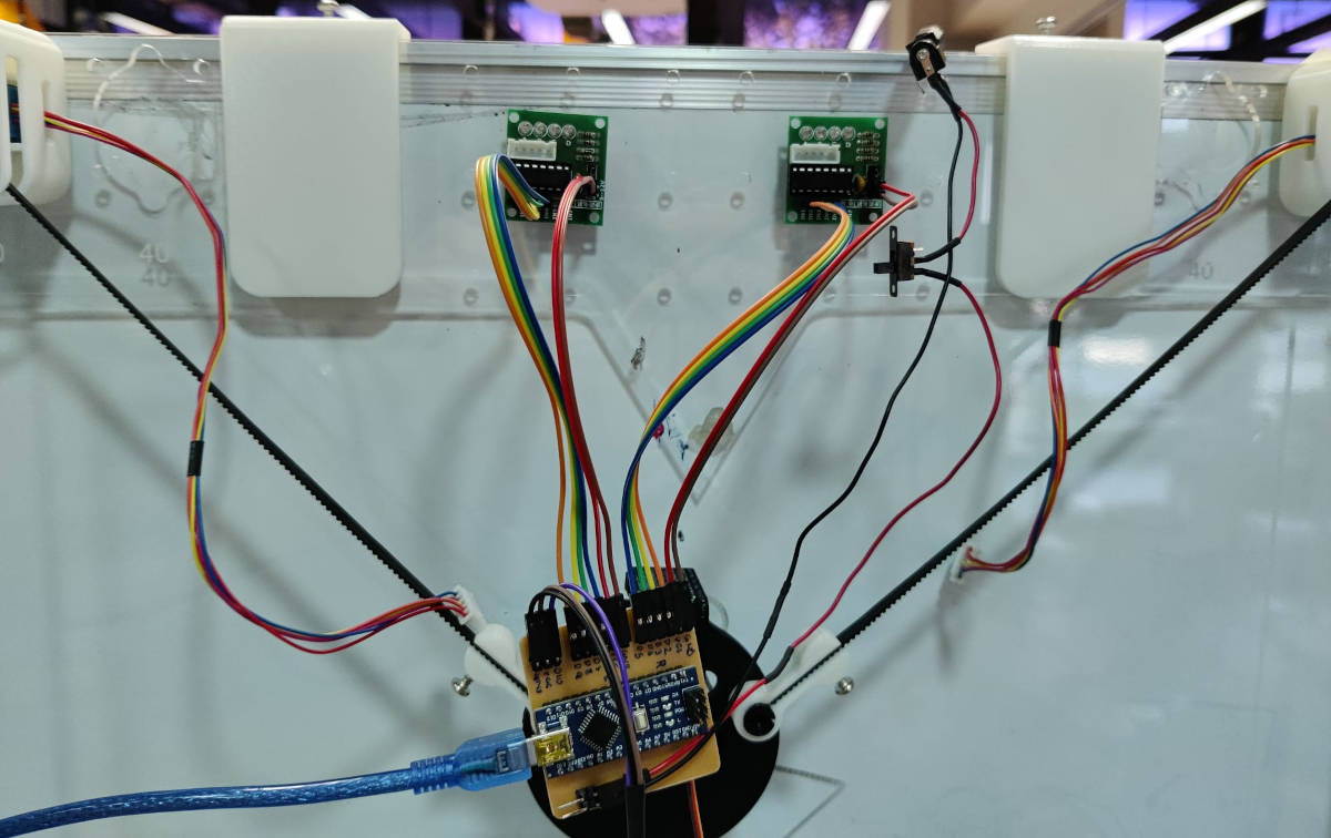
"The PCB board has been equipped with a custom-designed casing that effectively conceals both the cables and microcontrollers."
We encountered several issues during the PCB production process. Initially, the milling process was not completed accurately, causing incomplete pathways. Additionally, we neglected to check the microcontroller before soldering it to the board, leading to the discovery of a defect and ultimately resulting in damage to the board when attempting to remove it.
The pathway widths were also too thin, exacerbating the challenges we faced. Furthermore, the design called for the microcontroller to be placed on the top, which made it exceedingly challenging to perform the soldering process
|
|
Solutions:
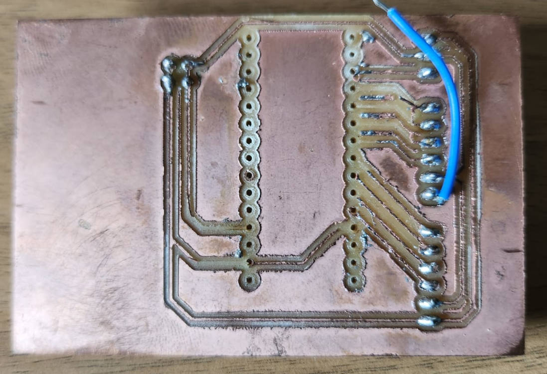
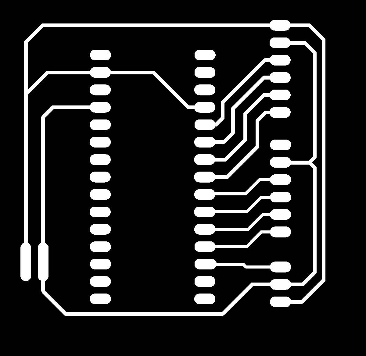
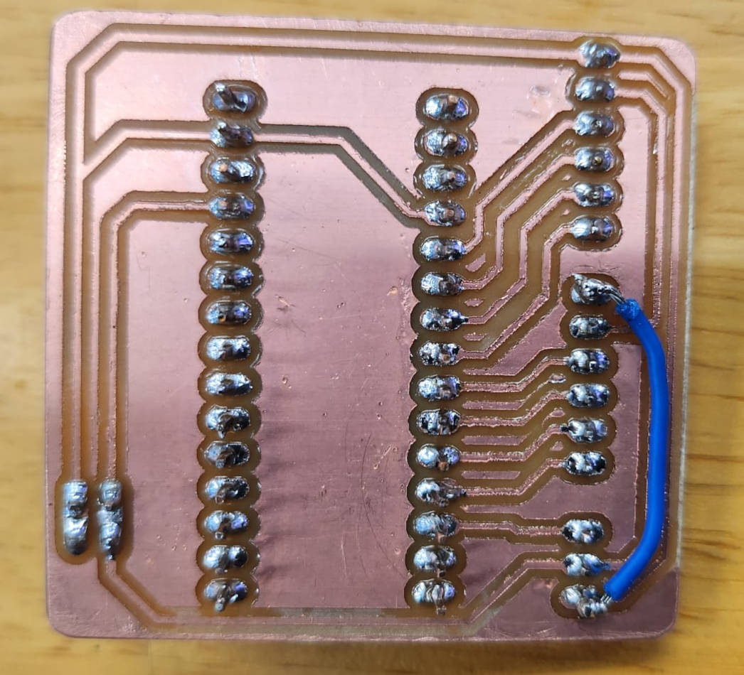
- Designing the paths to be printed in the "back of the Board" so we could solder the parts in the back of the PCB, we could never solved the way to connect with a path the Ground of the Stepper motor in the middle, so later we connect it with a jumper. We made sure that the paths for the power and Ground were thicker as they will be conducting 5V.
- In the previous milling we used a V-Bit of 0.01mm 20 degrees, we changed to 30 degrees so the lines were a bit thicker, and made sure the bed surface was even.
- Of cousre this time we tested that the microcontroller was connecting with the computer and uploading the Arduino Sketches.
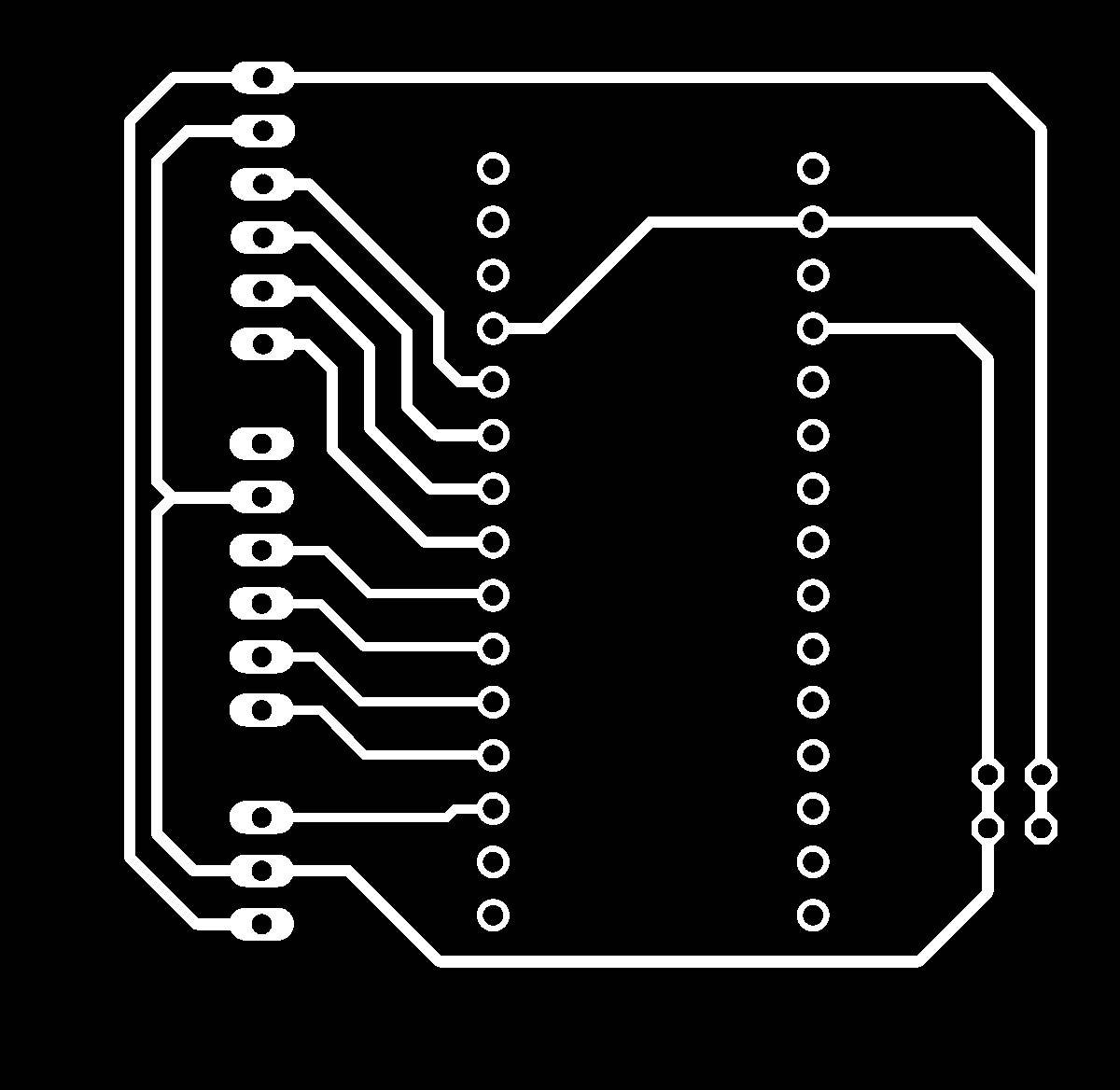
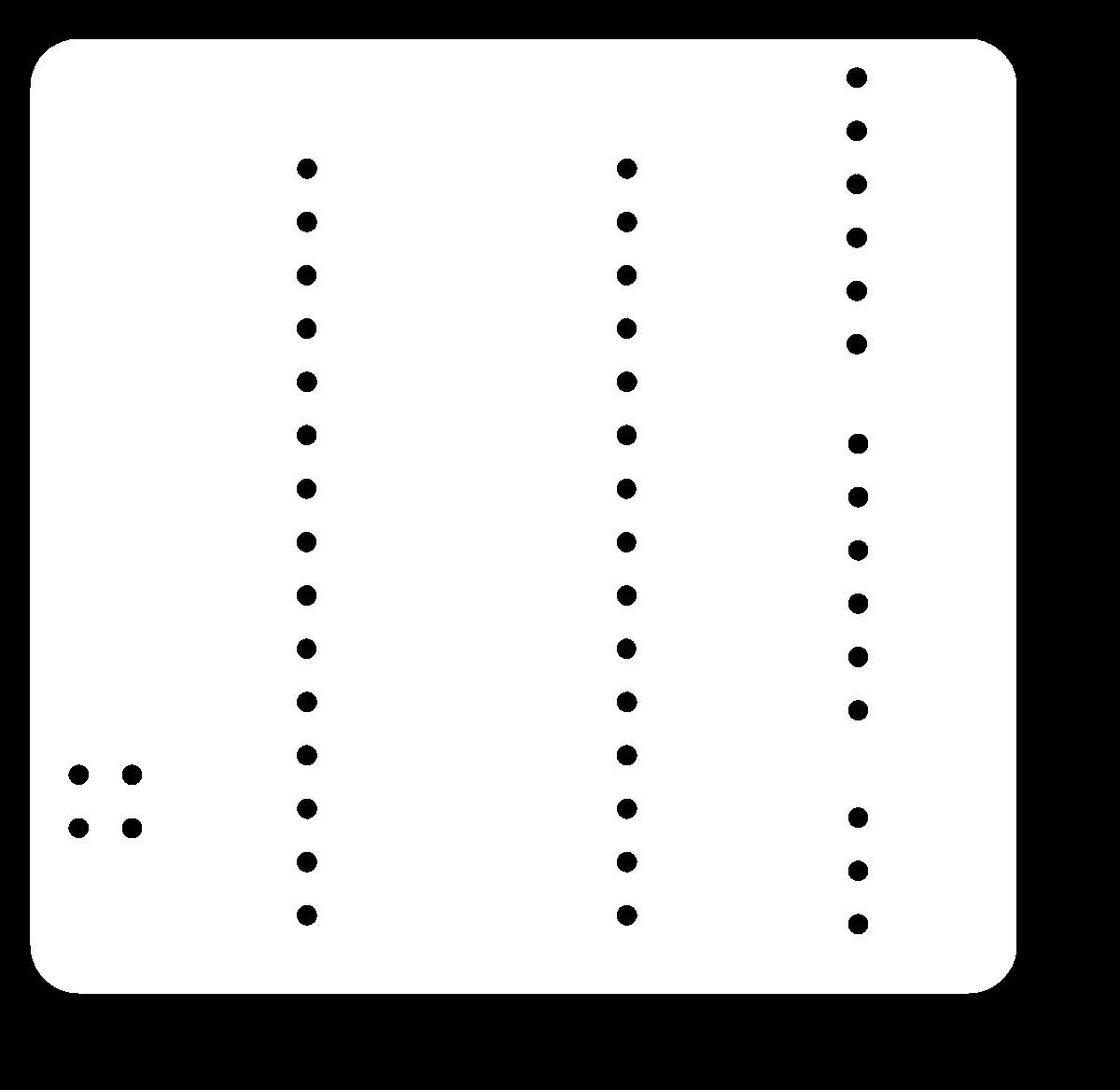
- And we solder the parts of the board at the back of the board, for this we had to mirror the PNG Images of the paths and the Outline generated from Eagle
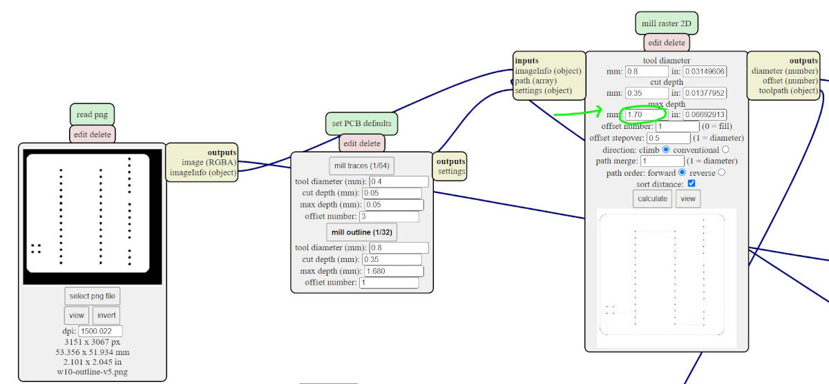
- And lastly, as the milling wasn't going through for the cutting of the outlines, we changed the settings to 1.70mm for the bit to go dipper, before it was 1.68mm.
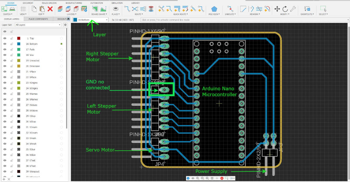
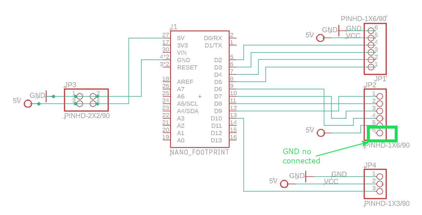
When running the ERC and DRC commands in Eagle the program told us we have a Ground in the system not connected, so we erased the connection to make it later with the jumper.
|
|
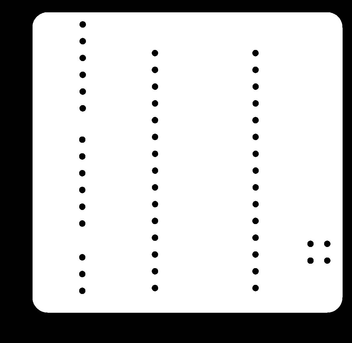
For the paths file, we did some corrections with GIMP, erase the drill holes, and made the paths for the microcontroller bigger, in the previous milling we ere left with very little copper and it was difficult to solder the pins of the microcontroller into the paths
|
|
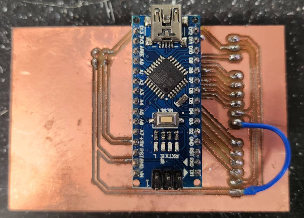
This is the final board!
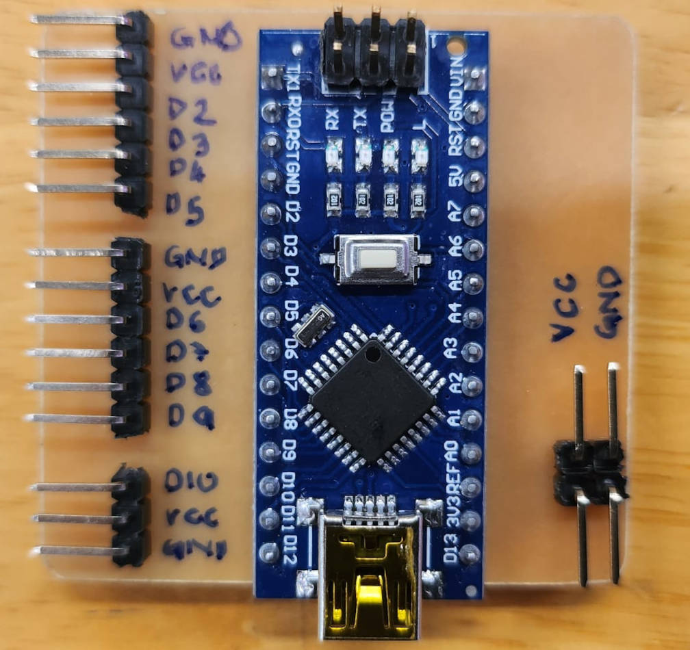
|
|