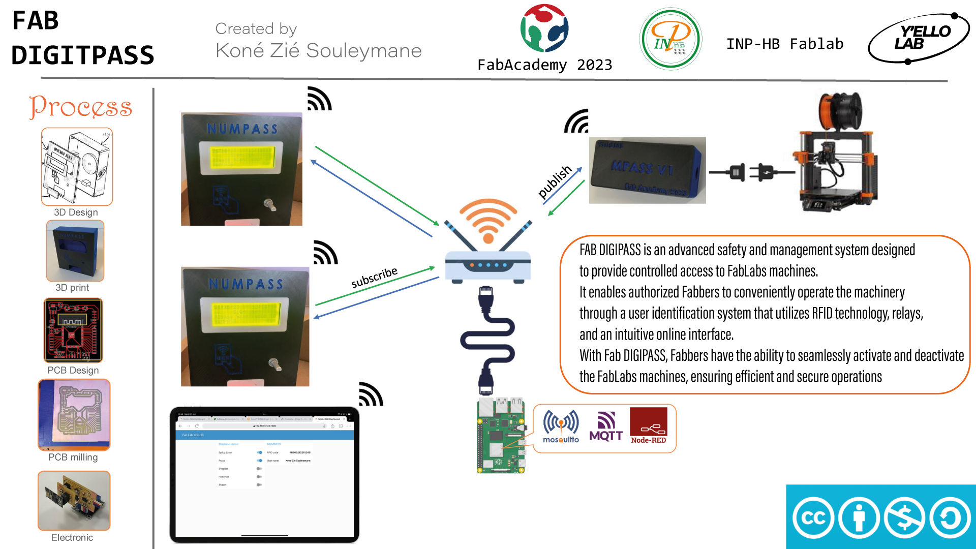
Project Development
This part will be about the process of making our final project. We will start from the sketch of the final project, passing by the design of the boxes, the electronic production to finish on the final presentation of the project.
I hope you will like my project.🤗
01. Sketch
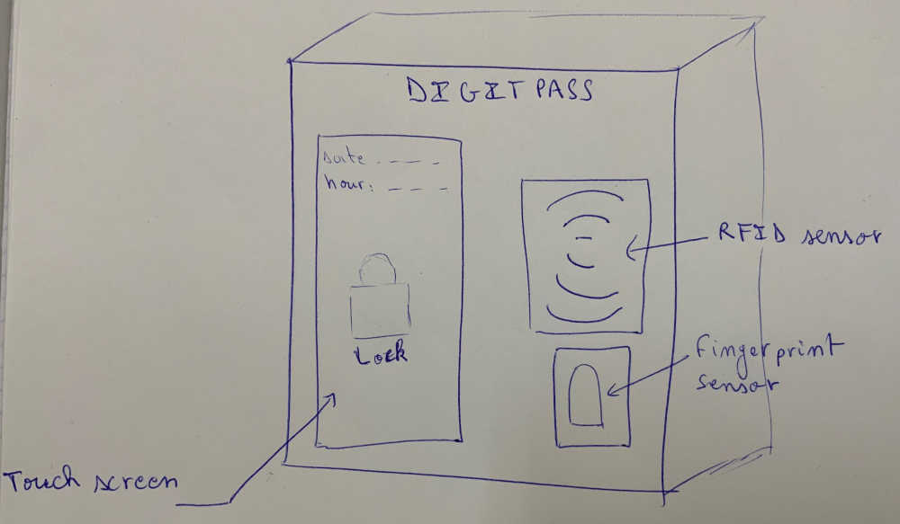
For my final project, I decided to design an access control system for the machines of a fablab.
The idea for this project came from the difficulties we have to manage and follow the access and maintenance of the different machines of our fablab.
The goal of this project is to design a device that will allow access to the machines only to qualified people, which will reduce the accident rate on the machines and increase their life span.
The device we will build will recognize people through an RFID badge.
02. Design of the MPASS and NUMPASS module housings
For the design we used the SolidWorks software.
NUMPASS
The design of the NUMPASS module case is made up of 4 parts, namely: the shell; the closure; the cover of the edge of the LCD screen and the cover of the signal LEDs as shown below.
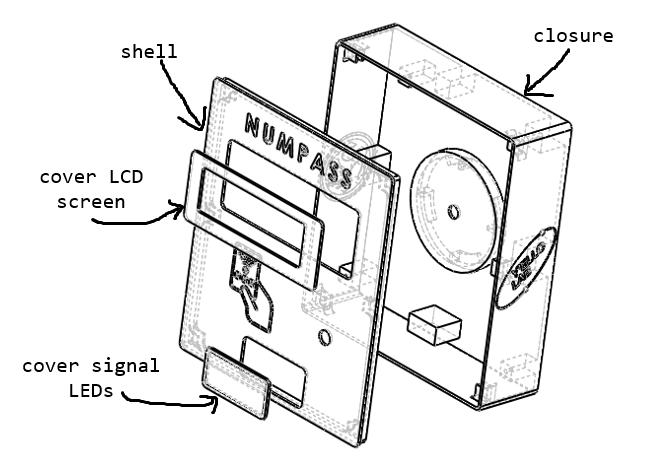
The files: NUMPASS Box SolidWorks file, NUMPASS Box STL file.
MPASS
we’ve designed two versions of the MPASS module, one for 3D printing, the other for laser cutting.
- MPASS V1
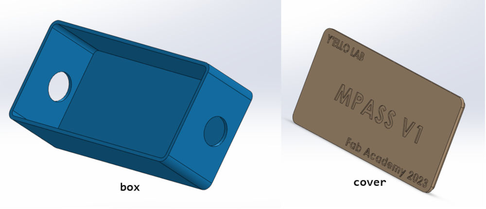
The files: MPASS V1 Box SolidWorks file, MPASS V1 Box STL file.
- MPASS V2
The files: MPASS V2 Box DXF file.
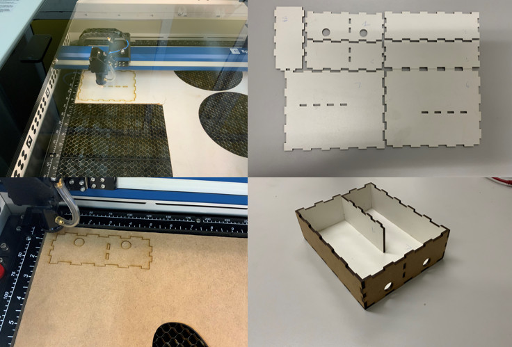
03. Laser cutting the MPASS V2 module housing
For the laser cutting of the MPASS V2 module housing we used an Epilog Edge 36 with 3mm MDF.
For more details on the cutting procedure refer to Week 3 Computer controlled cutting.
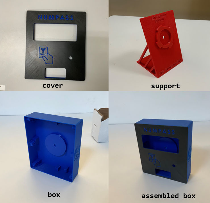
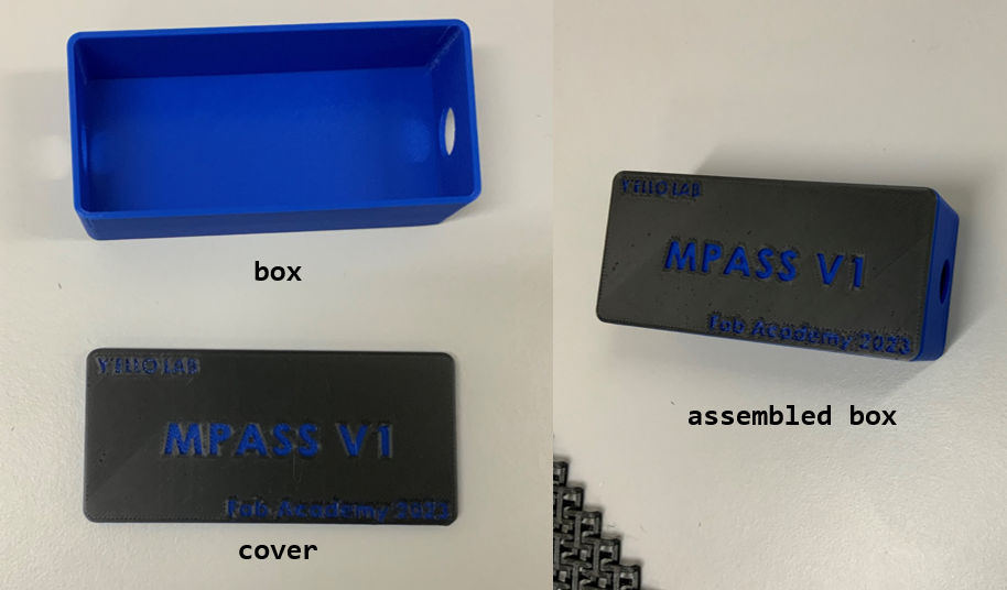
04. 3D printing of the NUMPASS and MPASS V1 module housings
for 3D printing we used the Prusa i3 MK3S+.
We used the same printing parameters for all our pieces, namely :
- Print setting: 0.20mm QUALITY
- Filament: Prusa PLA
Regarding the printing supports we have only used them on the shell of the cases.
For more fun we used PLA of various colors and the result is pretty cool.
For more details on the procedure and launch of 3D printing, please refer to Week 5 3D Scanning and printing.
- NUMPASS
- MPASS V1
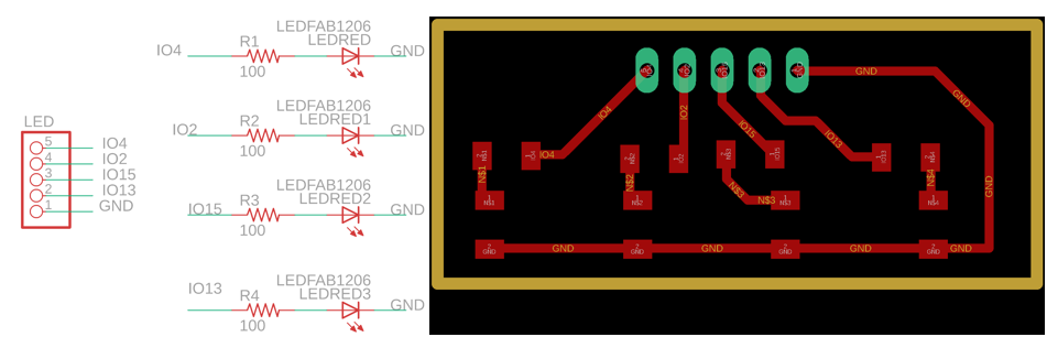
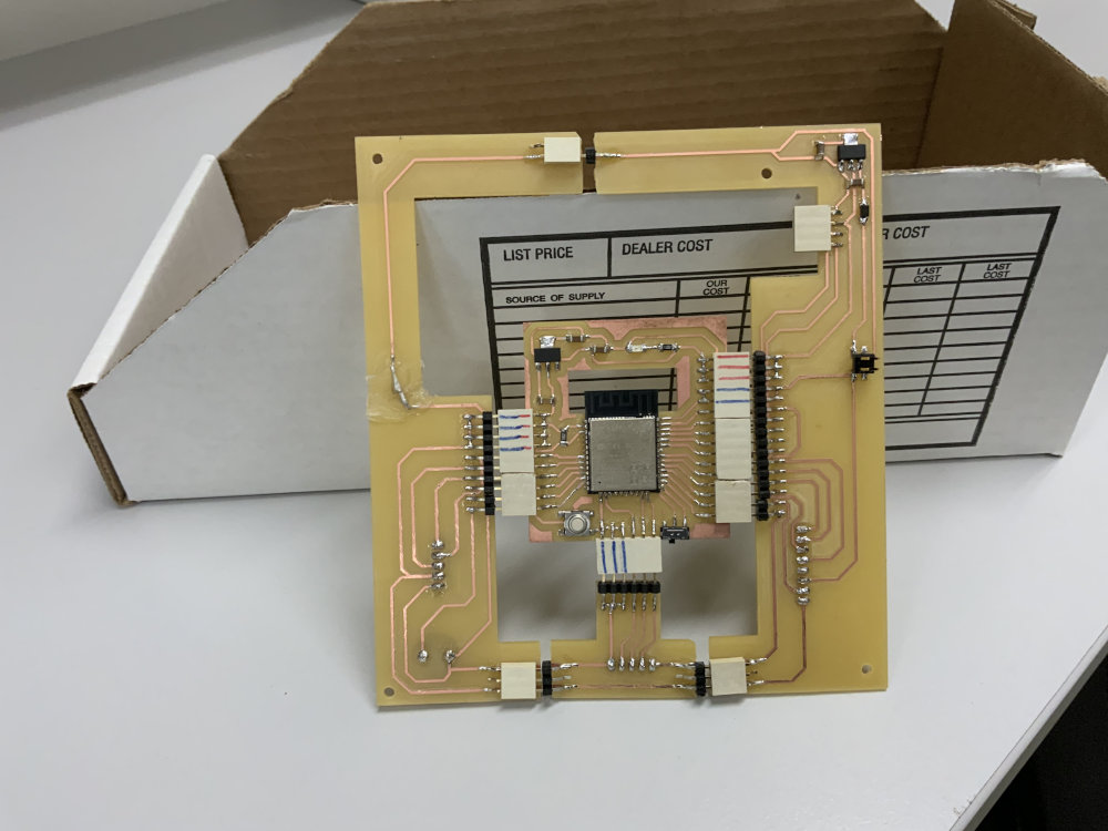
05. Electronic design of NUMPASS and MPASS modules
For the electronic design of our modules we used two softwares: kicad and eagle. For more details please refer to Week 6 (Electronics design).
Here’s a picture of our various electronic circuits.
NUMPASS
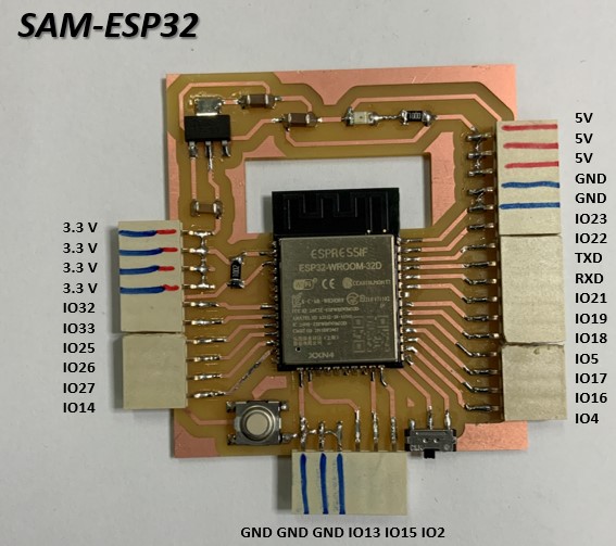
- SAM-ESP32 (MCU circuit board)
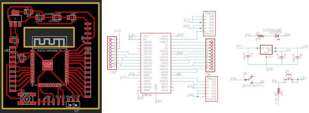
- NUMPASS circuit board
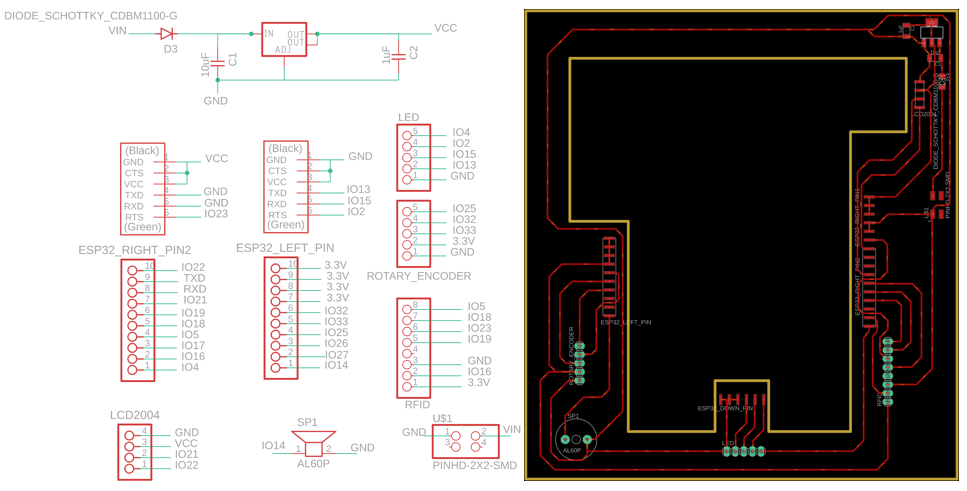
- LED circuit board
The files: NUMPASS circuit board file.
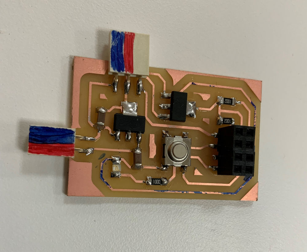
MPASS
- MPASS circuit board
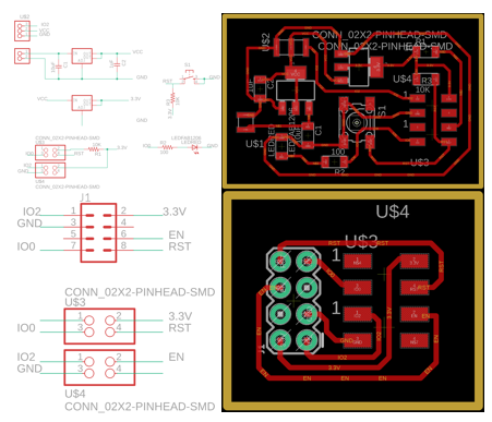
The files: MPASS circuit board file.
06. Electronics production of NUMPASS and MPASS modules
For the electronic production of our modules, we used the roland SRM-20 milling machine. For more details, please refer to Week 8 (Electronics production).
Here are photos of our various electronic circuit boards.
NUMPASS
- SAM-ESP32 (MCU circuit board)
- NUMPASS circuit board
MPASS
07. Programming and testing of NUMPASS and MPASS module inputs and outputs
For our final project we used the following components:
To program and test these different components, click on their names to be directed to the different weeks in which I’ve talked about them.
08. Programming and network configuration of the modules
For programming and configuration of the module network, please refer to Week 13(Networking and communications).
09. Interface programming
For interface programming, please refer to Week 14(Interface and application programming).
here’s a video demo of the results.
10 . Module assembly and testing
Before starting to assemble and test our various modules, we first programmed the different MCUs of our modules. You’ll find below our different programs made with Arduino IDE.
Note that we used the AsyncElegantOTA.h library to program our modules remotely over the Wifi network. For more details on the solution we used, click here.